 |
 |
- Search
| J. Ocean Eng. Technol. > Volume 35(3); 2021 > Article |
|
Abstract
Tomographic particle image velocimetry (PIV) is a widely used method that measures a three-dimensional (3D) flow field by reconstructing camera images into voxel images. In 3D measurements, the setting and calibration of the camera’s mapping function significantly impact the obtained results. In this study, a camera self-calibration technique is applied to tomographic PIV to reduce the occurrence of errors arising from such functions. The measured 3D particles are superimposed on the image to create a disparity map. Camera self-calibration is performed by reflecting the error of the disparity map to the center value of the particles. Vortex ring synthetic images are generated and the developed algorithm is applied. The optimal result is obtained by applying self-calibration once when the center error is less than 1 pixel and by applying self-calibration 2–3 times when it was more than 1 pixel; the maximum recovery ratio is 96%. Further self-correlation did not improve the results. The algorithm is evaluated by performing an actual rotational flow experiment, and the optimal result was obtained when self-calibration was applied once, as shown in the virtual image result. Therefore, the developed algorithm is expected to be utilized for the performance improvement of 3D flow measurements.
Particle image velocimetry (PIV) is a contactless and quantitative flow measurement method that is widely used for internal and external flow measurements in various fields, such as fluid machinery, ocean engineering, and environment-friendly energy generation. In particular, PIV is an effective visualization method for experimental approaches in complex marine areas such as the flow field measurement of submerged bodies in the ocean (Hong et al., 2019) and flow structure analysis of breaking waves (Jo et al., 2009). In this method, tracer particles are placed in the fluid flow and the behavior of the particles is examined using cameras by particle tracing, thereby finding a vector or vector field. This method has evolved from two-dimensional (2D) PIV and 2D particle tracking velocimetry (PTV) that involve finding a three-dimensional (3D) vector or vector field through the use of an observation equation in the images obtained from two or more cameras. Various methods have been studied and developed, including stereoscopic PIV (SPIV), holographic PIV (HPIV), tomographic PIV (TomoPIV), and tomographic PTV (TomoPTV) (Arroyo and Greated, 1991; Doh et al., 2012a; Elsinga et al., 2006; Hinsch, 2002).
Among them, TomoPIV is a 3D flow-measurement method that reconstructs 2D pixel images that are obtained using several cameras as a 3D voxel image and utilizes the 3D cross-correlation in the reconstructed voxel image to measure the velocity field (Doh et al., 2012b; Elsinga et al., 2006). The novelty of TomoPIV is the reconstruction of a 3D image from multiple 2D images obtained from different perspectives. Among the many 3D reconstruction methods, algebraic reconstruction techniques (ART), multiple ART (MART), simultaneous ART (SART), and simultaneous multiplicative ART (SMART) are widely used (Andersen and Kak, 1984; Byrne, 1993; Herman and Lent, 1976). These methods have both advantages and disadvantages depending on the calculation time, accuracy, and flow field characteristics.
In 3D measurements using PIV, the observation equation setting of cameras and the camera calibration significantly impact the results. Thus, many studies have been conducted to improve the observation equations and calibration methods (Prasad, 2000; Soloff et al., 1997). However, there are camera calibration errors depending on the hardware and algorithm. To reduce the occurrence of such errors, a volume self-calibration (VSC) method has been developed (Wieneke, 2008). The VSC method first determines the 2D particle positions in the 2D camera images, followed by the positions of all particles that can exist in the 3D space. The difference between the positions of particles at the time when the particles in the 3D space were projected to each camera and the positions of the particles in the image is the calibration error of the camera. The error is minimized by a method that reflects the error in the position values of the particles and performs the calibration again. The VSC method has been continuously improved by many researchers (Wieneke, 2008; Lynch and Scarano, 2014).
Among them, Doh et al. (2012a) used an equation derived from pinhole model’s observation by exploiting 10 intuitive parameters to develop TomoPIV and VolumePTV algorithms, and they compared the advantages and disadvantages of each algorithm. In this study, we perform self-calibration by using the VSC method through the observation equation with 10 parameters proposed by Doh et al. (2012a). We also develop a VSC algorithm that improves the performance of the TomoPIV and TomoPTV algorithms.
The observation equation of cameras is an equation that shows the relationship between the camera coordinates and the spatial coordinate system; it is expressed as follows:
In Eq. (1)Mi is an observation equation for the image coordinates (xi,yi) and the spatial coordinates (X, Y, Z) for the i-th camera. For every camera, the corresponding observation equation is used to convert the spatial coordinates to the image coordinates. Conversely, a point on the image is represented in a 3D space by using the inverse transform of Eq. (2):
In other words, a point on the image is represented by a line-of-sight (LOS) function, for which it is expressed in the form of a straight line according to the position of Z in the space. Therefore, a point on the image has a solution corresponding to a straight line in the space, and it is represented as a line in each camera. Finally, the position that minimizes the LOS error of the matching particles of each camera is determined as a 3D position. Various methods of camera observation equations have shown the relation between the space and the camera image; however, in this study, we used an observation equation that had 10 elements [camera’s external elements (d, α, β, κ, mx, my ) and internal elements (cx, cy, k1, k2 )] used by Doh et al. (2012a), which were intuitively represented by using the camera distances and rotation angles. It is expressed as follows:
cx and cy denote the ratio between the image and space for the x- and y-axes, respectively, and d denotes the shortest distance between the center of the camera and the plane that passes through the zero-point of the space. Xm, Ym, and Zm are the spatial coordinates rotated by α, β, and κ on the X-, Y-, and Z-axes, respectively, in the space. mx and my denote the misalignment between the z-axis in the image space and the Z-axis in the 3D space, and ∆x and ∆y are the equations that represent the degree of refraction of the lens, which are expressed as follows:
The camera calibration uses a 3D position point P (X,Y,Z) in the space and a position point p(x,y) on the image to determine the element values of the observation equation that minimize the error of Eqs. (3)–(5). It uses special marks such as circles or cross marks on the calibration plate to provide the X and Y information; by providing the Z information while vertically moving at certain intervals on the calibration plate, the 3D position information P (X,Y,Z) is obtained. Here, the cameras are used to obtain the image of the calibration plate, and image processing is used to obtain the position of the marked points, p(x,y). Using the position information that is obtained in this way, the element values of the observation equation are determined in such a way that the RMS (root-mean-square) error of the position points is minimized; based on this, the camera is calibrated. The obtained camera calibration values have many errors arising from the error of the mark points on the calibration plate, the error of Z-axis movement on the calibration plate, the error of image acquisition device, algorithm errors occurring during the process of finding the center and finding the optimal solution, and others. These errors have adverse effects on the reconstruction of voxel images. Moreover, the reliability of the 3D measurement result can be considerably improved by minimizing these errors.
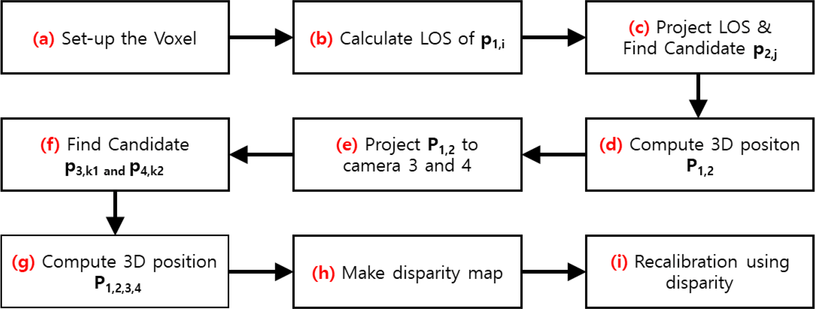
To this end, this study developed a self-calibration method that minimizes the errors of the cameras using the process shown in Fig. 1.
The centers of particles are obtained in every camera image. The process for self-calibration includes the following steps: (a) The region and shape of a virtual 3D voxel space are determined from the entire region to be measured. Here, for the size of the voxel image, the ratio of the pixel and the voxel is maximally set to 1 to reduce the errors in the calculation (Scarano, 2013). (b) The inverse transform of the observation equation for the i-th particle, p1,i in the image of camera 1 is utilized to obtain the LOS. (c) The obtained LOS is projected to camera 2, and all particles, p2,j, within a certain distance (1.5 voxels is used in this study) from the LOS are obtained. (d) Particles p1,i and p2,j that are selected in the two cameras are used to find the 3D position, P1,2. In other words, P1,2 is the position in the 3D space where two straight lines meet, i.e., the LOS of p1,i and the LOS of p2,j. (e) When the LOS for a single particle is projected to the other camera, the projected LOS is a straight line across the image in the other camera. Therefore, multiple particles exist on the straight line, and from this, results are obtained, including not only the actual particles but also many virtual particles. To reduce the number of such virtual particles, the obtained 3D particle, P1,2, is projected onto the images of the remaining cameras 3 and 4. (f) If a particle exists within a certain distance (1.5 voxels) from the position of the particle projected onto the camera (p3,k1 and p4,k2), then it is determined to be a real particle; otherwise, it is determined to be a virtual particle. (g) For only the particles that are determined to be real particles, the new 3D particle’s position is calculated using the least square method from the selected 2D particle positions (p1,i, p2,j, p3,k1 and p4,k2) corresponding to each camera. (h) This process is used to find all possible 3D particles for every particle of camera 1, and the particles corresponding to the coincident regions that are set up based on the voxel position are classified and collected. (h) The 3D particles that are collected for each region are used to compose a disparity map.
The disparity map refers to an image that shows the difference between a particle position on the camera image and a particle position that is obtained by projecting onto the image of the camera the 3D particle that was calculated using that particle. To obtain the disparity map, all 3D particles of the corresponding region are first projected onto each camera image in order to obtain the coordinates. The error between the projected coordinates and the particle’s center on the image is obtained, and the particles of the Gaussian distribution with a sigma of 1 voxel are drawn at the position distanced by the error from the center and superimposed on the disparity map. In this study, the pixel size was magnified by a factor of 10 to improve the accuracy. For a high degree of accuracy, it is necessary to superimpose many particles deemed as real particles. Therefore, in this study, we calculated the 3D positions from thousands of test images until more than 10,000 particles are superimposed in each voxel region, and we superimposed them on the disparity map to draw the Gaussian particles, thereby composing the entire disparity map.
If the peak point is obtained in the disparity map for all regions, then the distance between the peak point and the center is the calibration error. As the last step, the obtained fixed error is reflected in the center value of the particle to perform the recalibration, and the parameters of the camera observation equation are then changed to perform the self-calibration.
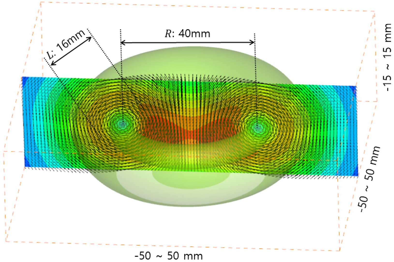
To evaluate the performance of the self-calibration method developed in this study, we set the measurement region to be −50 mm to 50 mm, −50 mm to 50 mm, and −15 mm to 15 mm on the X, Y, and Z axes, respectively. The camera image size was set to 512 × 512 pixels, and the cameras were placed in a row by setting the rotation angle of the X-axis to −20°, −5°, 5°, and 20°. The voxel size was 500 × 500 × 150 voxels, and 1 mm corresponds to 5 voxels. To produce a virtual image, we used a ring vortex flow field that is expressed by the following equation for the flow of particles:
where d is the vector size, u,v, and w are the vector components. l represents the thickness of the ring vortex, r1 and r2 denote the distance from the center of the ring vortex. Fig. 2 shows the virtual ring vortex flow field that is applied in this study, and its thickness and size are 16 mm and 40 mm, respectively.
In this study, after performing the initial calibration using a virtual calibration plate, a particle with a diameter of 2.5 voxels was created in the voxel space, and then thousands of virtual particles [particle per pixel (PPP) = 0.01] were created. Based on the created voxel image, a virtual image was produced again using the following equation:
where superscript i denotes a pixel in the camera image, j denotes a voxel in the 3D space, I is the virtual image, and V is the voxel image. wij denotes the weight according to the distance between the camera pixel’s LOS and voxel. In other words, the brightness of the virtual image is determined by the sum of values obtained by multiplying the weight by all voxels existing in a certain range of the LOS. In this study, the above method was used to produce voxel images and the virtual image for each camera.
As explained in Section 2.2, the voxel space was subdivided into 5 × 5 × 5 regions for the self-calibration, and the process of Section 2.2 was performed repeatedly for each region, thereby producing a disparity map, as shown in Fig. 3.
Fig. 3 shows disparity maps of 125 points according to 25 points on the XY plane, and 5 points of z-axis for camera 1. First, in the disparity map that is based on the initial calibration values without self-calibration, the misaligned center has a large error, but the regions are widely distributed. As the self-calibration is performed, the shapes of particles in the disparity map converged at the center point and improved.
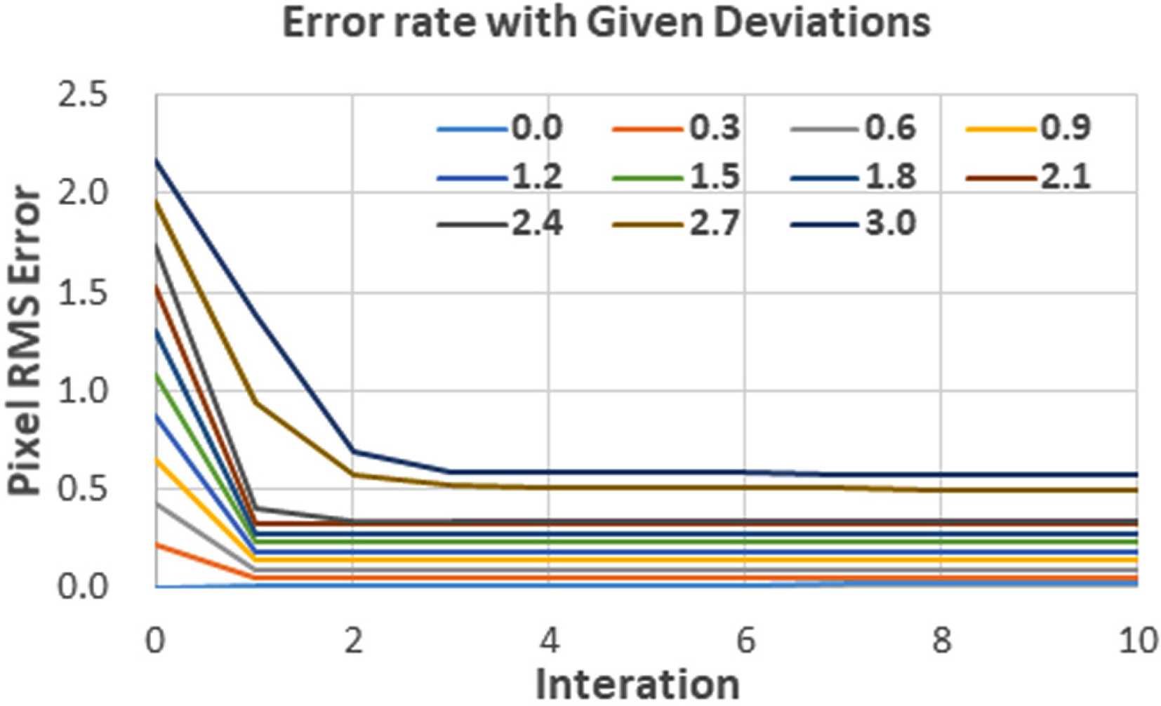
The error in the algorithm was evaluated by assigning a random error to the center of the particle in order to evaluate the degree of convergence of the self-calibration, and the results are shown in Fig. 4.
As shown in Fig. 4, the errors are high initially because of the given random errors, but as the first self-calibration is performed, most of the errors were improved. When the center error was 1 pixel or higher, the optimal result could be obtained by repeating the self-calibration two or three times, and even if the self-calibration was repeated, there was no further improvement above a certain level. This result shows that the developed self-calibration algorithm significantly improves the errors that can occur during the camera calibration process. Furthermore, it was found that it is not necessary to repeat the self-calibration more than two or three times depending on the error size.
Next, a multiplicative algebraic reconstruction technique (MART) algorithm was used to reconstruct the voxel image (Atkinson and Soria, 2009; Elsinga et al., 2006; Worth et al., 2010; Doh et al., 2012b). The MART algorithm is a reconstruction algorithm that is widely used in the field of tomography. This method combines the 3D image intensity along the LOS to obtain the projected 2D image and reconstructs a 3D image by making a comparison with the original image. This process is repeated to reconstruct the entire 3D voxel image, and the algorithm is represented by the following equation:
where μ is the coefficient of convergence, and ω is the coefficient of weight according to the distance between the LOS for the i coordinate of the image selected as the weight and the voxel j. In other words, this algorithm reconstructs the voxel image in such a way that the ratio of the sum of all voxel images existing on the LOS to the brightness of the image at the pixel position on the image will converge to 1. The voxel image reconstructed by the MART method and the voxel image produced virtually were directly compared using the following equation to evaluate the accuracy of the proposed algorithm:
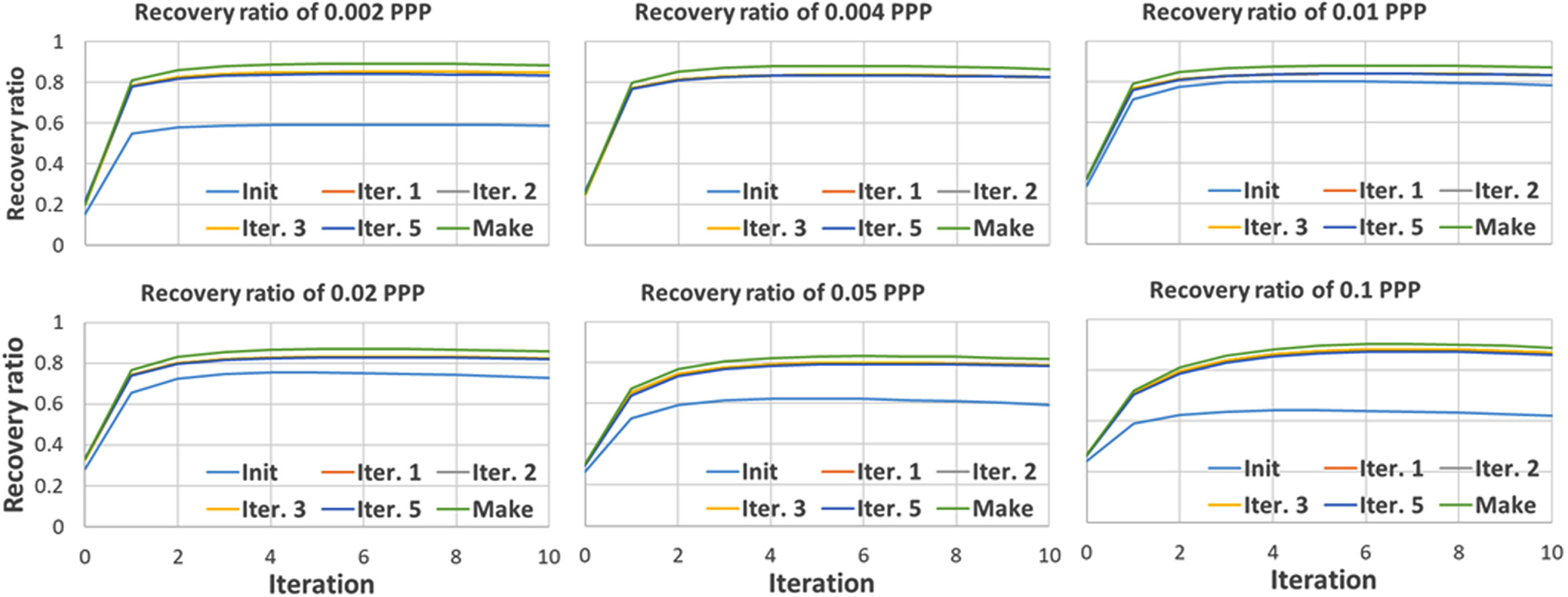
In Eq. (9)Q denotes the recovery ratio, which indicates the reconstruction accuracy, and the superscripts R and C represent the reconstructed and created voxel images, respectively. Fig. 5 shows the recovery ratio of the voxel image according to the PPP (number of particles per pixel). Here, the recovery ratio indicates the degree of recovery of the particles, which existed before the calculation, after performing the calculation based on the virtual image. The voxel images were created by setting PPP to 0.002–0.1. The performance of the constructed calculation algorithm was determined by evaluating the recovery ratio. Fig. 5 shows the reconstruction performance results that are expressed by Eq. (9) of the voxel image according to the result of the self-calibration for each PPP. When the recovery ratio is 1, it means that the reconstructed image and the created image match perfectly.
The “Make” indicator that is illustrated in each figure shows the result of reconstructing the voxel image by employing the variable values of the cameras used in the voxel image creation, and the “Init” indicator shows the result of reconstructing using the camera calibration values without the self-calibration. The “Iter. 1,” “Iter. 2,” “Iter. 3,” and “Iter. 5” indicators show the results of reconstructing the voxel image after performing the self-calibration process 1, 2, 3, and 5 times, respectively. Furthermore, the x-axis in the figure represents the number of iterations in the MART algorithm. The value 0 is the voxel value that is initialized using the MLOS (multiplied line-of-sight), and finally, the MART algorithm was repeated 10 times for the calculation.
As a result (Make) of performing the MART algorithm with the ground truth used in the virtual image creation, a recovery ratio close to 90% was obtained. However, it decreased as the PPP increased, showing the maximum recovery ratio of about 70% when the PPP was 0.1. The number of virtual particles increased significantly as the number of particles in the space increased, and the voxel ratio decreased significantly as the number of particles increased.
“Init.” indicates the recovery ratio when the calibration is performed using the calibration plate and the self-calibration is not performed. The best recovery ratio is shown when PPP is 0.004, but it decreases sharply as the number of particles increases. Based on the result of performing the self-calibration algorithm developed in this study, the recovery ratio was higher compared to the case when the self-calibration was not performed. A high improvement rate was observed in the first self-calibration, but even when the self-calibration was performed two, three, or five times, the result was similar to that of the first self-calibration. This implies that a good result can be obtained by performing self-calibration only once. Furthermore, when the MART algorithm was repeated five times with a PPP of 0.05, a recovery ratio of 74% was shown based on the recovery ratio of Make, but when the self-calibration was performed, a high recovery ratio of 96% was shown. Based on this result, it was determined that the developed self-calibration algorithm exhibits significant improvement.
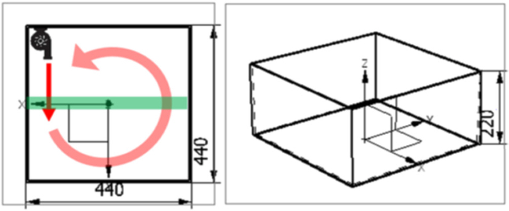
To evaluate the performance of the algorithm developed in this study, we created an experimental flow, as shown in Fig. 6. The size of the water tank was (440 × 440 × 220) mm3, and a pump having a flow rate of 540 L/h was installed to create a constantly rotating flow. Then, polyamide nylon particles with a diameter of 50 microns were inserted. An 8-W Laser System Europe Blits Pro Laser was used as the light source, and the laser light was projected with a thickness of about 10 × 10 mm, as indicated by the green region in Fig. 6. Four high-speed cameras were installed by arranging them in a row in such a way that the rotation angle will be approximately −15°, −5°, 5°, and 15° from the front side.
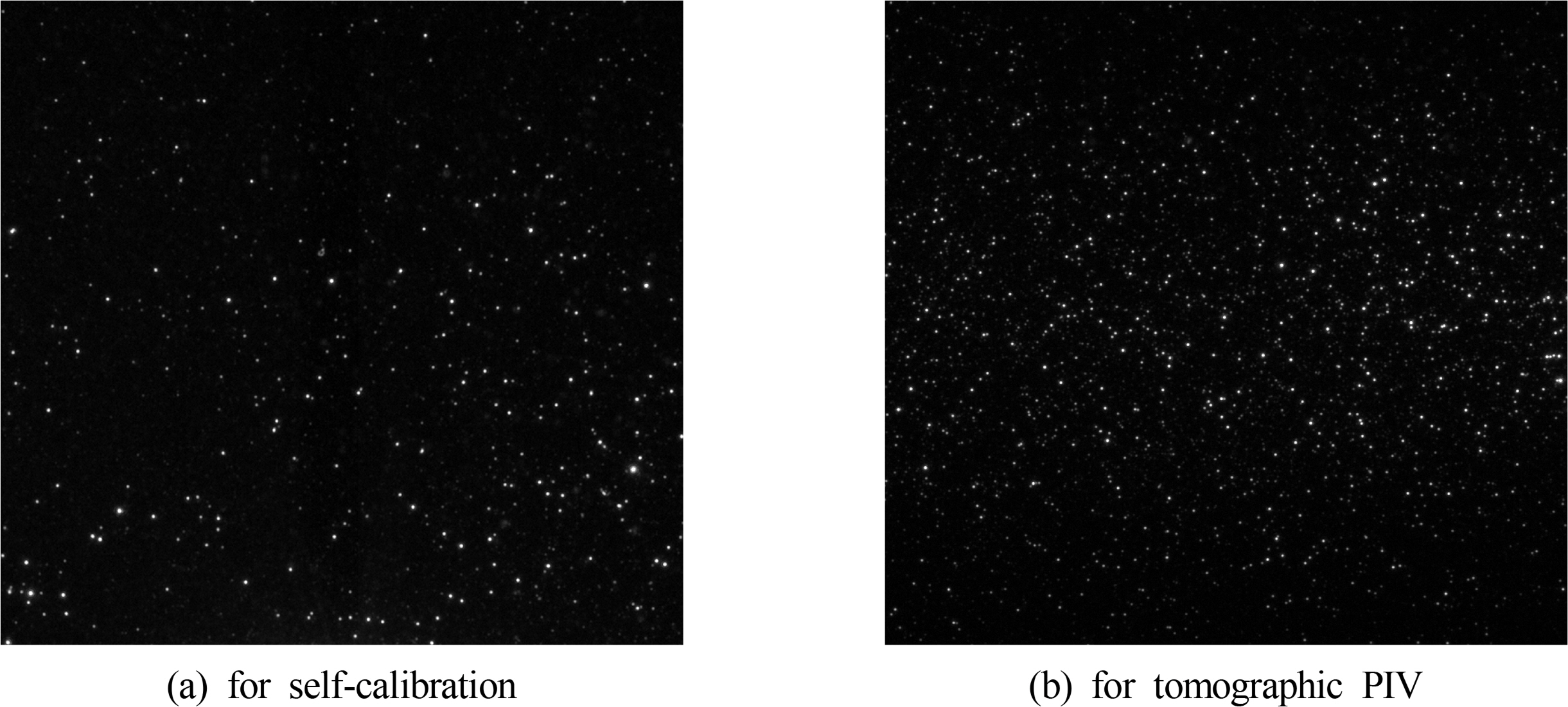
A flat calibration plate of a circular pattern was used to perform the calibration. Here, the total measurement area was (40 × 10 × 10) mm3. Fig. 7 shows an image of the first camera obtained in the experiment. To minimize the number of virtual particles, a small number of particles were entered to obtain a low-density particle image (1,000 particles, or about 0.001 PPP in an image of 1,216 × 1,200 resolution); then, after performing the self-calibration, a high-density particle image (about 10,000 particles or 0.01 PPP) was obtained for the tomographic PIV measurement, and the velocity vector was measured.
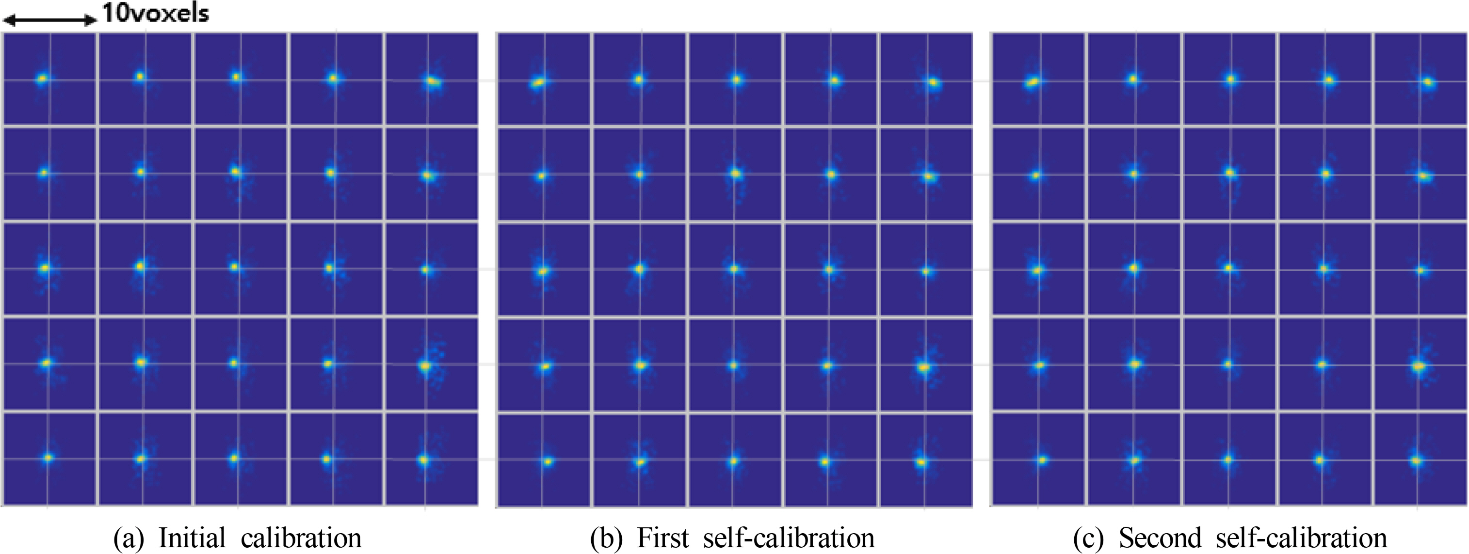
Fig. 8 shows the disparity map obtained when performing the self-calibration. As shown in Fig. 8(a), when the self-calibration was not performed, the center of the particle was misaligned sufficiently for it to be distinguished by the human eye. In the case of the center, most errors were less than 0.2 pixel, but in the case of the flank, some errors were larger than 0.5 pixel. When the self-calibration was performed, these errors decreased significantly, and after performing the first self-calibration, the pixel errors of all points had converged to less than 0.2 pixel. However, when the self-calibration was performed two or more times, the pixel errors did not change much. This implies that a sufficiently good improvement effect can be obtained by performing the self-calibration once or twice in the experiment.
To analyze the effect on the actual experimental results, we used a fast Fourier transform (FFT) cross-correlation in two recovered continuous voxel images to obtain the vector, and we evaluated the errors based on the method of using a medium filter expressed by the following equation:
In the equation, vm is the value located in the middle when a total of 27 vectors were arranged in 3 × 3 × 3 regions. vi is the current vector. When the rate of change of the vector was larger than median vm, it was determined to be an error. Fig. 9 shows the error rate of all vectors when the evaluation was performed with the median filter. When the camera’s self-calibration was not performed, ∼10% of all vectors were determined to be errors. After completing the self-calibration stage, the error rate decreased to 8.8%, and as the self-calibration was repeated, the result showed a slight improvement. However, after repeating it more than three times, there was no further improvement in the result. Instead, when the self-calibration was performed five times, the error rate increased by 0.002%, which was negligible. Based on these results, it is found that the optimal frequency of performing the self-calibration is three times in the case of the given experiment. Furthermore, the optimal frequency of self-calibration can be determined through the error rate analysis using the median filter.
This study discusses the measurement performance improvement of the TomoPIV method, which is a 3D velocity field measurement method of a flow field using an observation equation of a ten-parameter-based pinhole model of cameras. Furthermore, we developed a self-calibration algorithm that uses the initial calibration values of the cameras to calculate the 3D particle positions. After producing a disparity map in order to reconvert the 3D positions of these particles on a 2D image, it re-corrected the particle positions based on it to perform the re-calibration of the camera parameters.
The developed algorithm was used to evaluate virtual images using the vortex core flow. When the self-calibration was performed using the initial calibration values of the camera parameters, a relatively high recovery ratio was observed, and the result improved slightly when the calibration was performed repeatedly.
Furthermore, the actual 3D flow was measured using optical devices and cameras, and after performing an evaluation using a median filter-based method of removing the errors, it was found that the result obtained when the self-calibration was performed was much higher than that of the conventional calibration method. The optimum number of times that the self-calibration was performed could be determined through the error rate evaluation using the median filter.
Based on the above results, it was determined that the self-calibration method developed in this study can significantly improve the 3D PIV/PTV results using 10 parameters.
Funding
This research was supported by Basic Science Research Program through the National Research Foundation of Korea (NRF) funded by the Korea Government (No. 2018R1A2B6009387, 2021R1I1A1A 01054535).
References
Arroy, MP., & Greated, CA. (1991). Stereoscopic Particle Image Velocimetry. Measurement Science and Technology, 2(12), 1181-1186.
https://doi.org/10.1088/0957-0233/2/12/0122

Andersen, AH., & Kak, AC. (1984). Simultaneous Algebraic Reconstruction Technique (SART): A Superior Implementation of the ART Algorithm. Ultrason Imaging, 6, 81-94.
https://doi.org/10.1016/0161-7346(84)90008-7


Atkinson, C., & Soria, J. (2009). An Efficient Simultaneous Reconstruction Technique for Tomographic Particle Image Velocimetry. Experiments in Fluids, 47, 553.
https://doi.org/10.1007/s00348-009-0728-0

Byrne, CL. (1993). Iterative Image Reconstruction Algorithms Based on Cross-entropy Minimization. IEEE Transactions on Image Processing, 2(1), 96-103.
https://doi.org/10.1109/83.210869


Doh, DH., Lee, CJ., Cho, GR., & Moon, KR. (2012a). Performances of Volume-PTV and Tomo-PIV. Open Journal of Fluid Dynamics, 2, 368-374.
https://doi.org/10.4236/OJFD.2012.24A047

Doh, DH., Cho, GR., & Kim, YH. (2012b). Development of a Tomographic PTV. Journal of Mechanical Science and Technology, 26, 3811-3819.
https://doi.org/10.1007/s12206-012-1007-1

Elsinga, G., Scarano, F., Wieneke, B., & van Oudheusden, BW. (2006). Tomographic particle image velocimetry. Experiments in Fluids, 41, 933-947.
https://doi.org/10.1007/s00348-006-0212-z

Herman, GT., & Lent, A. (1976). Iterative Reconstruction Algorithms. Computers in Biology and Medicine, 6(4), 273-294.
https://doi.org/10.1016/0010-4825(76)90066-4


Hinsch, KD. (2002). Holographic Particle Image Velocimetry. Measurement Science and Technology, 13(7), R61-R72.
https://doi.org/10.1088/0957-0233/13/7/201

Hong, JW., Jeong, SW., & Ahn, BK. (2019). PIV Measurements of Non-caviating Flow in Wake of Two-dimensional Wedge-shaped Submerged Body. Journal of Ocean Engineering and Technology, 33(1), 26-32.
https://doi.org/10.26748/KSOE.2018.066

Jo, HJ., Lee, EJ., & Doh, DH. (2009). A Study on Flow Structure of Breaking Wave through PIV Analysis. Journal of Ocean Engineering and Technology, 23(1), 43-47.
https://www.joet.org/journal/view.php?number=2089
Lynch, KP., & Scarano, F. (2014). Experimental Determination of Tomographic PIV Accuracy by a 12-camera System. Measurement Science and Technology, 25(8), 1-10.
https://doi.org/10.1088/0957-0233/25/8/084003

Prasad, A. (2000). Stereoscopic Particle Image Velocimetry. Experiments in Fluids, 29, 103-116.
https://doi.org/10.1007/s003480000143

Scarano, F. (2013). Tomographic PIV: Principles and Practice. Measurement Science and Technology, 24(1), 012001.
https://doi.org/10.1088/0957-0233/24/1/012001

Soloff, SM., Adrian, RJ., & Liu, ZC. (1997). Distortion Compensation for Generalized Stereoscopic Particle Image Veclocimetry. Measurement Science and Technology, 8(12), 1441-1454.
https://doi.org/10.1088/0957-0233/8/12/008

Wieneke, B. (2008). Volume Self-calibration for 3D Particle Image Velocimetry. Experiments in Fluids, 45, 549-556.
https://doi.org/10.1007/s00348-008-0521-5

Worth, N.A.., Nickels, T.B., & Swaminathan, N. (2010). A Tomographic PIV Resolution Study Based on Homogeneous Isotropic Turbulence DNS Data. Experiments in Fluids, 49, 637-656.
https://doi.org/10.1007/s00348-010-0840-1

- TOOLS
-
METRICS

-
- 2 Crossref
- Scopus
- 2,957 View
- 102 Download
- Related articles in JOET


