1. Introduction
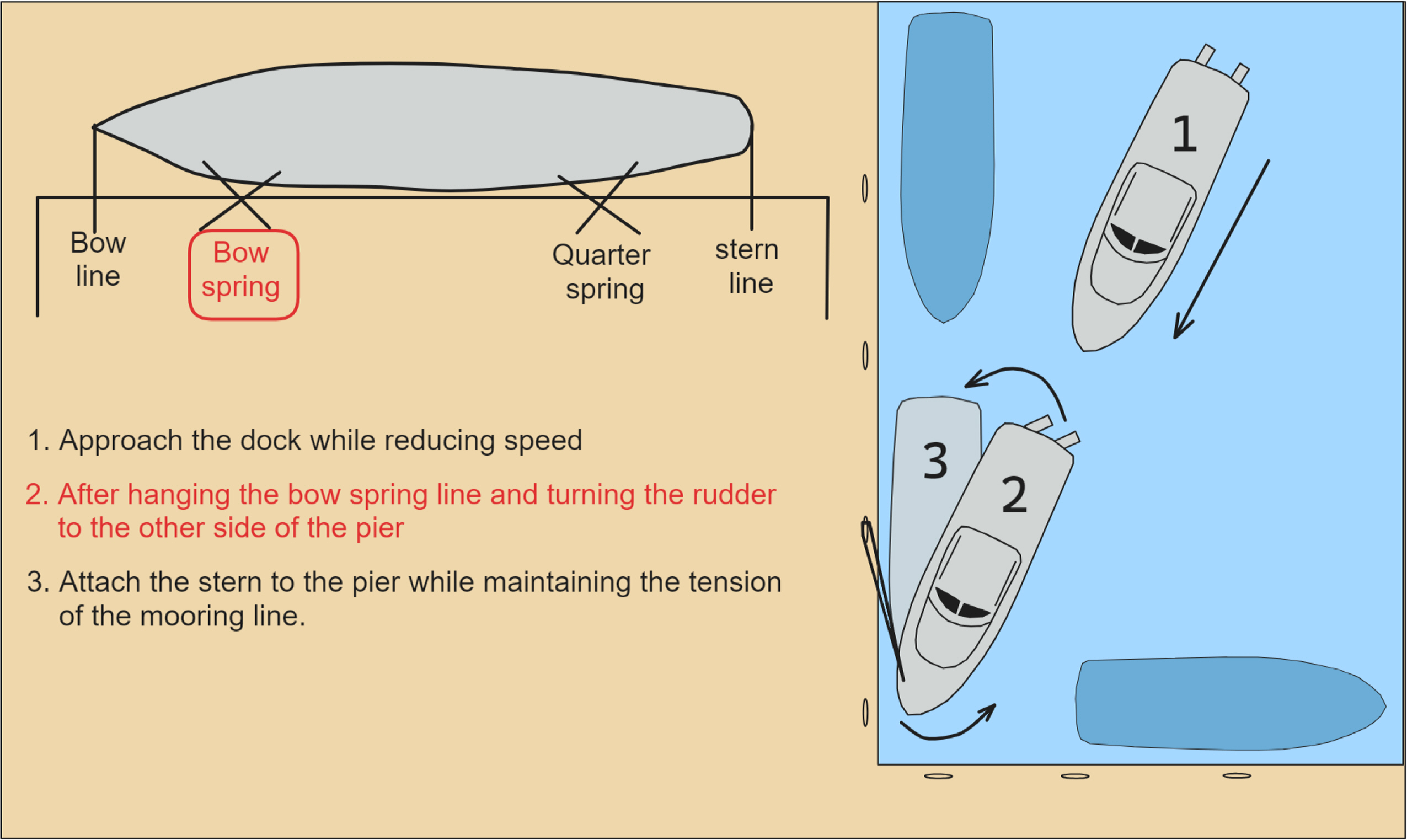
The most dangerous moment for ships during a voyage is when they enter or leave a port. During this time, as the ship approaches the dock, it must reduce speed to avoid collision. On the other hand, the maneuverability of the ship deteriorates when the speed decreases. Thus, large vessels are moored at the dock using a tugboat. Nevertheless, vessels weighing less than 500 t can remain moored at the dock without the assistance of a tugboat, but this requires careful attention. Some ships can use a bow thruster for crabbing, but most can only use the stern thruster to berth at a dock. The most common type of propulsion system used in ships is one that utilizes a screw propeller, as shown in Fig. 1. To compensate for the insufficient bow rotation force during docking, an after-bow spring line is first connected to hold the bow, and the stern is then attached using the engine. This method can produce excessive tension on the after-bow spring line, leading to potentially dangerous situations and making it difficult to use when a vessel is moored in front or behind the dock where it needs to be moored.
Some naval ships, including navy and coast guard ships, use waterjet thrusters instead of screw propellers. The waterjet thruster exhibits superior thrust drift performance to conventional propeller thrusters, and each thruster can be used in different directions. In addition, navy ships demonstrate superior maneuvering performance compared to screw propellers when moving in reverse. Furthermore, in the case of ships utilizing waterjet thrusters, crabbing can be achieved using only the stern thruster despite its low speed. Crabbing refers to the horizontal movement of a vessel without any forward or backward motion or rotation. Crabbing can significantly assist in maneuvering during entry and exit and throughout the movement in the harbor (Lee and Kim 2023). For example, in the situation shown in Fig. 1, no significant increase in the tension of the after-bow spring line will occur if crabbing is possible.
Thus, this paper focuses on a control method that enables crabbing without requiring a bow thruster. The research related to crabbing in ships is as follows. Park and Kim (2013) simulated the control method for crabbing vessels equipped with a bow thruster. Yun et al. (2017) evaluated a method of crabbing in ships using screw propellers and waterjets without the use of a bow thruster. Nevertheless, there was a limitation in that the research findings were only validated through simulations. Pak, Jung, and Yun (2019) precisely analyzed the characteristics of the waterjet thruster. Based on this analysis, the vector sum of forces and the location of the point of action of the forces generated by the thruster were examined. The study demonstrated theoretically how a ship could crab using this information but did not perform verification on real vessels. Park and Lee (2020) conducted a maritime test to examine the crabbing phenomenon in actual ships using a bow thruster. Their study provided a framework for analyzing the results of actual maritime tests, but it had the limitation of only validating crabbing using a bow thruster. Lee and Kim (2023) developed a ship hydrodynamics model to simulate the arrival and departure of a screw propeller ship, but they also modeled the use of a bow thruster.
Theoretical modeling and simulations can assist in suggesting the feasibility of crabbing, but it is crucial to ensure reliability through actual sea trials using real vessels. Therefore, this study conducted a sea trial using a real vessel to test the feasibility of crabbing in waterjet-powered ships, as proposed theoretically.
2. Characteristics of Waterjet-Powered Ships
2.1 Principle of Waterjet Thruster
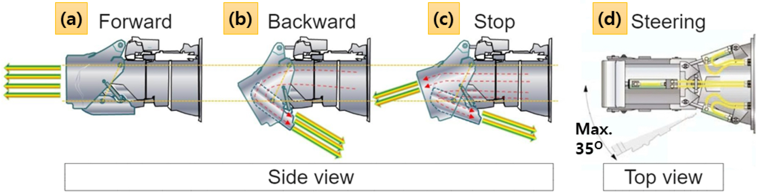
Fig. 2 presents the waterjet thrust method. First, the impeller located inside the hull rotates to draw in seawater by the flush intake. The seawater is then expelled through the bucket installed in the stern via the inlet duct, resulting in forward thrust (Fig. 2(a)). The steering and reverse of the ship are achieved by rotating the bucket left or right and closing the inverse plate of the bucket to propel the ship in the opposite direction by ejecting seawater (Fig. 2(b)).
The steering method ensures that the ship remains in a stop state by positioning the inverse plate of the bucket in the center of the water bucket (Fig. 3(c)), thereby balancing the forward thrust and reverse thrust forces. When the inverse plate of the bucket opens, it moves forward if the forward push is greater than the reverse thrust force (Fig. 3(a)). After the inverse plate of the bucket is fully opened, the engine RPM increases, increasing the rotation speed of the impeller to enhance forward thrust. When the inverse plate closes, the reverse thrust force becomes stronger than the forward thrust, causing the vehicle to move in reverse (Fig. 3(b)). In the case of rotation, steering is performed by changing the bucket direction to the left or right (Fig. 3(d)). The waterjet thruster typically has a rotational range of up to 35° in the left and right directions.
2.2 Characteristics of Waterjet Thruster
The characteristics of a waterjet thruster are as follows. First, the propulsion efficiency at low speeds is lower than conventional screw propeller thrusters, while cavitation is minimized when the impeller rotates at high speeds. Therefore, it is a propulsion method used primarily in high-speed vessels, such as high-speed passenger ships and leisure boats, as it offers high propulsion efficiency at high speeds. Second, the waterjet thruster allows individual control of the installed thrusters to maneuver the vessel, enabling smooth control in both forward and reverse directions. Consequently, it can rotate with a small turning radius and perform lateral movement without requiring a bow thruster. Third, waterjet thrusters enable rapid acceleration and deceleration of a vessel because of the propulsion method using water pressure.
3. Crabbing Mathematical Model of Ships
The center of gravity in the longitudinal direction needs to be determined accurately for the crabbing of a ship. In this case, the force of both waterjet thrusters can be distributed evenly, and the position of the center can be determined by vector decomposition. When the weight of the ship and the position of the center of gravity are determined, the external force generated by the waterjet thruster and the external force available to perform the crabbing are calculated by adjusting the propulsion angle. In this paper, only the force exerted by the ship thruster was considered when constructing the crabbing mathematical model. In contrast, the changes in resistance due to the hull shape or the magnitude and direction of the forces caused by hydrodynamic forces were not considered.
3.1 Estimating the Location of the Center of Gravity of a Ship using the Vector Decomposition Method
The crucial aspect of ship crabbing is to locate the precise center of gravity. The hull will rotate if the exact center of gravity is not found. In the case of a hull, however, the transverse center of gravity is located in the center unless the hull is tilted. On the other hand, determining the exact position of the longitudinal center of gravity is difficult. In this study, the vector decomposition approach was used to determine the longitudinal center of gravity of the hull (Pak et al., 2018).
Fig. 4 presents the crabbing model of the waterjet-powered ship using the vector decomposition method. Two thrusters are utilized in the vector decomposition process, with separate functions for forward and backward propulsion and equal magnitudes of thrust force. This method involves adjusting the rotation angles of each thruster to position the resultant force at the center of gravity. According to the vector decomposition method, by determining the resulting force, as shown in Fig. 4(a), the object will undergo rotational motion if the center of gravity is not aligned with the force. On the other hand, as the resulting force passes through the longitudinal center of gravity of the hull, as shown in Fig. 4(b), the steering moment becomes zero, and the sum of the two equal thrust forces becomes a lateral thrust force acting horizontally at the G point.
3.2 Calculation of Ship Crabbing Control Forces using Force and Moment Equilibrium
A previous study focused on hull crabbing using a ship equipped with two stern thrusters (Yun et al., 2017). On the other hand, this study proposes a method of crabbing for a vessel with three stern thrusters and an additional thruster located in the central part of the hull. When moving to starboard, it was assumed that only the port thruster was steering while the central and starboard thrusters were not rotating. The port thruster generates forces in the x-axis direction, the y-axis direction (crabbing force), and a steering force. For the crabbing of the ship, the forces in the x-axis direction and steering force must cancel each other out. At this moment, the central thruster offsets the force in the x-axis direction, while the starboard thruster offsets the steering force. While it is possible to obtain a greater crabbing force using all three thrusters, in practice, it is more common to use only one thruster for crabbing. This is because the stern thruster, located further away from the center of gravity of the hull, generates a significant crabbing force that needs to be offset by an increased moment.
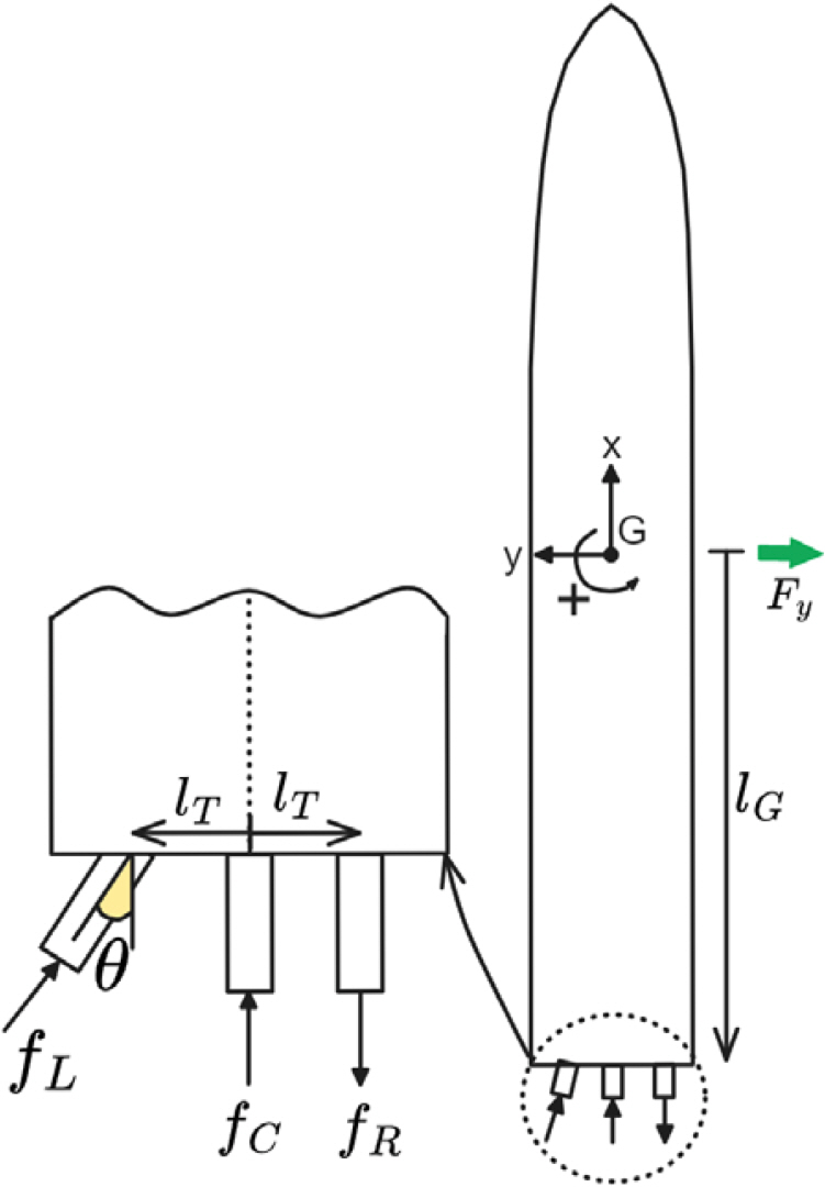
Fig. 5 shows the positions of the thrust force and the longitudinal center of gravity. The thrust force of the port thruster is denoted as fL . The thrust force of the central thruster is denoted as fC, and the thrust force of the starboard thruster is denoted as fR . The angle of the port thruster is represented by θ, and the transverse distance from the thruster to the centerline is denoted as lT . The distance from the stern to the longitudinal center of gravity is denoted as lG . The equilibrium equations for the force and moment required for a ship to move only in the horizontal direction without rotating or moving vertically were derived using only the thrust force of the ship and no other external forces, such as currents or wind.
First, the thrust force values of the central thruster ((fC ) and the starboard thruster ((fR ) of the hull were calculated. The equations of motion for hull crabbing can be solved by expressing the given values and the values to be found as follows:
For crabbing of the hull, the X-axis translational motion must not occur. Thus, the resulting force in the x-axis direction of the hull must be equal to zero. This can be expressed as the following equation.
Next, the sum of moments when the hull rotates around the z-axis must equal zero. This can be expressed as the following equation.
The equations of equilibrium for these two forces yield the following equations for the forces exerted by the central and starboard thrusters:
Therefore, the magnitudes of the central thruster and starboard thruster forces can be determined if the angle and force of the port thruster when moving starboard are known.
4. Sea Trials with Real Ships
4.1 Specifications of a Navy Ship
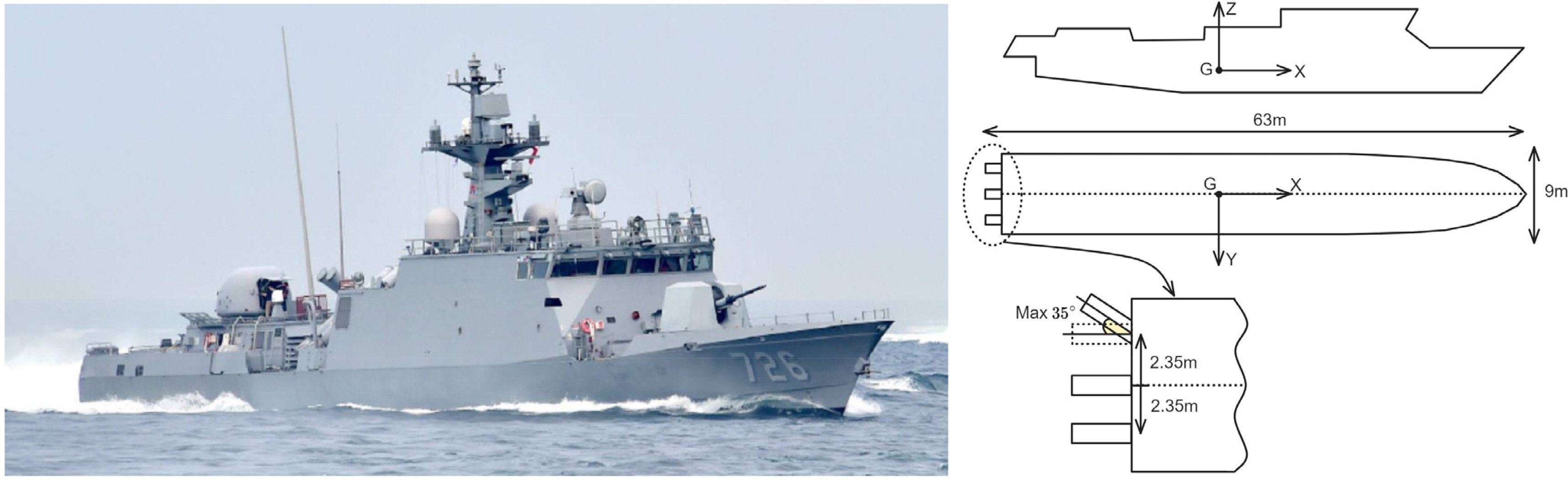
The vessel used in this study was a patrol killer guided missile (PKG) ship operated by the Navy. The PKG is a navy ship produced to defend the coast of South Korea. Fig. 6 and Table 1 present the ship specifications that do not pose a security concern. PKG has implemented a waterjet propulsion system to enable high-speed maneuverability in the coastal waters of South Korea, which are filled with fishing nets and obstacles. The PKG uses three waterjet thrusters for propulsion and maneuvering. The waterjet thrusters on the left and right sides are powered by diesel engines, while the centrally installed thruster is used for high-speed navigation and operates on a gas turbine.
4.2 Crabbing Method using Three Stern Thrusters
The stern thruster of PKG consists of a total of three units. Diesel engines power the left and right sides, while a gas turbine powers the central thruster. Typically, the gas turbine is operated during high-speed navigation. When located at the center of the hull, without using a rudder, it only generates forward or backward force and does not provide rotational force. This study tested the crabbing method proposed in section 3 using three thrusters, including a central thruster and two thrusters on the left and right sides of the hull.
The transverse distance (lT) from the center of the hull to the thruster was 2.35 m. The center of gravity (G) of the vessel was assumed to be located on the centerline of the hull, as there was no lateral inclination. Subsequently, the method of determining the longitudinal center of gravity of the hull described in section 3.1 was applied to calculate the center of gravity of the non-rotating PKG. As a result, the distance (lG) from the longitudinal center of gravity to the stern thruster was approximately 27.5 m.
The angle of the port thruster can be adjusted independently when the vessel is crabbed using three stern thrusters. The power and angle of the port thruster determine the power size of the central and starboard thrusters. Thus, in this experiment, the rotation angle of the port thruster was adjusted to 10°, 15°, 20°, and 25° to generate the crabbing motion of the vessel according to the continuously changing marine environment. Table 2 lists the power changes of the central and starboard thrusters in response to changes in the thruster angle. The unit of measurement used was knots because the thrust force of the waterjet thruster is determined by the flow velocity of the expelled water during propulsion.
4.3 Test Method and Conditions
The crabbing test was conducted under a stable steady state of sea conditions. It is essential to record the hull movements, such as the rotation angle of the bow and the forward and backward velocities, in a consistent chronological order (Park and Lee, 2020). Conducting tests in areas without wind and current is ideal for maritime conditions. On the other hand, wind and current are always present due to the inherent characteristics of maritime vessel testing. Therefore, this study conducted a maritime test in the presence of currents and wind, considering the weather conditions that would minimize their impact. The sea trial was conducted in a state where the current direction was transverse (beam current) to minimize the influence of external forces. Table 3, lists the sea trial conditions.
The sea trial took place on July 21, 2023, at Jinhae Port. During the test, the wind speed was equivalent to Beaufort 3, ranging from 3 to 6 m/s, and the current speed was 1.2 m/s. Because the current was around 90° at the start of the trial, the ship was brought to a stop, and a crabbing test was performed by aligning the bow angle to 180° and moving starboard. The following values were measured to determine accurately if the ship was crabbing. The engine RPM, tilt angle, wind direction, and speed, ship heading, GPS speed, and direction were recorded at three-second intervals. Each system could not be interconnected owing to the nature of the navy ship, and it was not possible to install separate measuring equipment or computers for security reasons. Thus, a method was employed in which the data values that needed to be measured were recorded by individuals at three-second intervals. Accuracy was ensured by measuring the time log of the recorder simultaneously using stopwatches, with four individuals collecting and recording the data. The number of individuals measured and the recorded content for each individual are shown in the table below.
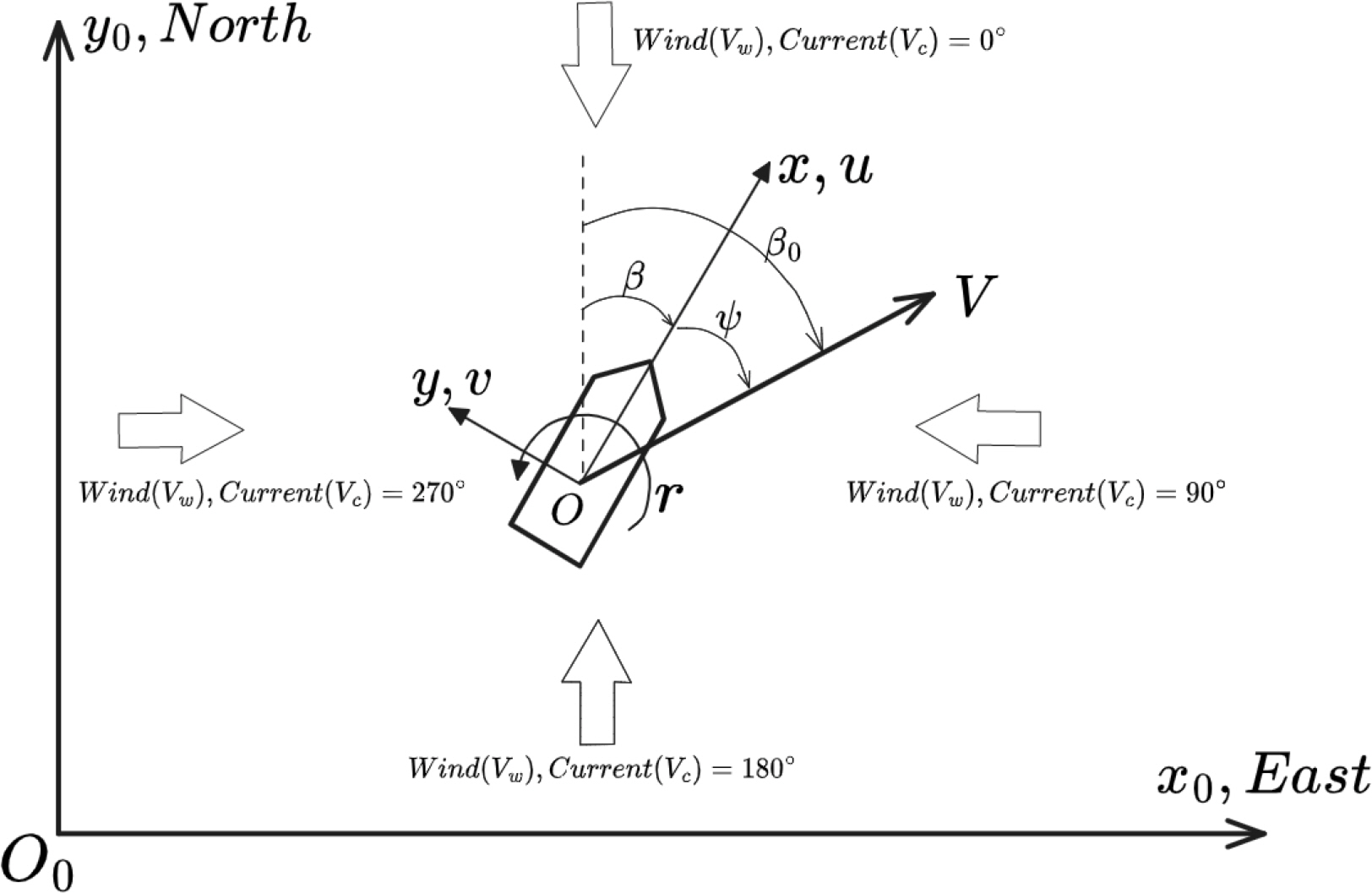
Fig. 7 presents the coordinate system used in this study. There are x0 and y0 axes in the Earth-fixed coordinate system, and x and y axes in the ship-fixed coordinate system. In the geocentric coordinate system, the velocity of a ship was defined as V, while the velocity in the ship-fixed coordinate system was defined as u and v for the x and y directions, respectively. The rate of turn (ROT), which is defined as the speed at which a ship rotates around the origin O in the fixed coordinate system, is denoted by r. The bow angle (β) is defined as the angle formed between the x0 axis of the Earth-fixed coordinate system and the x-axis of the ship-fixed coordinate system. In the Earth-fixed coordinate system, the speed of the ship is defined as V. The angle between the direction of the ship speed V and the x0 axis of the Earth-fixed coordinate system is defined as β0. The angle between the direction of the ship speed and the x-axis of the ship-fixed coordinate system is defined as the drift angle ψ. The wind and current are defined as 0°, 90°, 180°, and 270° when coming from the north, east, south, and west, respectively.
The measurement interval of this test data was three seconds. The position of a ship measured by GPS is indicated by its latitude and longitude coordinates, while the speed of the ship is referred to as the ground speed. Four observers were deployed to measure data from the ship, with each observer synchronizing their time with each other and simultaneously initiating observations to measure and record the data.
The purpose of this sea trial was to test crabbing. Although the transverse speed of the vessel is the most crucial factor, the longitudinal speed should also be recorded. The vector velocity of a ship can be measured, but it is not possible to measure the transverse and longitudinal velocities of the ship directly in a local coordinate system. Therefore, it is necessary to derive the transverse and fore-aft velocities from the measured vector velocity. The drift angle (ψ) must be determined to achieve this. The drift angle (ψ) can be obtained by subtracting the gyro course (β) of the ship from the direction of the ship velocity (β0), as shown in Eq. (5).
5. Test Results and Analysis
5.1 Rotation of the Hull
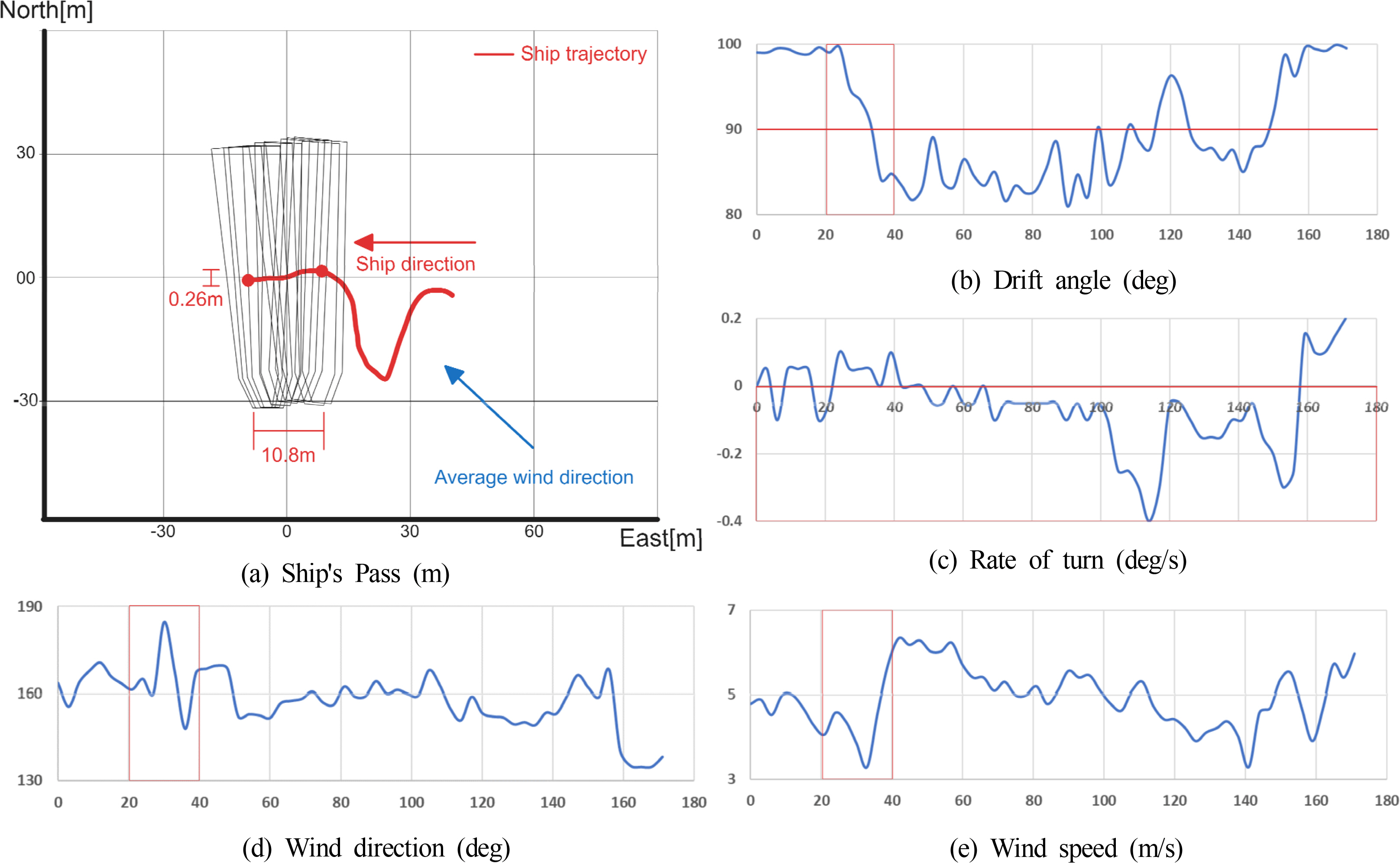
The graph in Fig. 8 represents the track of the measured vessel during the test, as well as the drift angle (ψ), ROT, wind direction, and wind speed. The x-axis on this graph represents time. Fig. 8(a), which depicts the ship trajectory, shows that the hull gradually rotates and moves from side to side due to the influence of environmental force (wind). The drift angle (ψ) observed in Fig. 8(b) exhibited a difference of 10° to the left and right from 90°. In addition, while the hull moved laterally by 10.8 m, it also moved slightly longitudinally by 0.26 m. Furthermore, in Fig. 8(c), the hull rotated by approximately 0.4°, albeit very slowly.
The ship in this test swayed from side to side during crabbing, possibly because there was no bow thruster. The ratio of the length to width of the hull of the ship used in the test was 7:1. Thus, the rotational force generated by the stern thruster greatly exceeds the horizontal force of the hull to move transversely. The point at which this balance of forces is achieved has a very narrow radius, and the ship will start to rotate if the equilibrium point deviates even slightly.
Furthermore, in the ocean, there are continuous environmental forces such as waves, currents, and wind. In particular, the equilibrium point for the ship to move laterally also changes constantly due to the continuous changes in both the direction and magnitude of the wind. Because of these influences, individuals operating ships must anticipate the range of angles at which the stern thruster achieves a balance of forces and continuously adjust the thruster within that range to maintain a dynamic balance. On the other hand, it becomes challenging to maintain equilibrium when the direction or intensity of the wind changes abruptly. In Fig. 8 (d) and (e), it is evident that there is a significant change in both the direction and intensity of the wind within the 20- to 40-s interval in this experiment. Hence, the drift angle (ψ) of the hull exhibits the most dramatic variation in the 20- to 40-s interval.
Lastly, as shown in Fig. 8(c), the ROT is predominantly distributed in values smaller than 0°. Therefore, the ship primarily undergoes left bow rotation (counter-clockwise rotation) because of the wind direction. In Fig. 8(a), the prevailing wind direction during the experiment blew from the southeast, ranging between 130° and 170° azimuth. This wind blew from the port bow from the viewpoint of the hull. Because the PKG is a waterjet-propelled ship, its hull beneath the water surface is flat. Furthermore, the hull is equipped with stealth capabilities, and the structure of the stern is larger than that of the bow, resulting in the stern being more susceptible to the influence of wind. Therefore, the ROT was less than zero because the port stern was pushed by the wind, subjecting the hull to a left bow rotation.
5.2. Determining the Success of Crabbing
Finally, the crabbing motion was defined to determine the success of the sea trial. In general, for a ship with a bow thruster, the magnitude of the drift angle (ψ) should be small at 90°, and the forward and backward velocities should be small compared to the transverse velocity to determine normal crabbing. The test results showed that the ROT was insignificant, while the drift angle (ψ) fluctuated within a range of 10° in both directions. In this trial, however, it is challenging to fully control the rotation of the hull because of the absence of a bow thruster on the vessel, and the reliance solely on the stern thruster for crabbing. Furthermore, the vessel used in this trial does not have crabbing as its primary objective. The crabbing test was conducted to verify the ability to perform crabbing during port entry or exit or in emergencies, even in the absence of a bow thruster. Thus, in this trial, the focus was placed on determining the success of the crabbing test by assessing the longitudinal displacement in relation to the actual transverse displacement of the vessel. The test results indicate that a cumulative distance of 10.8 m was covered in the lateral direction over 180 s, while a maximum displacement of 0.26 m was achieved in the longitudinal direction (Fig. 9(a)). As it moved 0.4%, considering the length of the ship is 63 m, the crabbing test using only the stern thruster of the waterjet-powered ship was considered to be successful. Furthermore, the longitudinal velocity was virtually nonexistent, with a maximum of 0.02 m/s (Fig. 9(b)).
6. Conclusion
This study conducted a steering experiment on a real ship scale to verify the crabbing performance of a waterjet-powered ship using only the stern thruster. Data were collected from a PKG navy ship at a level that did not compromise security, and the collected data was used for analysis after undergoing a security review. Owing to security concerns inherent to navy ships, installing measurement equipment throughout the data collection process was not possible. As a result, the measurements were performed by humans, which did not impact the data analysis. The results of the sea trial indicated that the hull rotation was difficult to control using only the stern thruster, but the lateral movement of the hull was sufficiently achievable, which is a significant finding. Based on the analysis, the PKG is capable of crabbing motion at a maximum speed of 0.15 m/s under the Beaufort 3 sea condition.
The limitation of this study lies in the reliance on the operator's ability to control the hull dynamically. Therefore, future research will focus on developing a simulation model for automatically adjusting the rotation angle and power of waterjets to enable the crabbing motion of ships using GPS and DGPS.