Nomenclature
amn: General coefficient
b: Breadth of a rectangular grillage plate
E: Elastic modulus
Ir: Moment of inertia of longitudinal stiffeners
Is: Moment of inertia of transverse stiffeners
l: Length of a rectangular grillage plate
m, n: Wave numbers
P: Load per unit area on a rectangular grillage plate
r: Number of longitudianl stiffeners
s: Number of transverse stiffeners
w: Deflection of a rectangular grillage plate
ν: Poisson’s ratio
σallow: Allowable stress
1. Introduction
With the increasing importance of ocean environments, the International Maritime Organization (IMO) is strengthening regulations on greenhouse gas emissions at sea, such as by adopting the 2023 IMO Greenhouse Gas Strategy to achieve carbon neutrality in international shipping by 2050. To achieve this, technologies are being actively developed to minimize environmental pollutants emitted from ships using fossil fuels, alongside efforts to use eco-friendly renewable energy to power ships. However, the stability of renewable energy supply is limited, and the generation costs are high. Considering the increasing size of super-large ships, large amounts of energy are needed. Consequently, there is a growing interest in nuclear energy as an alternative energy source for ship operations.
While ships powered by fossil fuels have established systematic design rules based on abundant design and operating experience, for ships using nuclear energy for propulsion, it is difficult to find domestically driven design examples. Therefore, it is necessary to prioritize research on developing technology that converges nuclear and shipbuilding industries for future ship design using shipboard reactors.
Most studies on applying nuclear propulsion systems to ships deal with the selection of ship types that can increase the efficiency of reactor installation using economic analysis, or concepts related to the placement of nuclear propulsion systems within the hull based on risk assessment. Gravina et al. (2013) proposed the concept of a modular vessel composed of a propulsion module with a reactor and a cargo hold module for cargo loading, and conducted research on its application to large container ships. Gil et al. (2014) performed an economic analysis for various dedicated cargo ships, selected container ships as the target ships for reactor installation, and investigated the optimal placement of the reactor system in the engine room compartment within the hull. In similar research based on risk assessment associated with reactor operation, Hirdaris et al. (2014) conducted a conceptual design study applying a small modular reactor (SMR) to a Suezmax tanker. Meanwhile, research on marine nuclear power generation using reactors has also been conducted. Lee et al. (2015) investigated structural platforms at sea where reactors are installed, and extensively researched the types, sizes, and placement methods of the reactors to be applied to them, as well as the cooling system and other components.
It is evident that the focus of the selected literature differs from the focus of this study—the influence of the operating environment of the reactor on the surrounding structures within a vessel once installed inside the vessel. Therefore, from the perspective of the structural design of the vessel, we first analyzed the operating environment of the reactor installed on the ship as part of the development of convergence technology between the nuclear and shipbuilding industries. This study focused on changes in material properties of the hull structural steel due to neutron irradiation—which is not considered in conventional fossil fuel-based ship design—and its impact on the responses of internal structural components where the reactor is installed.
In nuclear operating environments, steel is exposed to neutron energy, creating defects such as those resulting from the generation of knock-on atoms from the lattice atoms that make up the steel structural material. The generated knock-on atoms move within the lattice, causing other atoms to be knocked out and producing a chain reaction that leads to the creation of numerous knock-on atoms (Knaster et al., 2016). This ultimately changes the mechanical properties of the steel, leading to phenomena revealed in related research such as radiation hardening and embrittlement (Hong, 2012). The tensile strength of steel exposed to continuous neutron irradiation during reactor operation has been found to increase, while the maximum absorbed energy and fracture toughness are reduced, as proved by Charpy notch impact tests. These characteristics of the neutron-irradiated steel are connected to a reduction in the elastic modulus and Poisson’s ratio (Ahn et al., 2002). Therefore, the structures inside the containment of the hull where the reactor is installed will be affected by such changes in steel properties due to neutron energy. Consequently, they will show different structural responses compared to similar structures of a fossil-fuel-based propulsion system inside the hull. This is an important consideration for structural designers.
We used DH36 high-strength steel—a representative shipbuilding and marine steel for stiffened-plate structures—as an example of the material constituting the structure around the reactor of the ship exposed to neutron irradiation. The extent of the changes in the properties of the DH36 steel irradiated with neutrons was determined using experimental data and theoretical estimates of neutron-irradiated steel used in terrestrial reactor facilities (Straalsund and Day, 1973). Through this, we derived scenarios with varying properties of DH36 steel such as elastic modulus, Poisson’s ratio, and allowable stress values. The structural response analysis of the configured DH36 steel-based stiffened plate was performed using the grillage-structure theory and finite-element analysis methods, calculating the load-bearing capacity, strength, deflection values, etc., against transverse loads assuming the support load of the reactor of the ship. Through this, we quantitatively analyzed the impact of neutron irradiation occurring in the reactor operating environment on the structural responses of the hull structure.
2. Material Property Variation of Hull Steel due to the Neutron-Irradiation Phenomenon
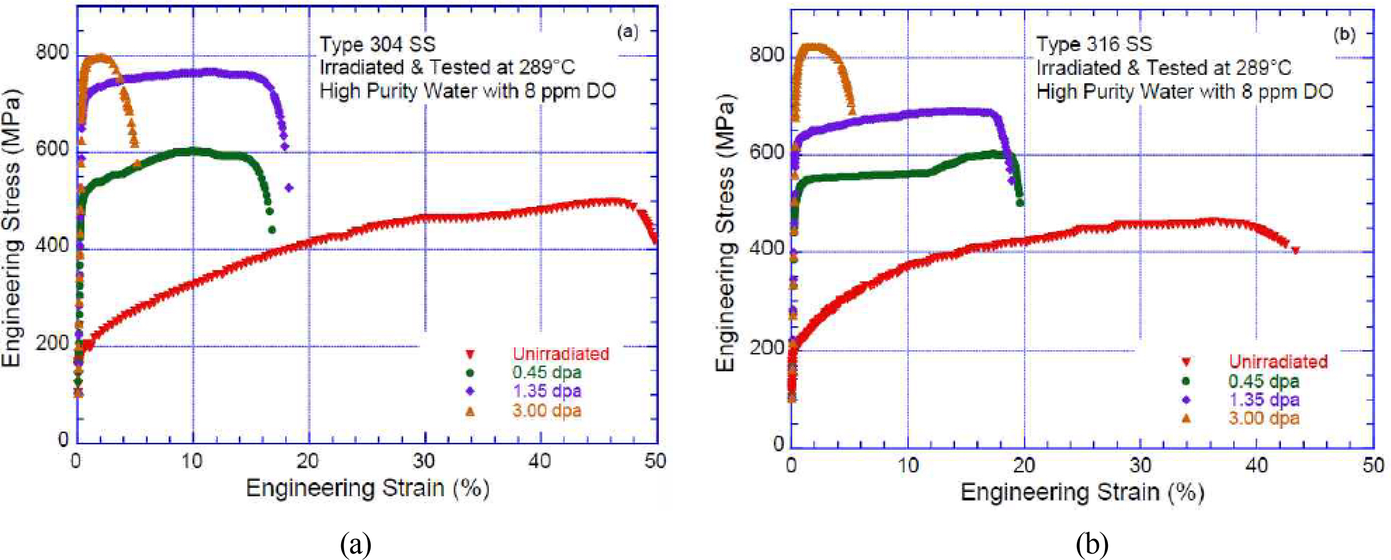
According to studies on neutron-irradiated steel of terrestrial nuclear power plants, the stress-strain curve of irradiated steel shows a different correlation from that of non-irradiated steel (Jhung et al., 2013). Fig. 1 shows the nominal stress–nominal strain curves of Type 304 and Type 316 stainless steel subjected to various neutron-irradiation amounts ranging from 0.45 to 3 dpa (displacements per atom). As the neutron irradiation increases, the tensile strength and yield stress of the steel increase, while the ductility decreases. The hardening and embrittlement of steel due to neutron irradiation becomes more evident when comparing the nominal stress–nominal strain curves of non-irradiated and irradiated steel. Although not shown in Fig. 1, studies report that the yield stress of irradiated steel at about five dpa is up to five times higher than that of non-irradiated steel (Jhung et al., 2013).
Straalsund and Day (1973) used ultrasonic techniques to measure the changes in elastic modulus and Poisson’s ratio of neutron-irradiated Type 304 stainless steel, and theoretically predicted the rate of change in these material properties as upper and lower bounds. In their theoretical predictions, they calculated the reduction rates of the elastic modulus and Poisson’s ratio as functions of void volume, ranging from a minimum of 1% to a maximum of 10%. The experimentally determined and theoretically estimated changes in the elastic modulus and Poisson’s ratio for neutron-irradiated Type 304 stainless steel closely matched. This implies that as the neutron irradiation increases, the void volume fraction increases, while the elastic modulus and Poisson’s ratio decrease. The authors concluded that applying these results is feasible for structural steel with different crystal structures (body-centered cubic (BCC) and face-centered cubic (FCC)), where the void volume changes due to neutron irradiation. Additionally, Hong (2012) found that the increase in tensile strength and embrittlement phenomenon was stronger in the neutron-exposed BCC and FCC crystalline structured steel than in the non-irradiated identical steel, by simultaneously comparing the nominal stress–nominal strain curves of the irradiated two types of steel.
In this study, the stiffened-plate structure inside the hull containment structure used as an example was assumed to be located outside the reactor pressure vessel and subjected to a relatively low level of neutron irradiation, corresponding to the initial stage of void volume fraction. Based on the research results of Straalsund and Day (1973) and other preceding studies on neutron-irradiated steel (Ahn et al., 2002; Hong, 2012; Jhung et al., 2013), we investigated the rates of change of the elastic modulus, Poisson’s ratio, and allowable stress of DH36 steel as the material property variation scenarios, as shown in Table 1.
Where, MPC_0 represents the properties of non-irradiated DH36 steel with a density of 7,850 kg/m3 (Korean Register, 2020; RMRS, 2018), and MPC_1 to MPC_6 show the changes in material properties at void volume fractions ranging from 1% to 3%. The reduction rates of the elastic modulus were 2%, 4%, and 6%, and those of Poisson’s ratio were 0.4%, 0.7%, and 1%, respectively. The changes in the allowable stress of neutron-irradiated DH36 steel were only considered for MPC_4 to MPC_6; these were increased by 25%, 50%, and 100%, respectively.
3. Stiffened-Plate Structures and Their Analytical and Numerical Solutions
The details of the stiffened-plate structures inside the hull containment structure, previously mentioned as the example, were determined by referring to the stiffened plate used in related studies (Kõrgesaar et al., 2018; Nam, 2019). The referenced stiffening plate meets the buckling requirements of FSICR (2008) and IACS (2016) and is composed of flat bars, web frames, and stringers. Based on the above, two stiffened-plate structures named Case A and Case B were considered, both of which commonly employ multiple Tee-section steel stiffeners in the transverse and longitudinal directions. Regarding their differences, the stiffened-plate structure of Case A had the same dimensions for both transverse and longitudinal stiffeners, while the stiffened-plate structure of Case B had different dimensions for the transverse and longitudinal stiffeners. The specifications of the two stiffened-plate structures are shown in Table 2; the dimensions of the stiffeners are denoted in the order of web thickness × web height × flange thickness × flange width.
3.1 Analytical Solutions for Laterally Loaded Flat Grillage Plates
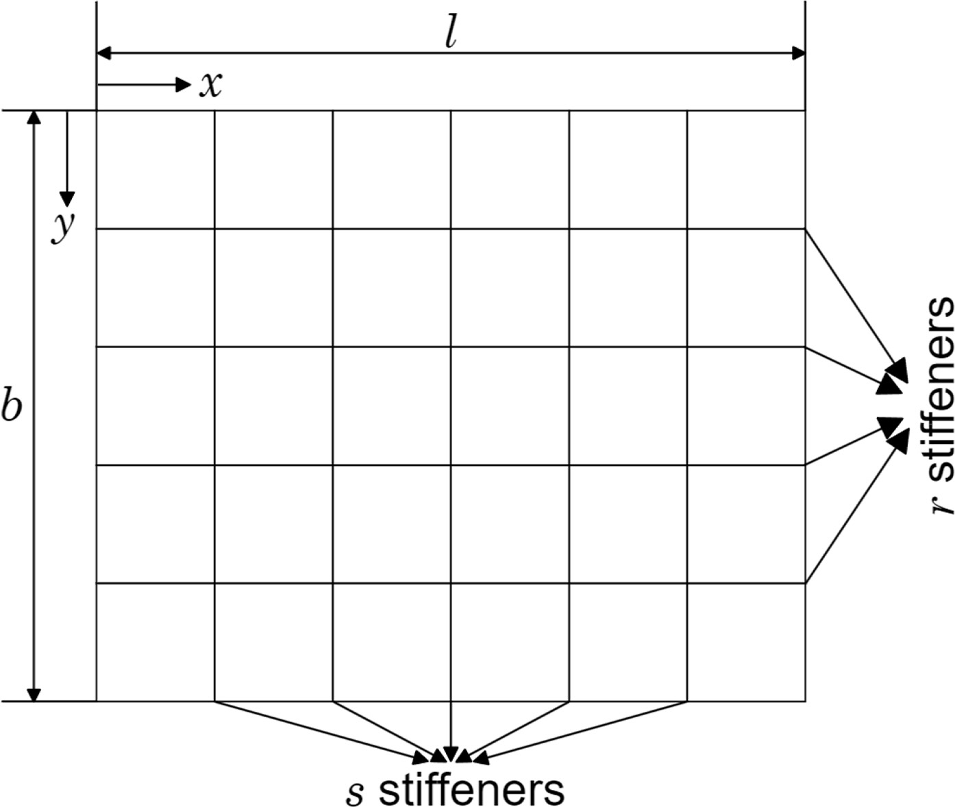
As shown in Fig. 2, we consider a simply supported stiffened-plate structure with s evenly spaced stiffeners in the length direction l, and r evenly spaced stiffeners in the width direction b. The moment of inertia for the longitudinal stiffeners is Ir, and that for the transverse stiffeners is Is . If the deflection in the x, y plane of the stiffened-plate structure caused by the bending load is denoted by w, the deflection curve of the stiffened-plate structure can be obtained using the following equation.
The above equation can be solved by calculating the bending deformation energy of the stiffener system and equating it to the work done by the load. The deformation energy of a single longitudinal stiffener can be expressed as follows.
In Eq. (2), the value of y corresponds to a specific stiffener, and the corresponding equation for the p-th stiffener is expressed as Eq. (3).
Therefore, the deformation energy is expressed as Eq. (4).
By using Eq. (4), the total deformation energy for all the stiffeners placed in the same direction is,
The bending deformation energy for all the stiffeners placed in the direction orthogonal to the stiffeners represented in Eq. (5) can be similarly expressed as Eq. (6).
Therefore, the total deformation energy for all longitudinal and transverse stiffeners installed on the stiffened plate can be calculated using Eq. (7).
If the load per unit area applied to the stiffened plate is P, the work done by this load is expressed as Eq. (8).
The general coefficient amn can be found by equating the general terms of Eq. (7) and Eq. (8) as in Eq. (9).
Since no assumptions have been made regarding the equation for the applied load P, the coefficient amn obtained from Eq. (9) can be used in any distributed load acting on a simply supported symmetric stiffened-plate structure. As most load distributions of interest are uniformly distributed loads, if a stiffened plate with a symmetrical distribution load is considered, the coefficient amn can be obtained using Eq. (10).
Therefore, the final equation regarding the deflection deformation of the stiffened plate under bending load is Eq. (11).
From Eq. (11), the bending moment equations for the p-th longitudinal stiffener and the q-th transverse stiffener can be obtained as follows.
For the bending moment for the p-th longitudinal stiffener,
For the bending moment for the q-th transverse stiffener,
Finally, using the bending stress equation, the tensile and compressive stresses for the p-th longitudinal stiffener and the q-th transverse stiffener can be determined individually (Clarkson, 1965).
3.2 Finite-Element Solutions for Laterally Loaded Stiffened Plates
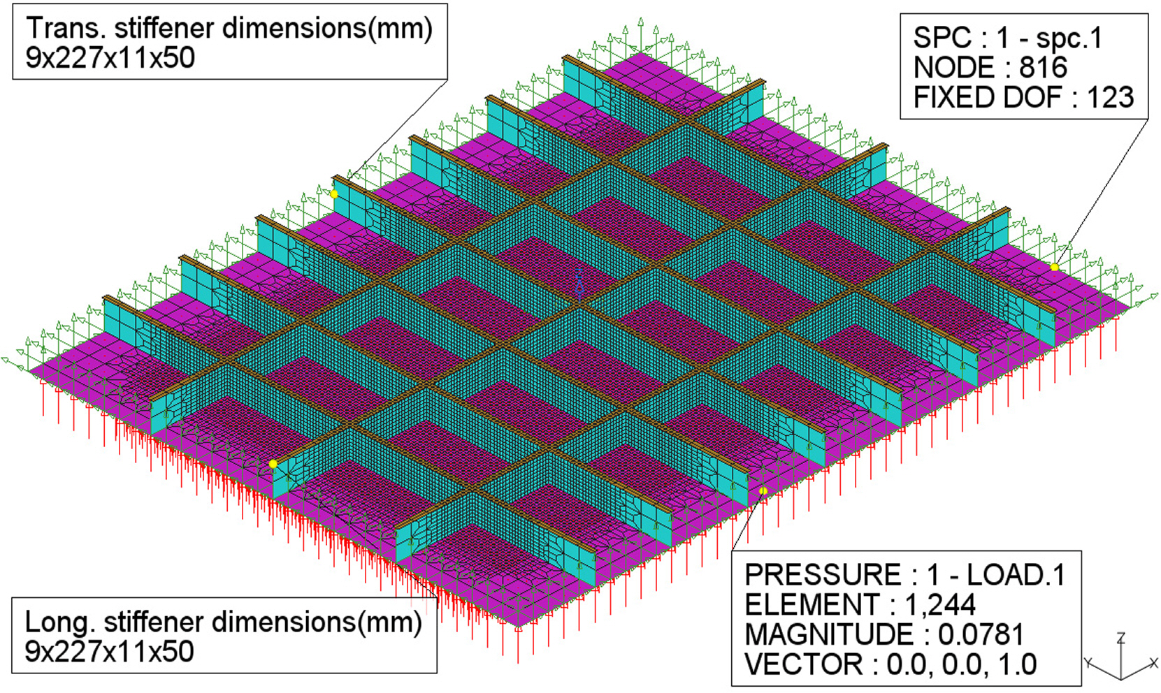
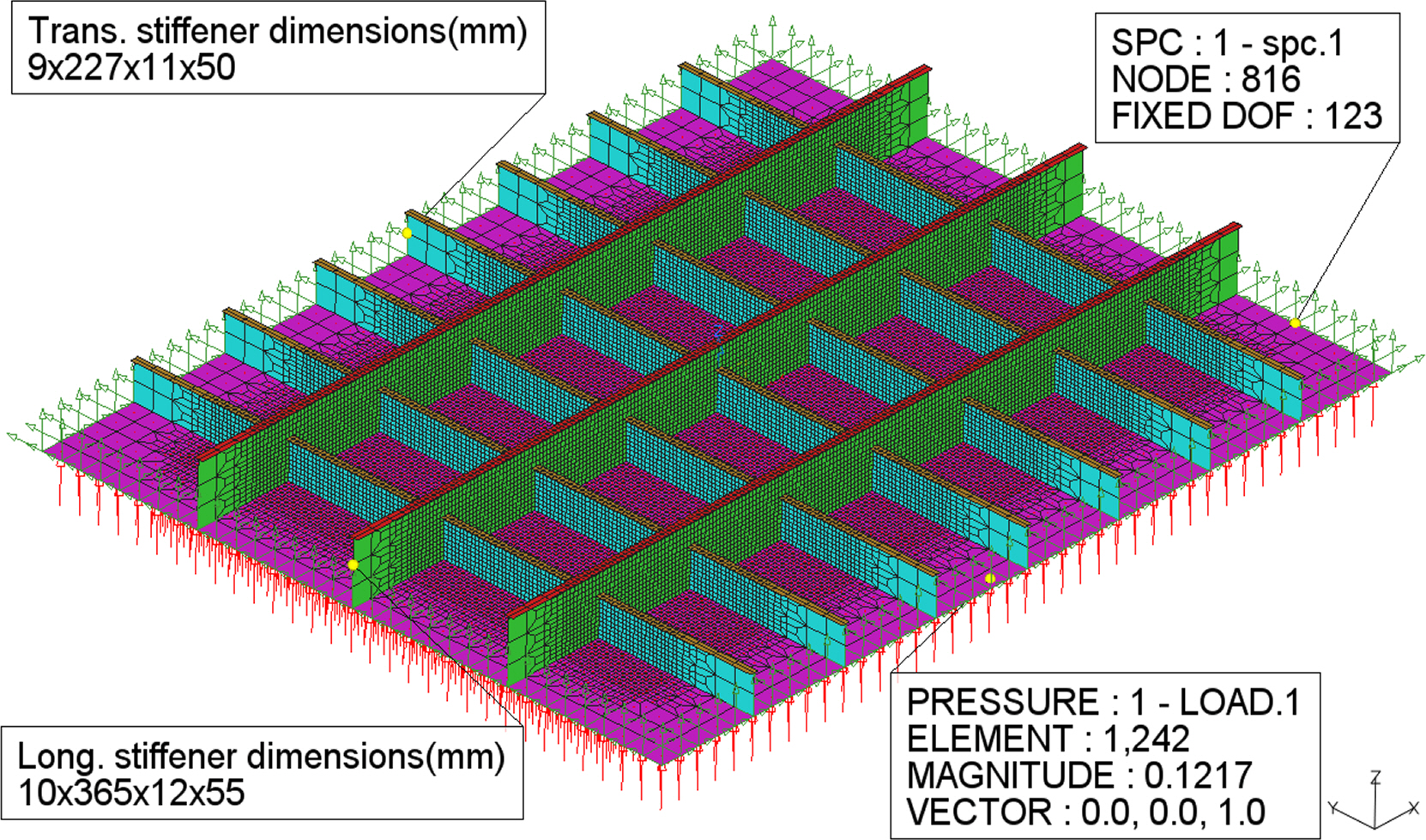
We developed finite-element models based on the specifications of Cases A and B stiffened-plate structures shown in Table 2. The geometries of these stiffened-plate structures, the dimensions of the stiffeners, and the applied boundary and load conditions are shown in Figs. 3 and 4.
Patran and Nastran programs of MSC—general-purpose finite-element analysis packages—were used to develop the finite-element models. MSC Nastran is a structural analysis and multi-disciplinary integrated solver, and MSC Patran is a pre- and post-software for finite-element analysis that supports the entire process of finite-element modeling, from mesh division to setting analysis conditions and post-processing results.
QUAD4 elements with four nodes per element were used to develop the finite-element models 2D shell elements widely used in the analysis of quadrilateral membrane-bending planar structures and provided in Patran. The mesh density was increased to 25 mm for the central part of the structure, where maximum deformation was expected, whereas the remainder was divided into elements of 125 mm; this was based on the element size used in previous research (Kõrgesaar et al., 2018) on stiffened plates when developing a finite-element model. In the finite-element model of Case A stiffened-plate structure, 39,664 QUAD4 elements were used, whereas in the finite-element model of Case B stiffened-plate structure with relatively larger longitudinal stiffeners, 42,406 QUAD4 elements were used. The load was applied perpendicularly to the plate, allowing the longitudinal and transverse stiffening systems to support the plate vertically, and simple support was implemented by constraining displacements in the x-, y-, and z-axis directions (UX, UY, UZ) along the sides of the stiffened-plate structure.
4. Structural Response Analysis of Stiffened-Plate Structures in the Reactor Operation Environment
4.1 Structural Response Analysis of Stiffened-Plate Structures Using the Analytical Solutions Considering the Neutron-Irradiation Phenomenon
The grillage-structure theory summarized in the previous section was implemented in Fortran programming language. The bending load applied to the stiffened-plate structures was gradually increased until the allowable stress value of DH36 steel was met. First, the calculated results for the neutron non-irradiated Cases A and B stiffened-plate structures are shown in Table 3. The stiffened-plate structure of Case A supported a bending load of up to 78.1 kPa, at which point the maximum deflection was 14.13 mm, and the maximum bending stress was 354.84 MPa. The Case B stiffened-plate structure supported a bending load of up to 121.7 kPa, at which point the maximum deflection was 14.35 mm, and the maximum bending stress was 355.08 MPa.
For the Case A stiffened-plate structure, in which the changes in the material properties of the steel were considered (Table 4), the elastic modulus and Poisson's ratio decreased, and the changes in allowable stress were not considered. The stiffened plates in the MPC_1 to MPC_3 scenarios supported loads up to 78.1 kPa, with no change in maximum bending stress at 354.84 MPa, but the maximum deflection increased to 14.62 mm, 14.72 mm, and 15.04 mm, respectively. Next, in the MPC_4 to MPC_6 scenarios, where the allowable stress was further increased by 25%, 50%, and 100% in the MPC_1 to MPC_3 scenarios, the stiffened plates were able to support loads in the order of 97.67 kPa, 117.2 kPa, and 156.27 kPa, and the maximum bending stress increased in the order of 443.75 MPa, 532.48 MPa, and 709.99 MPa. The maximum deflection also increased in the order of 18.04 mm, 22.09 mm, and 30.09 mm.
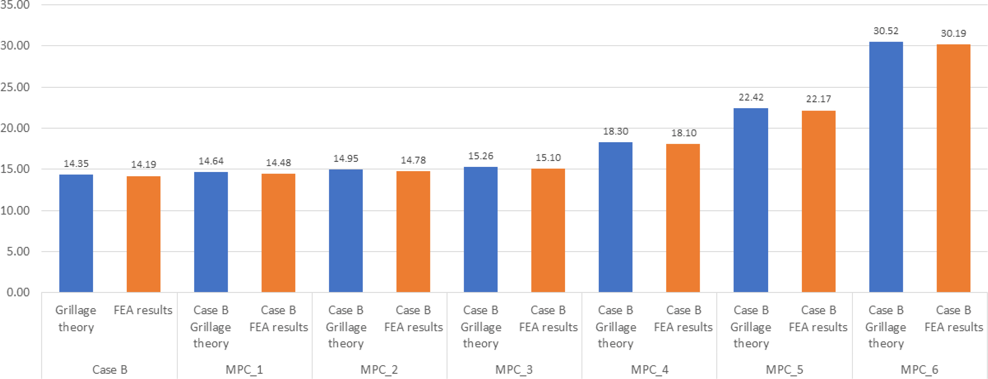
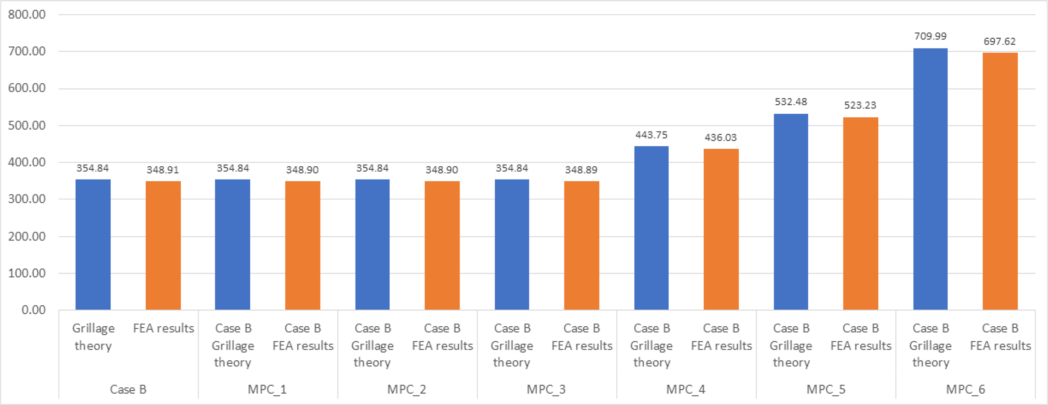
Subsequently, for the stiffened-plate structure of Case B considering variations in steel material properties (Table 5), the maximum bending load of the stiffened plate was the same (121.7 kPa) in scenarios MPC_1 to MPC_3, and the maximum bending stress did not change (355.08 MPa); however, the maximum deflection increased to 14.64 mm, 14.95 mm, and 15.26 mm, respectively. On the other hand, for the stiffened plate under scenarios MPC_4 to MPC_6, the maximum support bending load increased in the order of 152.09 kPa, 182.51 kPa, and 243.34 kPa, and the maximum bending stress increased in the order of 443.75 MPa, 532.5 MPa, and 709.98 MPa, while the maximum deflection increased in the order of 18.3 mm, 22.42 mm, and 30.52 mm.
For the above two types of stiffened-plate structures, regarding the ratio of deflection per applied load, the ratio in scenarios MPC_1 to MPC_3 was nearly equaled that in scenarios MPC_4 to MPC_6 as the analysis was performed based on the allowable stress value of the steel.
4.2 Structural Response Analysis of Stiffened-Plate Structures Using the FE Numerical Solutions Considering the Neutron-Irradiation Phenomenon
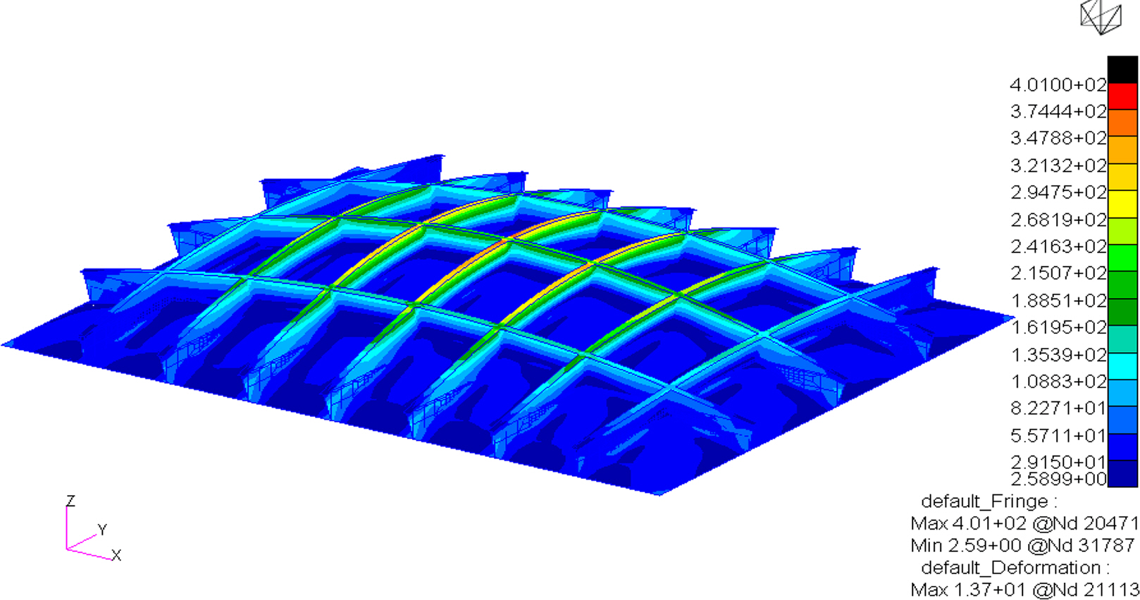
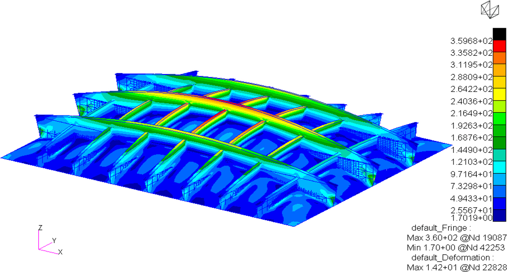
This section summarizes the structural response analysis results based on the allowable stress of DH36 steel using the finite-element models for Cases A and B stiffened-plate structures. By comparing with the results obtained using the grillage-structure theory for the same stiffened-plate structures, the accuracy of the developed finite-element models can be confirmed, and the structural deformation of the stiffened plates can be simulated. The deformation of Cases A and B stiffened-plate structures under bending loads is shown in Figs. 5 and 6, respectively.
The analysis results for Case A stiffened-plate structure are summarized as follows. Owing to the characteristics of the simply supported boundary conditions of the stiffened plate, the maximum deflection and maximum bending stress occurred at the central point of the stiffened plate, not only in scenario MPC_0 where the material properties were not changed but also in scenarios MPC_1 to MPC_6. From the analysis of the scenario without material property changes, a maximum deflection of 13.69 mm and a maximum bending stress of 365.40 MPa were obtained at a bending load of 78.1 kPa. For scenarios MPC_1 to MPC_3 with changes to material properties of the stiffened plate, under a bending load of 78.1 kPa, the maximum bending stress remained the same at 365.40 MPa, but the maximum deflection gradually increased to 13.97 mm, 14.26 mm, and 14.57 mm. For scenarios MPC_4 to MPC_6, bending loads of 97.67 kPa, 117.2 kPa, and 156.27 kPa were applied to the stiffened plate; the maximum bending stresses were 456.96 MPa, 548.33 MPa, and 731.11 MPa, and the maximum deflections were 17.47 mm, 21.41 mm, and 29.15 mm, respectively.
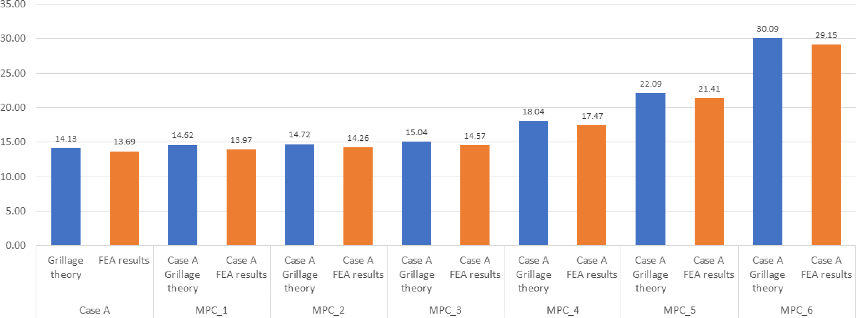
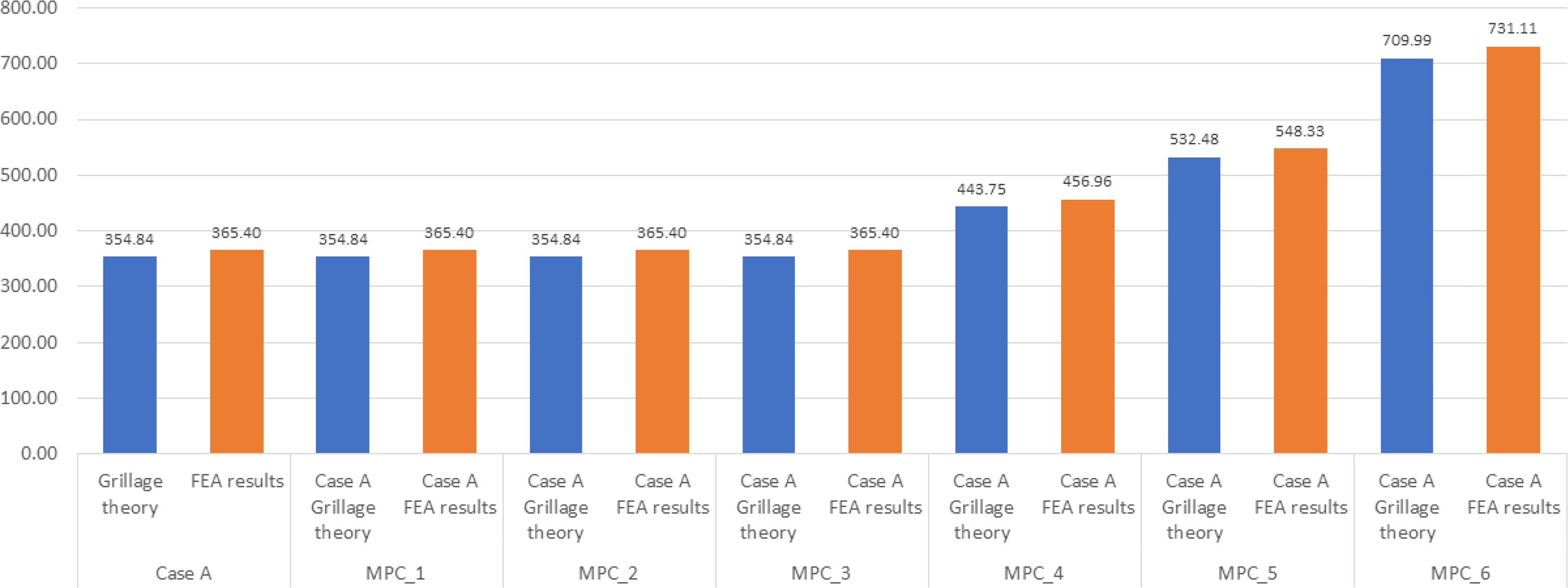
Figs. 7 and 8 compare the maximum deflection and maximum bending stress obtained using the grillage-structure theory and finite-element model for Case A stiffened-plate structure. The maximum deflection shows a 3.3% error and the maximum bending stress shows a 3% error, confirming the accuracy of the developed finite-element model as the above two solutions closely match.
The analysis results for Case B stiffened-plate structure showed a similar trend to the analysis results for Case A stiffened-plate structure. The analysis results, not considering changes in material properties, as well as the analysis results for scenarios MPC_1 to MPC_6 with changes in material properties, revealed that the maximum deflection and maximum bending stress occurred at the central point of the stiffened plate owing to the characteristics of the simple support boundary condition. In results of the analysis not considering changes in material properties, the stiffened plate showed a maximum deflection of 14.19 mm and maximum bending stress of 348.91 MPa under a bending load of 121.7 kPa. In the analysis results for scenarios MPC_1 to MPC_3 applying changes to the material properties of the stiffened plate, a bending load of 121.7 kPa was applied, and all had the same maximum bending stress of 348.9 MPa, but the maximum deflection progressively increased to 14.48 mm, 14.78 mm, and 15.1 mm. For the scenarios MPC_4 to MPC_6, where the allowable stress of DH36 steel material increased by 25%, 50%, and 100% respectively, bending loads of 152.09 kPa, 182.51 kPa, and 243.34 kPa were applied to the stiffened plate; the maximum bending stresses and maximum deflections were 436.03 MPa, 523.23 MPa, and 697.62 MPa, and 18.10 mm, 22.17 mm, and 30.19 mm, respectively.
Figs. 9 and 10 compare the maximum deflection and maximum bending stress obtained for Case B stiffened-plate structure using the grillage-structure theory and finite-element modeling, respectively. The maximum deflection shows an error of 1% and the maximum bending stress shows an error of 1.7%, demonstrating relatively low errors compared to Case A stiffened-plate structure. Therefore, the above two solutions closely match, confirming the accuracy of the developed finite-element model.
5. Conclusions
We conducted a structural response analysis of stiffened-plate structures, a typical hull structure subject to lateral pressure loads, considering changes in material properties of steel used in shipbuilding and marine applications affected by neutron irradiation in the operating environment of nuclear reactors for ships.
In the operating environment of nuclear reactors installed on ships, the material properties of steel exposed to neutron energy change, and we confirmed that the structural responses of stiffened-plate structures in Cases A and B, which consider these changes, differ from those of the identical stiffened-plate structure in ships using conventional fossil fuels. This proves that neutron irradiation affects the steel hull structure of ships and marine applications in terms of strength and stiffness, although there are differences in the extent. The accumulation of neutron irradiation signifies an increase in the changes in the material properties of steel. This was represented by scenarios MPC_1 to MPC_6 in the analysis of this study, considering variations in material properties such as elastic modulus, Poisson's ratio, and allowable stress, based on the experimental and theoretical research on the neutron-irradiated steel.
We analyzed the structural response of the stiffened-plate structure using theoretical grillage-structure theory and analytical finite-element modeling within the static and elastic range. The impact of neutron irradiation on the stiffened-plate structure was determined in terms of load-bearing capacity, strength, and stiffness.
The results of the analysis of the stiffened-plate structure under the same bending load indicated that, as the steel-based stiffened-plate structure got exposed to neutron energy, the maximum deflection proportionally increased, thereby weakening the structural stiffness. For scenarios MPC_4 to MPC_6 with property changes, as the allowable stress of the steel increased, the maximum deflection and the bending load-bearing capacity of the stiffened-plate structure also increased. Therefore, when designing the structures surrounding the hull containment structure where the ship reactor is installed, both strength and stiffness must be considered, and the amount of neutron energy received by the steel is an important consideration.
Ship reactors are typically protected by primary and secondary shielding systems, and the containment structure protects the reactor and serves as a secondary shield. The stiffened-plate structure used as an example in this study was assumed to be located inside the containment structure, thus it was not directly exposed to radiation from the reactor. However, these structures are still in an environment exposed to indirect radiation; therefore, we believe the analysis results for changes in steel properties of stiffened-plate structures under relatively low levels of neutron-irradiation scenarios apply.
The results of this study can be used in the structural design of ships considering the future installation of reactors. Furthermore, the results can be used to formulate the hull design rules from classification societies for ships that adopt nuclear propulsion systems.
A summary of future research plans is as follows. In this study, owing to limited data on the specifications of reactors for ships, the load generated from the weight of the reactor was simply assumed to be the lateral bending load. To supplement this, it is necessary to calculate the specifications for the reactor system and select the target ship to install the reactor, and then carry out structural analysis based on accurate load information calculated therefrom. For the operation of a reactor, a cooling system must be considered. Unlike land-based nuclear power plants, an efficient cooling system must be placed within the confined space of the hull of the ship. Therefore, further structural models must be developed using finite-element modeling for the hull compartment where the reactor and cooling systems are installed, based on the stiffened-plate structures used as examples in this paper. Additionally, structural analysis considering the additional load generated by the cooling system is needed. It is also necessary to understand the effect of neutron irradiation on the welds of the steel structure of the hull. Ships contain a considerable number of welds; these welds sustain the initial residual stress caused by welding, as well as the stress and strain expected during ship operation. Therefore, research on the welds of neutron-irradiated steel is necessary to ensure the structural safety of ships equipped with nuclear reactors.