An Experimental Study of Non-Electrolysis Anti-Microfouling Technology Based on Bioelectric Effect
Article information

Abstract
Biofouling initiated by biofilm (slime) formation is a key challenge for practical ocean engineering and construction. This study evaluated a new anti-biofilm technology using bioelectricity. The anti-microfouling electrical technology is based on the principles of the bioelectric effect, known as the application of an electrostatic force for biofilm removal. Previously, the electricity was optimized below 0.82V to avoid electrolysis, which can prevent the production of biocides. A test boat comprised of microelectronics for electrical signal generation with electrodes for an anti-biofouling effect was developed. The tests were conducted in the West Sea of Korea (Wangsan Marina, Incheon) for three weeks. The surface biofouling was quantified. A significant reduction of fouling was observed under the bioelectric effect conditions, with approximately 30% enhanced prevention of fouling progress (P<0.05). This technology can be an alternative eco-friendly technique for anti-microfouling that can be applied for canals, vessels, and coastal infrastructure because it does not induce electrolysis.
1. Introduction
The ocean covers 70% of the Earth’s surface, with approximately two billion vessels worldwide (Czermański et al., 2022). Marine organisms in the ocean occupy approximately 70% of total biomass (Bar-On et al., 2018). The organisms are viruses, bacteria, archaea, protists, microfungi, and microanimals (Hutchins, 2017). In nature, these organisms attach, grow, and proliferate on the surface or host (Palmer et al., 2007). Once they reach specific populations, they communicate to produce an extracellular matrix to protect them from external stimuli. Biofilms (Flemming and Wuertz, 2019) of multispecies of microorganisms accumulate on any surface, either hydrophilic or hydrophobic, and are established within two weeks. Thus, two billion vessels have biofilms on the surface and travel worldwide. The biofilms on the vessel increase fluidic friction, resulting in a reduction of fuel efficiency that contributes to the greenhouse effect on the earth (Cámara et al., 2022). Therefore, the effective management of biofilms is critical.
Biofilms are the initiative layer for biofouling (Beech, 2004). Various organisms, such as Algae, plants, and small animals (barnacles), attach to the biofilm and build their structure, which usually takes one or two months, depending on the environmental conditions (temperature, salt, and flow velocity). Once biofouling occurs, it requires significant physical brushing and often strong chemical treatments for cleaning (Yebra et al., 2004). The anti-biofouling market is 110 billion USD, including the reduced fuel efficiency caused by biofouling (Isla et al., 2012). Furthermore, biofouling has a global economic impact, including 23 billion USD for antifouling marine coatings to reduce the density and weight of biofilms. The marine environment also transfers invasive species worldwide, leading to significant socioeconomic impacts on fisheries, mariculture, and coastal infrastructure (Molnar et al., 2008); the estimated cost is 4–8 billion USD annually (Fitridge et al., 2012).
Current anti-microfouling technology is focused on surface engineering (Yang et al., 2011), including developing materials for surface coating and high electric current technologies based on the electrolysis of microorganisms (Xue et al., 2015). Developing a biosafe anti-microfouling technology is required because the painting material and induction of electrolysis can generate toxic biocides (Amara et al., 2018). Ultrasound and microbubble-generating technology have also been applied (Park et al., 2017). On the other hand, the technology has limitations in preventing microfouling and generating acoustic noise for marine operations. In general, developing a new solution for antifouling is an urgent challenge for industry and academia.
Our group has been dedicated to preventing biofilms for anti-microfouling processes instead of cleaning approaches. An electrostatic force, the Van der Waals force, was used for biofilm inhibition based on the principles of the bioelectric effect (BE) (Freebairn et al., 2013).
An external electric force can interrupt the biofilms and attached surfaces because biofilms are soluble and electrically charged materials.
This study examined the bioelectric effect in previous work and showed that a specific signal frequency is effective in biofilm treatment (Kim et al., 2015; Subramanian et al., 2020). This technology uses non-electrolysis-induced electrical power, preventing toxic biocides production. The proposed strategy is focused on preventing biofilm formation to control bulk biofouling (Fig. 1).
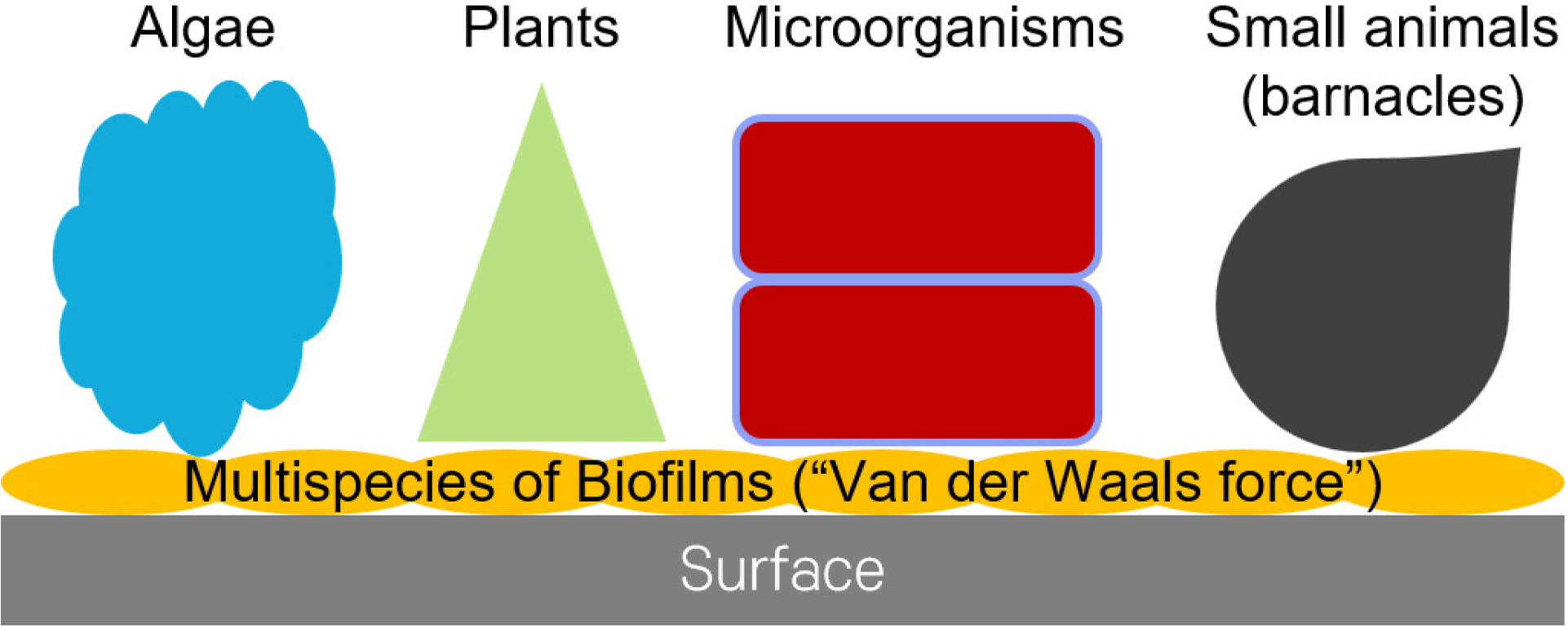
Schematic diagram of biofouling, (1) attached multispecies of biofilms on surfaces (Van der Waals force), (2) marine organisms attached on the biofilms. We are focused on the inhibition of the biofilm layer.
This study focused on demonstrating the electrical technology in real ocean conditions, which are not the same as the standard bacterial growth media, including the concentration of salt and composition of microorganisms. This study developed a non-electrolysis-induced electrical anti-microfouling system. A testing boat comprised of floating parts, electronics, and biofouling monitoring was fabricated. During the test in the West Sea of Korea (Wangsan Marina, Incheon, Korea) for three weeks, the bulk biofouling was monitored using a smartphone, and the surface coverage was quantified using standard software. The results revealed the significant prevention of biofouling.
2. Materials and Methods
2.1 Principles of Biofilm Inhibition (Bioelectric Effect)
An external electric force can inhibit the surface attachment of biofilms through the principle known as the “bioelectric effect” (BE). An alternating current can increase the permeability of the biofilms, resulting in a weak structure susceptible to external stimuli (Kim et al. 2016), and a direct current provides a static force that results in detachment (Del Pozo et al., 2008). The present system utilized an alternative and direct current to maximize the biofilm prevention efficacy. Based on previous work, it is characterized by a 0.7V amplitude of a sinusoidal signal at 10 MHz with a 0.7V offset voltage (Kim et al., 2015; Huiszoon et al. 2019) (Table 1). This signal does not induce electrolysis (Kim et al., 2015).
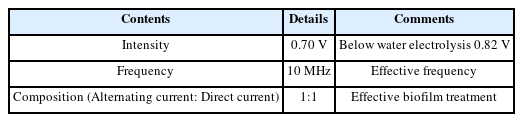
Details of the bioelectric effect
2.2 Electrical System for Testing Setup
Electrical signal generation was realized using a crystal oscillator with a microelectronic circuit design. The performance of the circuit was confirmed by electrical measurements (Fig. 2). Applications of the technology require electrode patterning on the surface. The electrode was fabricated through a traditional flexible printed circuit board (FPCB). The electrode was made of stainless steel to ensure anticorrosive properties. The distance and pitch between the electrodes were the same as in previous work (Kim et al., 2022). Table 2 provides details of the design and materials. The testing conditions were repeated on three plates at the same time. The BE was applied to the three plates for the entire testing period to investigate the efficacy of microfouling prevention. For comparison, an additional three plates have been installed in the boat without applying BE.
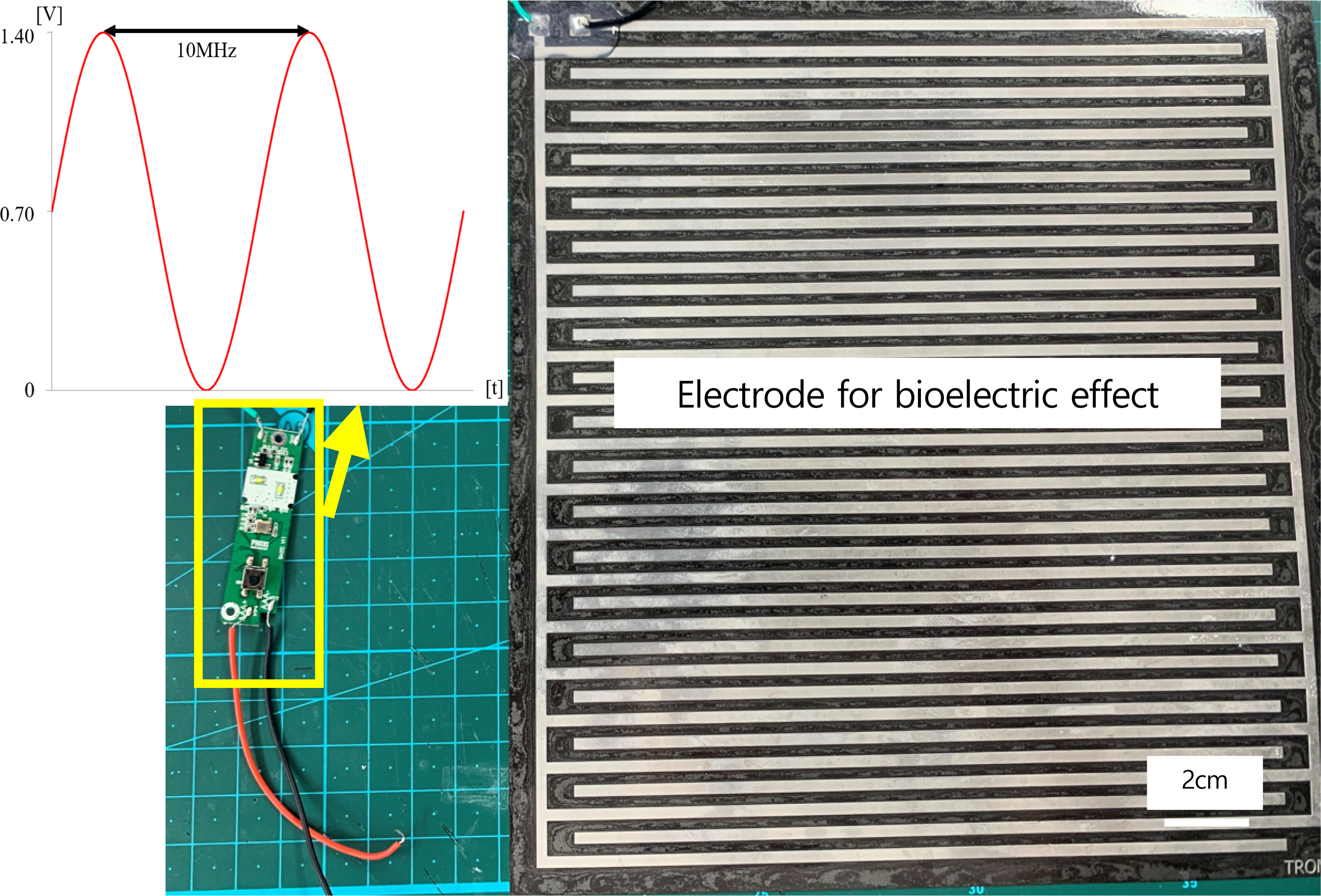
Photo of the electric circuit and electrode for electric signal applications
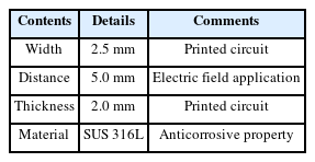
Details of the electrode design
2.3 Fabrication of Testing Boat
Bulk biofouling initiates approximately within three weeks. A testing boat comprised of three major parts was designed and fabricated: (1) floating, (2) electrical system, and (3) biofouling monitoring parts. The floating part was a commercially available tube (maximum 20 kg weight); two tubes were installed in parallel. The electrical system is for a constant supply of the bioelectric effect during testing with a waterproof package. Finally, the biofouling monitoring part was designed to disassemble easily for a visual inspection (Fig. 3). The boat was placed in the West Sea of Korea, Incheon, from May 19th to June 9th, 2022. Considering the progress period of microfouling (Gizer et al. 2023), the surface was inspected at initial (day “0”), 8 d (day “8”), and 20 d (day “20”) later.
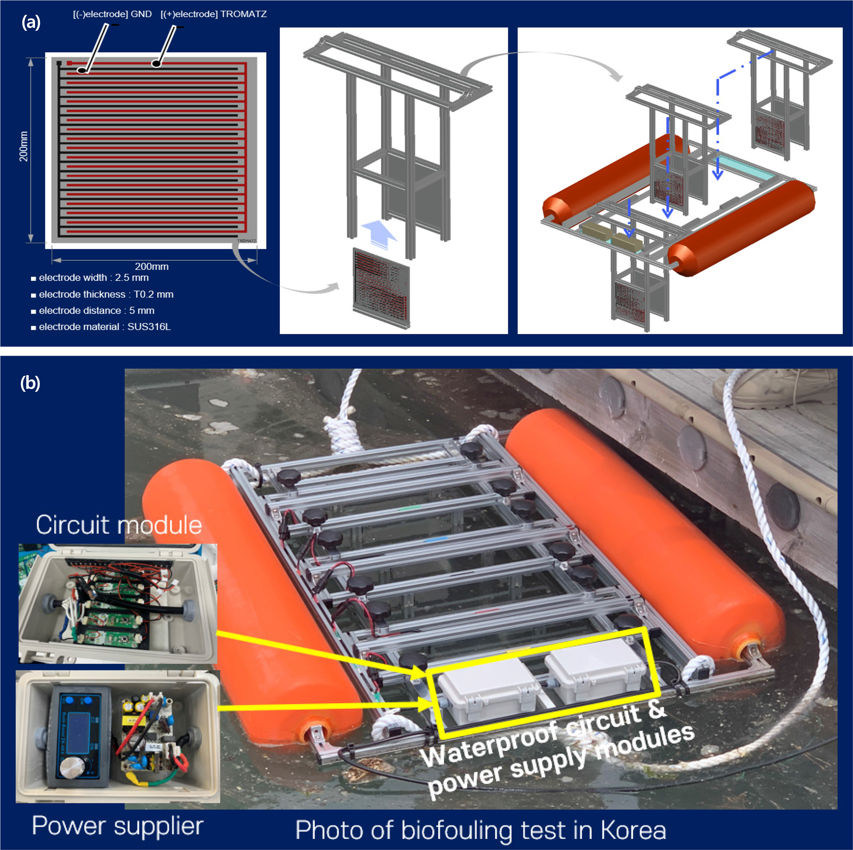
Details of the testing boat: (a) Schematic of biofouling monitoring part; (b) photo of the testing boat and electrical system
2.4 Data Analysis
Surface coverage analysis, especially on microfouling, was performed as a rapid quantification method in ocean research (First et al., 2021). The testing period (three weeks) focused on the prevention of microfouling. The image was taken using a smartphone camera (Samsung Galaxy S22). The surface biofouling coverage was quantified by Image J 1.53 (NIH, USA) using binary image analysis.
The statistical analysis was performed using the analysis of variance (ANOVA): p-value analysis first and followed by post-hoc testing, which is a standard statistical tool for group data analysis (Bailey et al., 2008). ANOVA was performed on the bioelectric effect “ON” and “OFF” groups from the initial 8- and 20-day data groups. The statistical significance between the technology “ON” and “OFF” groups at each examination period was critical because this study focused on the technology validation.
3. Results
The results were collected three times during the experiments. A photograph of the biofouling monitoring part is summarized in Figs. 4–6. After eight days, biofouling was not significant in the bioelectric effect “ON” and “OFF” conditions, as shown by the clear electrode pattern. On the other hand, intensive biofouling was observed under the bioelectric effect “OFF,” in which biomass covered the electrode pattern. When the bioelectric effect was applied, the image showed a significant reduction of biomass formation on the electrode (bioelectric effect “ON”). Thus, applying the bioelectric effect can prevent biofouling on the surface.

Images of the biofouling part (Days 0, 8, and 20)
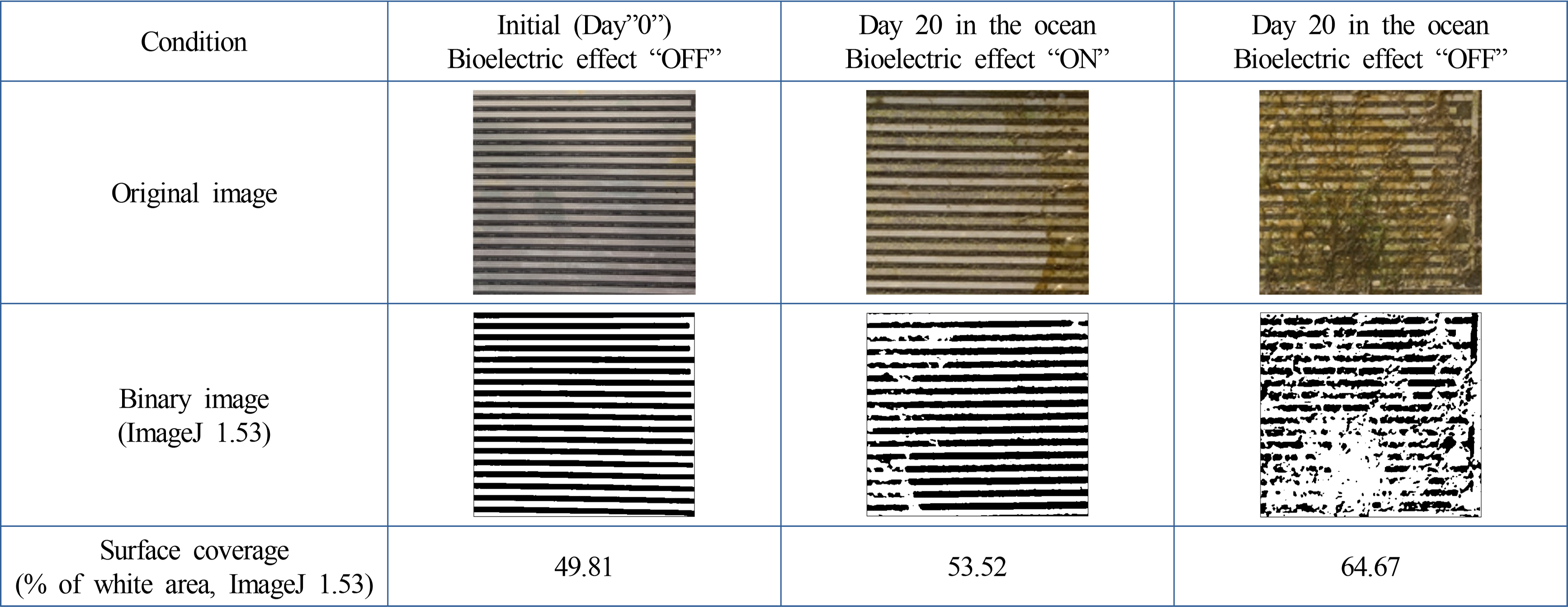
Binary image conversion (Representative images)
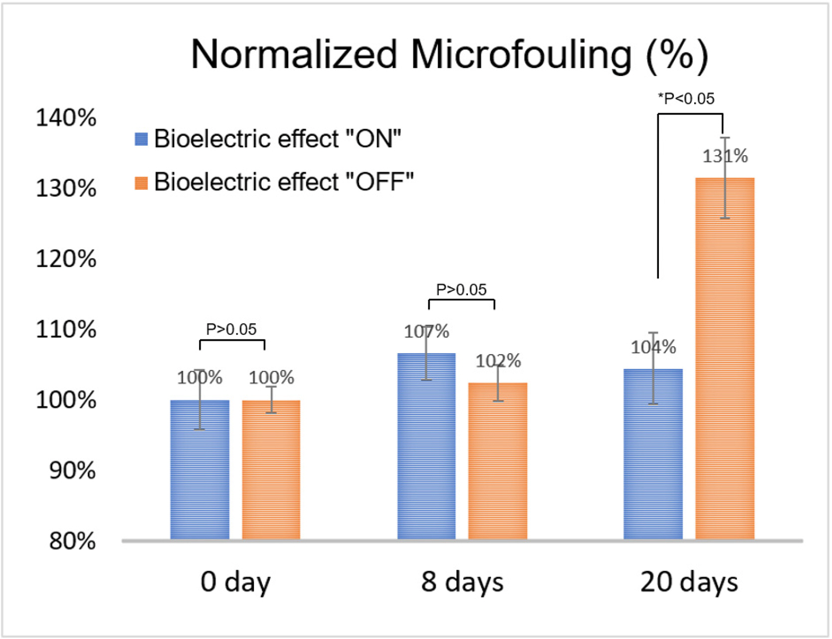
Normalized microfouling in the bioelectric effect “ON” and “OFF”
Quantitative analysis of the images was performed using the standard image process software (ImageJ 1.53., NIH, USA) (Kim et al., 2015; Kim et al., 2016). The image focused on the surface coverage of the electrode (bright area compared to the dark background). The photograph was loaded on the ImageJ program and converted binary (black and white), as shown in Fig. 5. The surface coverage was quantified, focusing on the area of the black respected to the entire area. Table 3 lists the surface coverage data (binary option: iteration 1, count 1). The initial data was approximately 50% surface coverage because of the electrode portion (Fig. 5). Compared to the initial stage, the biofouling process was analyzed by normalizing the surface coverage (Table 3). The quantitative data also showed significant prevention of microfouling when the bioelectric effect was applied (p < 0.05, ANOVA). Therefore, the bioelectric application demonstrates the effective prevention of biofouling.

4. Discussion
Some local biofouling progress was observed when the bioelectric effect was applied, as shown in Figs. 4–6. In this study, the intensity of the field can be varied, especially on the corner of the electrode, because the electric field is not uniform in the biofouling monitoring part. The electric charge density of the rectangular shape is higher than the parallel electrode (Itoh and Itho, 1996). The following variables were examined to optimize the spatial electric field distribution: (1) electrode rounding at the corner, (2) electrode density (surface coverage), (3) electrode width, and (4) electrode pattern (rectangular and circular). Although this study was not optimized in electric field distribution, the results showed a significant decrease in the biofouling progress.
The bioelectric effect is based on applying an electrostatic force, Van der Waals force. Biofilms are attached to the surface using the Van der Waals force (Garrett et al., 2008). Therefore, when the same force mechanism is applied, it can induce the detachment of the biofilms. The typical thickness of biofilms is 100 μm (Kim et al. 2012) and comprises more than 700 species of bacteria and microorganisms (Clarke, 2016). Owing to the heterogeneous composition of biofilms, the electric field or force effect is considered a general method for various biofilm treatment applications, including clinical infections (Ehrlich et al., 2005) and environmental contamination management (Hu et al., 2022). For ocean applications, its efficacy will be examined further under various ocean conditions, including the changes of salt in seawater with temperature.
The bioelectric effect applied in this study was characterized as non-electrolysis-induced technology because the effective electric voltage was below 0.82V (Kim et al., 2015). This is critical, especially considering eco-friendly technology development for ocean engineering. The electrolysis creates biocidal radicals and by-products, which can be toxic to humans and marine organisms. Therefore, this technology can contribute to developing an alternative eco-friendly anti-microfouling technology for vessel and ocean engineering structure applications.
The future implementation of the technology on the vessel will require overcoming some expected challenges. First, the electrode should be patterned on the vessel surface, which is required to develop a new electrically conductive material paint to provide a bioelectric effect. The reliability of the conductive paint is critical as the vessel lifetime is expected to be over thirty years. For effective operation, a real-time monitoring system of the anti-microfouling is also required. This study is currently working on optimizing the bioelectric effect for the anti-microfouling process and designing the real-time detection of biofouling based on previous work (Kim et al., 2012). In particular, a conductive painting process will be developed to provide the microcurrent on the niche area of the vessel where surface cleaning is challenged. The electronics part is developing further with a combination of deep-learning algorithms to minimize the antifouling efficacy on various vessels and coastal infrastructures.
5. Conclusions
This paper reported a non-electrolysis-induced anti-microfouling technology that prevents biofilm formation in the ocean. The principles of biofilm prevention are known as the bioelectric effect, which uses the electric force (Van der Waals) for surface detachment. A testing system was developed, and an investigation was performed for three weeks in the West Sea of Korea. The results show that the bioelectric effect significantly inhibits biofouling, with approximately 30% more reduction than under the non-bioelectric effect. This technology can be an appropriate method for eco-friendly biofouling management owing to non-electrolysis induction. Bioelectric effect technology will be developed further for vessel and ocean engineering applications.
Notes
The authors declare no conflict of interest.
This research was supported by the Korea Institute of Marine Science & Technology Promotion (KIMST), funded by the Ministry of Oceans and Fisheries (2021050012).
Acknowledgements
Author thank the College of Medicine, University of Ulsan, for the technical support.