1. Introduction
The manoeuvring performance of merchant ships is estimated starting in the design stage through empirical equations using the principal dimensions of the ship, hydrodynamic derivatives obtained from a captive model test conducted using a model ship, a virtual captive model test using computational fluid dynamics (CFD), and mathematical modeling of the manoeuvring of the ship. For fishing vessels, on the other hand, most studies target constructed fishing vessels and estimate their manoeuvring performance through a comparison between a buoy bearing method using a real ship and differential global positioning system, an analysis of turning circle changes according to rudder angle and ship speed, and a zig-zag test. Research on estimating and evaluating manoeuvring performance in the design stage is scarce (Lee et al., 2018).
A study conducted on the manoeuvring performance characteristics of fishing vessels (Lee et al., 2018) used empirical equations and analyzed the effects of empirical equations on the estimation of the manoeuvring performance of fishing vessels. The authors used empirical equations considering stern shape and not considering stern shape in a turning movement simulation, and verified whether the manoeuvring performance standards of the International Maritime Organization (IMO) were satisfied. They further compared the results with the turning movements of a real ship. Their results showed that the IMO manoeuvring performance standards were satisfied, but a significant difference with the turning movement results of the real ship was found. The reason is attributable to the fact that the manoeuvring performance of fishing vessels was assessed based on the empirical equations of merchant ships; it was thus deduced that the parameters to estimate the manoeuvring performance of fishing vessels considering their shapes and motion characteristics arerequired. Kim et al. (2020) also performed a simulation on the turning movements of fishing vessels utilizing empirical equations consisting of the characteristics of hull shape parameters of fishing vessels. The simulation results showed a substantial error in turning movement estimation due to a difference in hull forms between merchant and fishing vessels. These results implied the necessity of empirical equations considering hull forms of fishing vessels to improve the estimation accuracy of turning performance.
In a study related to the rudder of fishing vessels, Kim et al. (2022) investigated the design practice of a rudder area for which assessment criteria and design standards were not clearly established among 153 fishing vessels operating in Korea, and statistically confirmed that the majority of fishing vessels were designed with a rudder area which does not satisfy international standards. Park et al. (2013) performed sea trials of fishing vessels equipped with a fiber-reinforced plastic (FRP) rudder and a square-shaped metal rudder, and verified that the FRP rudder outperformed the square-shaped metal rudder in turning when the rudder area was identical.
As explained above, the manoeuvring performance and rudder of fishing vessels have been investigated; however, insufficient efforts have been made on estimating hydrodynamic derivatives considering the hull form of fishing vessels in the design stage or assessing manoeuvring performance using a manoeuvring motion model. Furthermore, fishing vessels have large hydrodynamic nonlinearity depending on the changes in the submerged hull body and significant differences in hull forms according to fishing methods. Since there is a limitation in assessing manoeuvring performance by creating a manoeuvring motion mathematical model of the mathematical modeling group type, the manoeuvring performance of fishing vessels needs to be more directly assessed using a CFD simulation based on Reynolds averaged Navier-Stokes (RANS) equations. A proper rudder needs to be designed for fishing vessels since their veering and turning performance is particularly important considering their operation characteristics; however, there is insufficient data on principal dimensions and rudders for small fishing ships and on the correlation between the fishing ship and rudder. Therefore, a proper rudder design for small fishing ships must be devised by evaluating the changes in manoeuvring performance according to the rudder cross-section changes in the rudder area of fishing vessels.
This study directly assessed the manoeuvring performance of small fishing ships having various bow hull shapes using a RANS-based CFD simulation. A variety of rudder shapes were applied to fishing vessels to perform turning and zig-zag simulations, and rudder design measures were proposed considering changes in manoeuvring performance according to the rudder cross-section and area.
2. Manoeuvring Performance Assessment According to Hull Form
2.1 Target Vessel
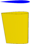
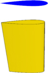
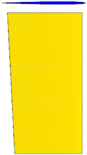
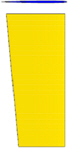
The target vessel analyzed in this study was a 4.99-ton coastal fishing vessel in which three different types of bow hull–one chine original, bulbous bow, and spoon bow–were used as shown in Fig. 1. A model ship with the 1:11 ratio was used in the simulation, and the principal dimensions are presented in Table 1. The presented specifications are as follows. Lpp is the length, B is the width, D is the depth, T is the draft, Fn is the Froude number, A is the lateral area of the hull submerged below the waterline of the fishing vessel without a rudder, which was measured using a commercial CAD program. The lateral area of the submerged hull is shown in yellow lines in Fig. 2.
2.3 CFD Model Verification: Resistance Simulation
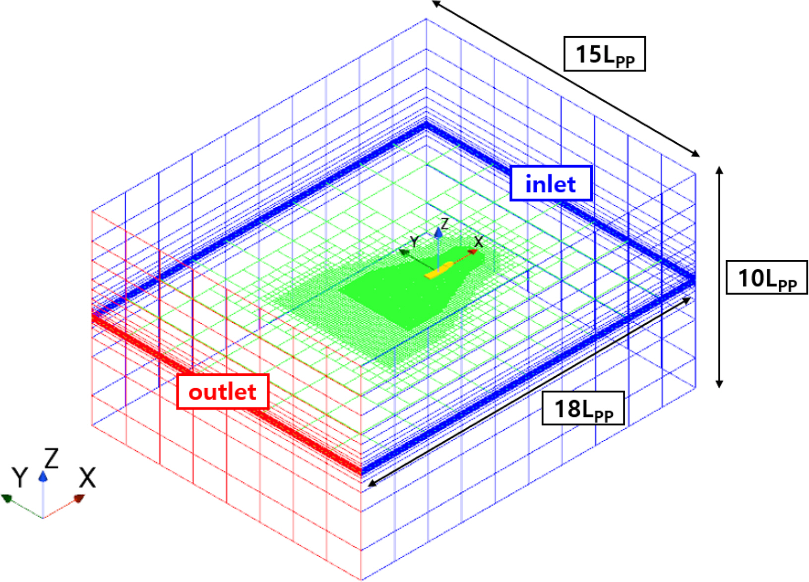
Before performing the free-running simulation in calm water, a resistance simulation was performed for verifying the CFD model of the target vessel in this study. The computational domain for the simulation is shown in Fig. 3. The computational domain was set to satisfy the recommended procedures and guidelines of the International Towing Tank Conference (ITTC) (ITTC Resistance Committee, 2017). The length from the center of the vessel to the bow is 5.5 Lpp, 12.5 Lpp toward the stern, 7.5 Lpp toward the port side and the starboard side, and 5.0 Lpp toward the bottom and the deck each the boundary conditions of each boundary in the computational domain are shown in Table 3.
For the simulation, commercial CFD software STAR-CCM+(16.06 ver) was used. To create a mesh, the trimmed mesh and prism layer features of STAR-CCM+ were used. The mesh density was set differently using the trimmed mesh feature depending on the flow characteristics. A boundary layer mesh was used around the hull and on the surface to ensure that the flow at the boundary layer was accurately calculated. Furthermore, the dynamic fluid body interaction feature was used to consider the changes in the position of the hull, and an overset mesh was used to discretize the entire computational domain on the hull movement. The volume of fluid feature was used to consider multiphase flows to implement the free surface.
In Table 4, The total resistance of a ship is nondimensionalized and described using the CTM, and it can be calculated through Eq. (1). In Eq. (1)v, ρ, and Aw represent the design speed of the ship, water density, and the wetted surface area of the ship, respectively.
As shown in Table 4, the resistance simulation result demonstrated that resistance decreased in the order of one chine original, spoon bow, and bulbous bow, and the resistance performance of the bulbous bow was most outstanding.
2.4 Turning Simulation According to Hull Form
A starboard +35° turning simulation was performed to evaluate the turning performance according to hull forms. The turning trajectory, which is the simulation result, is illustrated as a dimensionless value in Fig. 7; the comparison of advanced length and tactical diameter of each hull form is presented in Table 5. The turning radius according to the hull form increased in the order of one chine original, bulbous bow, and spoon bow. The turning performance was compared between the hull forms with respect to the tactical diameter and advance length, which are the turning performance indicators. The one chine original form exhibited the most outstanding turning performance. Because the resistance performance of the one chine original form was the least outstanding, the relatively larger thrust and wake fraction of the propeller compared to other hull forms increased the direct compressive force of the rudder resulting in excellent turning performance.
2.5 Zig-zag Simulation According to Hull Form
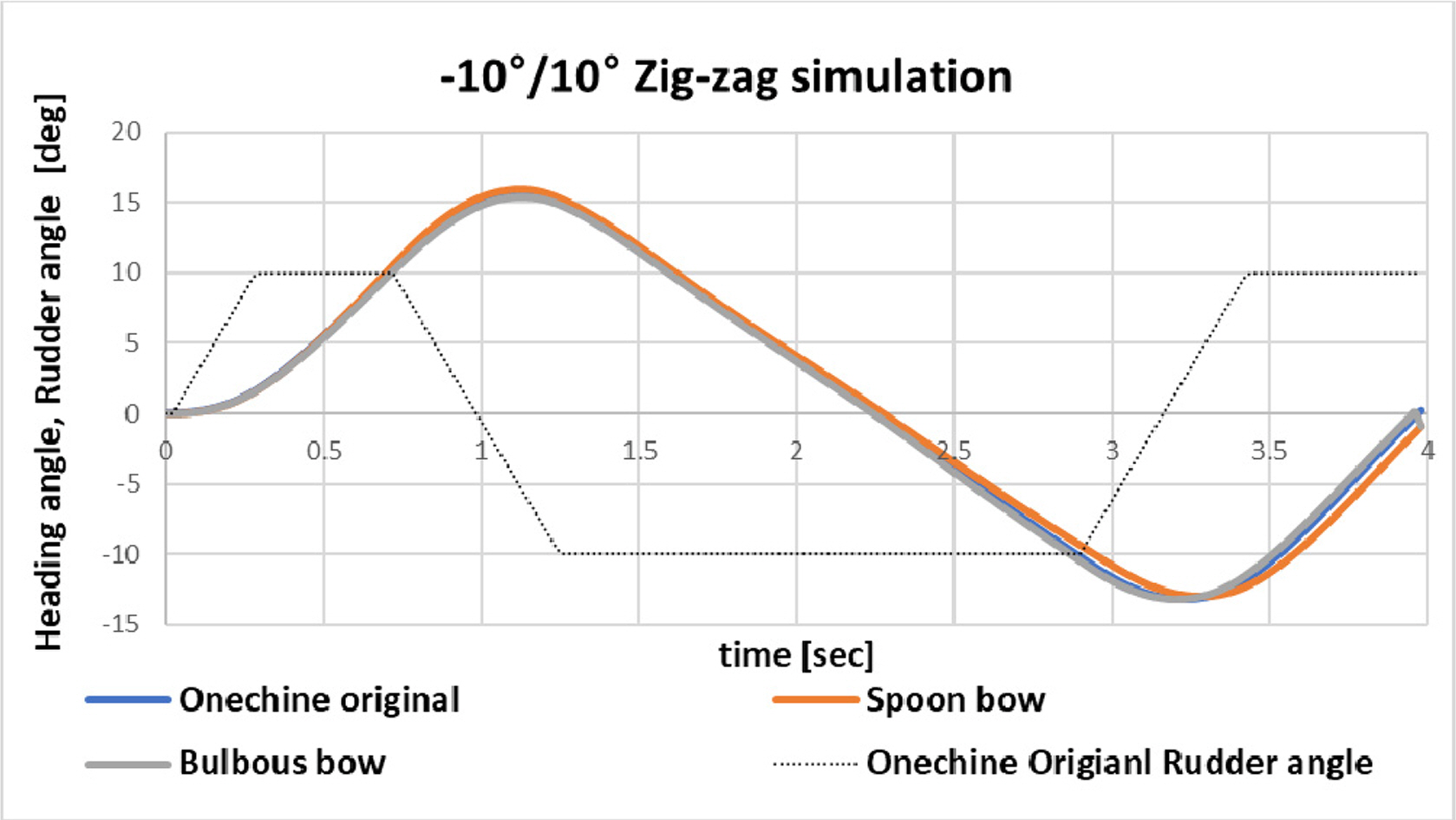
A −10°/10° zig-zag simulation was performed to evaluate the veering performance according to hull forms. The simulation results are summarized in Fig. 8 and Table 6; only a minor difference in the veering performance was found between the three hull forms of one chine original, bulbous bow, and spoon bow. The 1st overshoot angle, which is the veering performance indicator, decreased in the order of the bulbous bow, one chine original, and spoon bow, and all three hull forms satisfied the IMO standard, which implies that the target vessel has adequate veering performance and course stability performance as a fishing vessel.
3. Modeling of Rudder Shape Having Various Cross-Sections and Aspect Ratios
3.1 Rudder Shape Modeling by Applying NACA Cross-Section
The cross-section was varied to model five rudder shapes to evaluate the manoeuvring performance with respect to the rudder cross-section. The National Advisory Committee for Aeronautics (NACA) airfoil cross-section was applied to increase the lateral force applied to the rudder. For the comparison with a plate rudder which was previously used in the manoeuvring performance simulation evaluation according to hull form, the thickness of the rudder cross-section was varied with respect to NACA0006 having the same maximum thickness as the plate rudder in which the rudder shape was modeled using five cross-sections: NACA0003, NACA0006, NACA0010, NACA0012, and NACA0025. The respective results are shown in Table 7.
3.2 Comparison of Lateral Force on the Rudder According to Rudder Cross-Sectional Shape
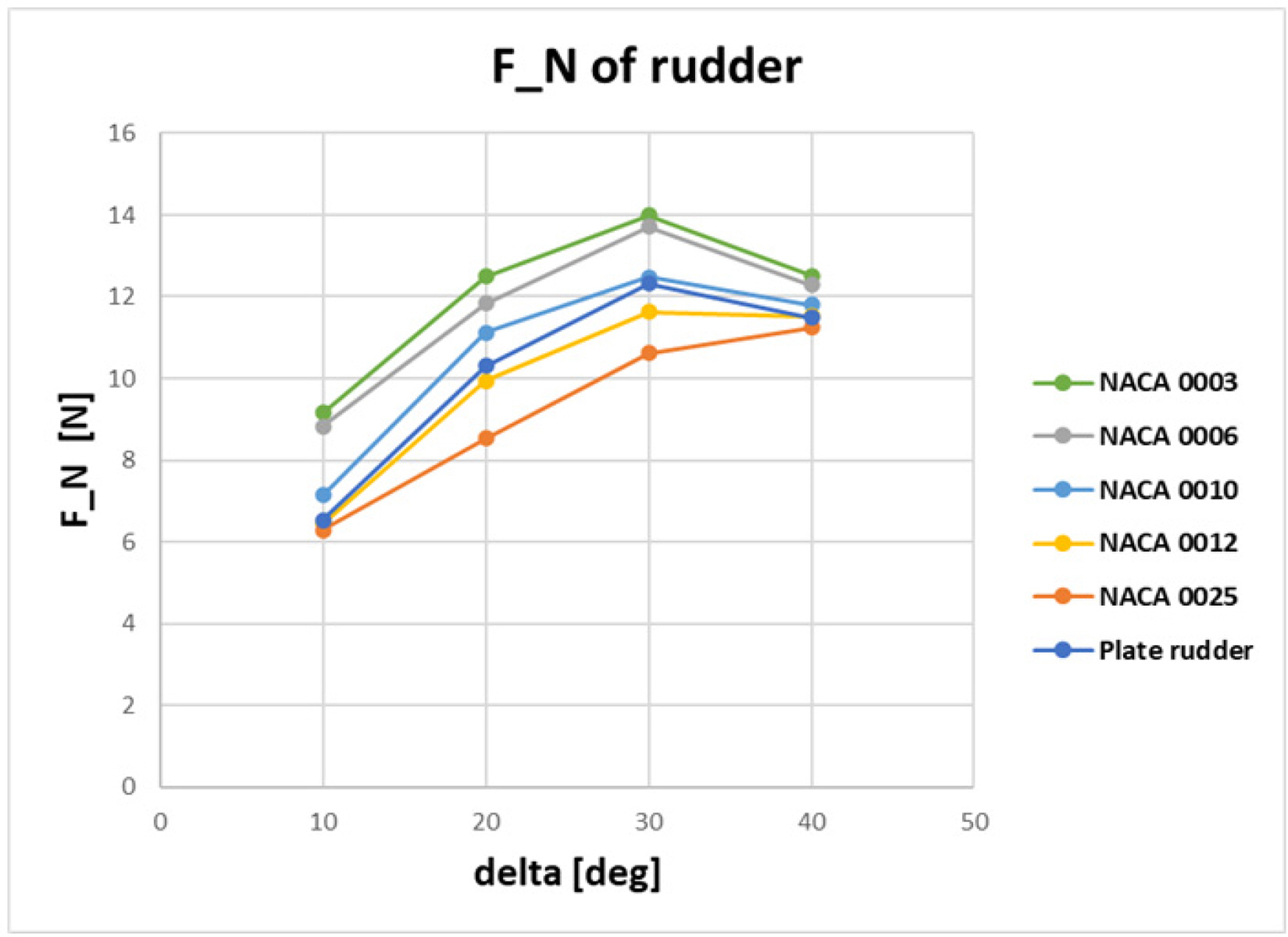
For comparing the performance between the rudder modeled in Section 3.1 and the plate rudder, the lateral force acting on the rudder was calculated by changing the steering angle from 10° to 40° at the increment of 10°. The lateral forces on the rudder having NACA cross-section and the plate rudder are shown in Fig. 9. The maximum lateral force occurred at 30° in all rudders, and the lateral force decreased beyond 30° due to the occurrence of the stall. Additionally, the NACA0006 rudder having the same thickness as the plate rudder 0006 receives a greater lateral force than the plate rudder, thus being more advantageous in terms of improving the manoeuvring performance of fishing vessels.
3.3 Modeling of Rudder Shapes Having Various Aspect Ratios
From the calculated lateral force applied to the plate rudder and five rudders having NACA cross-sections, rudder shape modeling was performed by changing the rudder area of the NACA0003 rudder, which had the highest lateral force. Based on 6.5% aspect ratio (AR/A) of the lateral area of the submerged hull to the rudder area of the plate rudder, the aspect ratio of five rudder shapes was varied by 4.5%, 5.5%, 6.5%, 7.5%, and 8.5% to model the rudder shape. The constraint of rudder span caused by the stern shape was taken into consideration in the rudder modeling, and a larger aspect ratio was assigned to the same rudder area considering the lift characteristics. The shape and specifications of the modeled rudders are shown in Table 8.
4. Manoeuvring Performance Assessment According to Rudder Aspect Ratio
4.1 Zig-zag Simulation Results According to Rudder Aspect Ratio
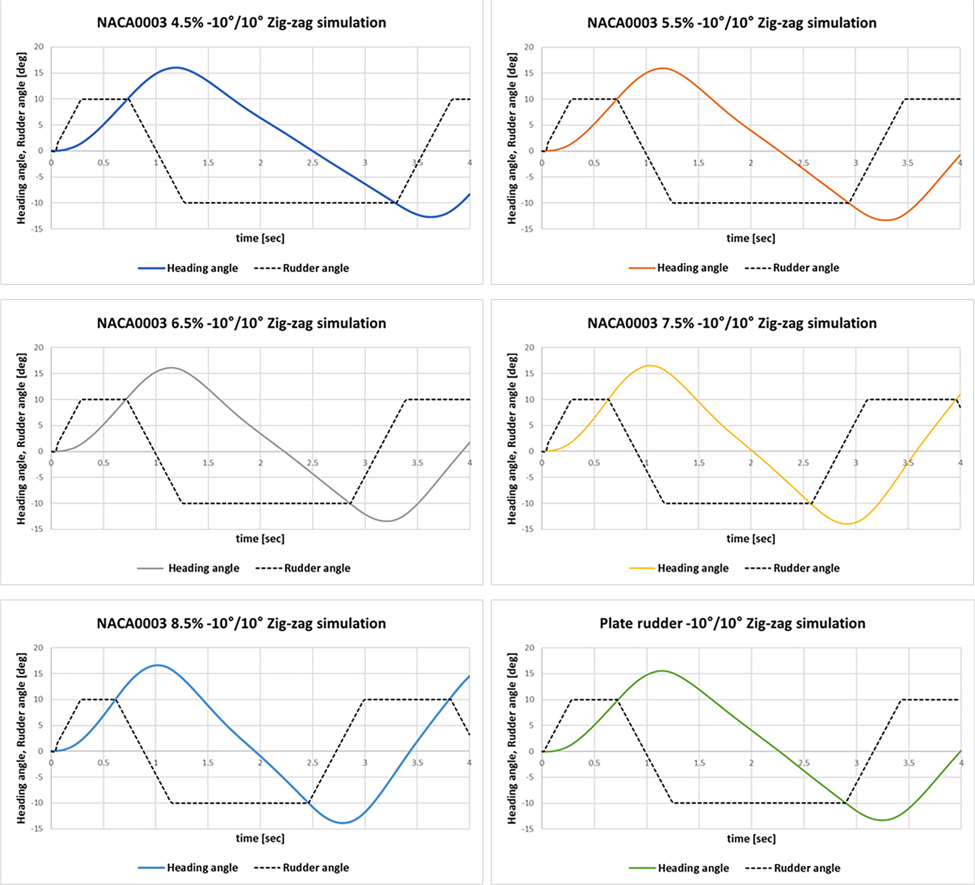
To assess the veering performance of rudders having various aspect ratios as modeled in Section 3.3, a −10°/10° zig-zag simulation was performed for the one chine original form, which demonstrated the best manoeuvring performance; the relevant results are illustrated in Fig. 10 and Table 9. As shown in the results of the zig-zag simulation, the overshoot angle increased as the rudder aspect ratio increased. However, IMO manoeuvring performance standards for vessels of Lpp 100 m or above were satisfied in all rudder aspect ratios. Therefore, sufficient veering performance and course stability were expected when the NACA003 cross-sectional rudder, having five aspect ratios modeled in this study, was applied to the target fishing vessel.
4.2 Turning Simulation Results According to Rudder Aspect Ratio
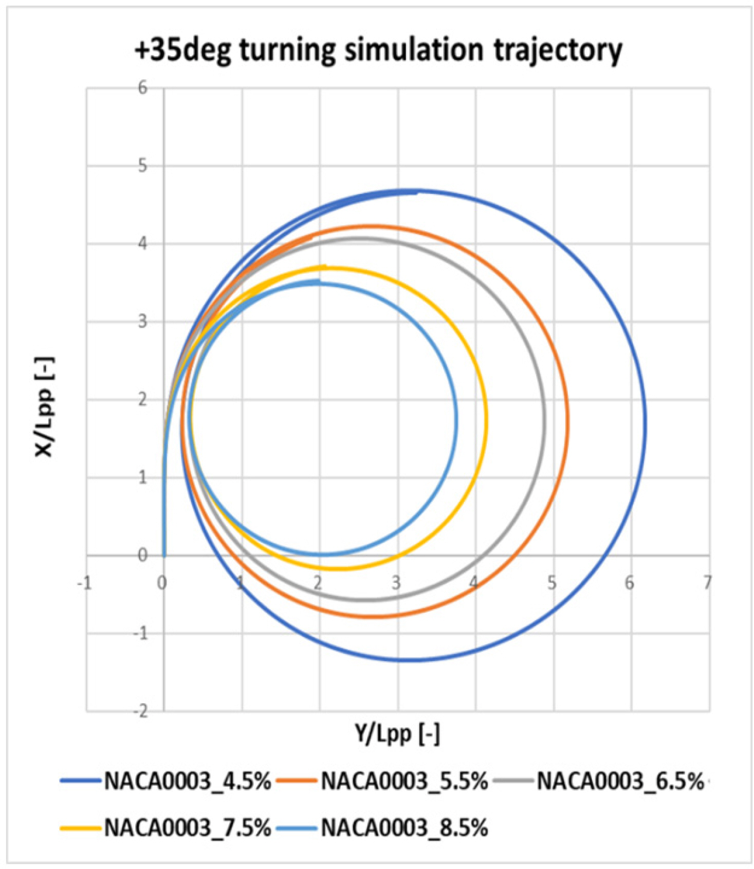
To assess the turning performance of rudders having various aspect ratios as modeled in Section 3.3, a +35° turning simulation was performed for the one chine original form, which demonstrated the best manoeuvring performance. The turning trajectory, which is the simulation result, is illustrated as a dimensionless value in Fig. 11; the tactical diameter and advance length are summarized in Table 10. As shown in the turning simulation results, both tactical diameter and advance length decreased as the rudder aspect ratio increased, in which NACA0003 6.5%, 7.5%, and 8.5% rudders all satisfied the IMO manoeuvrability standard requirements. NACA0003 4.5% and NACA003 5.5% rudders did not satisfy the IMO manoeuvrability standard requirements; however, the IMO standard targets vessels of Lpp 100m or above. Therefore, the target vessel is deemed to have sufficient turning performance considering that it is a small fishing ship with a small Lpp.
As shown in Table 10, the tactical diameter decreased by 16.78% and 14.84% when the rudder aspect ratio increased from 6.5% to 7.5% and from 4.5% to 5.5%, respectively. However, the aspect ratio decreased from 2.3 to 2.0 owing to the constraint of the stern shape when the aspect ratio was 7.5%. This is disadvantageous from the perspective of rudder lift characteristics and resistance performance of fishing vessels. Thus, the most efficient change in the aspect ratio for the target vessel is an increase from 4.5% to 5.5% in terms of manoeuvring performance.
5. Conclusion
This study assessed the manoeuvring performance of a small fishing vessel having various hull forms using a CFD simulation, aiming the propose the design direction for the rudder shape of fishing vessels by considering the changes in the manoeuvring performance according to cross-sectional shape and area of rudders. The following conclusions were drawn.
First, turning and zig-zag simulations were carried out using CFD to assess the manoeuvring performance of fishing vessels. Without the use of empirical equations or an MMG manoeuvring motion model, the effectiveness of directly assessing the manoeuvring performance of fishing vessels using a RANS-based CFD simulation was verified.
Second, turning and zig-zag simulations were performed for three types of hull forms–one chine original, bulbous bow, and spoon bow – to evaluate manoeuvring performance according to hull form. The simulation results showed that the manoeuvring performance was in the order of one chine original, bulbous bow, and spoon bow. The hull form of the fishing vessel must be determined by comprehensively reviewing the manoeuvring performance as well as resistance and self-propulsion performance.
Third, when the manoeuvring performance was compared according to the changes in rudder cross-sectional shape, the rudders with NACA cross-section outperformed the plate rudder in terms of lateral force and manoeuvring performance, particularly in terms of turning performance. Furthermore, the manoeuvring performance assessment conducted according to rudder shape confirmed that the improvement of manoeuvrability with respect to 1% increase in rudder aspect ratio was the most efficient for the rudder aspect ratio of (AR/A) 5.5%.
Therefore, this study suggests the design of the rudder in fishing vessels employs NACA cross-section and the rudder area to adopt the aspect ratio (AR/A) that reflects the lateral area of the submerged hull. This study also proposes the selection of the rudder aspect ratio that results in the most efficient improvement of the manoeuvring performance with respect to the increase in the rudder area. However, the cross-section and area of the rudder cannot be simply determined based on the lift characteristics and manoeuvring performance; thus, further research is required on rudder shape design of small fishing vessels by comprehensively considering rudder span according to stern shape, constraints of chords, structural stability, and productivity of the rudder.