1. Introduction
Energy consumption is increasing rapidly with population growth and technological development. In particular, the excessive development and use of fossil energy cause a global pollution problem, and excessive greenhouse gas emissions, including carbon dioxide, leads to global warming and various environmental problems. Therefore, it is essential to develop technologies for renewable energy, which is a sustainable and eco-friendly energy source (Muliawan et al., 2013; Ullah et al., 2020).
Among renewable energy sources, offshore wind energy, wave energy, and current energy, which are representative offshore energy sources, require future-oriented and continuous technology development. In particular, many technologies have been developed for offshore wind energy because it has benefits in terms of wind homogeneity and speed as well as the installation location compared to onshore wind energy (land-based wind energy). Large-scale commercial power generation is also possible because it is free of the restrictions of many wind turbine installation spaces and noise (Bae and Kim, 2013). As offshore wind turbine technology has grown into a major energy source worldwide, including in Europe, many studies have been conducted to increase the economic feasibility of offshore wind turbine platforms (Global Wind Energy Council Global, 2019).
A combined wind-wave energy platform in which wave energy converters (WECs) are attached to floating wind turbines has been reported as one way to increase the economic feasibility of floating offshore wind turbine (FOWT) in many studies. The combined energy platform is based on the typical characteristics of ocean environments: relatively high waves accompany high wind speeds. Moreover, using two energy sources makes it possible to reduce the energy extraction variability of a single offshore wind turbine and increase the economic effects (Kim et al., 2015). As a combined wind-wave energy platform type, there is a combined platform model that combines the OC4 model (Robertson et al., 2014), a semi-submersible wind turbine structure disclosed by the National Renewable Energy Lab (NREL) in the United States, with Wavestar-type WECs (Hansen et al., 2013). Si et al. (2021) analyzed the motion performance and power generation efficiency of this platform. A study also proposed a model by combining OC (Jonkman, 2010), a Spar-type wind turbine of NREL, with Wavestar-type WEC and analyzed its motion performance and power generation efficiency (Ghafari et al., 2021). In South Korea, many studies have been conducted, including a study on the conceptual design of a large combined wind-wave energy platform based on a semi-submersible (Kim et al., 2015), a study on the hydrodynamic interaction between a combined energy structure and the attached WECs (Lee et al., 2016), and a study on the design of a motion reduction device for a combined energy platform (Park et al., 2018).
Few studies have examined the performance of combined energy platforms based on a tension-leg platform (TLP), a representative offshore structure with excellent motion performance on waves. TLP is very stable in terms of heave, pitch, and roll compared to a semi-submersible or Spar platform (Oguz et al., 2018), and the platform construction cost is relatively low (Tsouroukdissian et al., 2016). In addition, when a large-scale offshore wind farm is constructed, the installation area of mooring lines is smaller than that of catenary mooring lines because they are installed vertically downward, causing less interference with nearby structures or maritime fishing activities. Therefore, various studies have been conducted worldwide on TLP-type offshore wind turbine platforms (Adam et al., 2014; Kim et al., 2016; Chung et al., 2021; Ren et al., 2022). A previous study reported that the TLP platforms are economical because their life-cycle cost (LCC) is relatively lower than that of Spar plftforms (Pantusa et al., 2020). For TLP platform, however, the natural frequency of the platform motion is high because of the high stiffness of mooring lines. A relatively large motion response occurs under high-frequency wave loads, such as 2nd-order sum-frequency wave loads. This leads to an increase in the fatigue of mooring lines (Kim, 1991). Therefore, it is necessary to identify the motion response characteristics of a combined wind-wave energy platform precisely based on the TLP platform. In particular, understanding the motion characteristics of TLP platform under 2nd-order wave loads provides the basic knowledge required for designing combined energy platforms in the future; it makes it possible to secure the diversity of platforms to be designed.
Therefore, this study analyzed the motion characteristics under 2nd-order wave loads to identify the precise motion response of a combined wind-wave energy platform based on the TLP structure. A platform that combined MIT-NREL TLP (Matha et al., 2010), a TLP-type offshore wind turbine model disclosed by NREL, with Wavestar-type WECs was set as a numerical model. As mentioned above, this is to present a new type of combined wind-wave energy platform to which a movable body-type WEC is attached while utilizing the excellent motion response performance of TLP on waves and the advantages of installing multiple WECs. In particular, the wind load acting on the wind turbine was excluded, and focus was given to the analysis of the motion by the wave load to identify the motion response characteristics of the structure that combined TLP with hemispherical WECs under 2nd-order wave loads. The motion characteristics of the combined platform were compared according to the application of the 2nd-order sum-frequency wave load and the attachment of WECs. The power take-off (PTO) model was applied to WECs.
In this study, ANSYS AQWA (AQWA-NAUT module), a hydrodynamic program, was used to calculate the motion performance of the combined energy platform. In order to apply the 2nd–order wave loads and the nonlinear Froude-Krylov force that changes every time step due to body motion to the platform and apply the PTO damping force to the WECs, a user-subroutine was developed and numerical analysis was performed in connection with the AQWA program.
2. Numerical Analysis Model
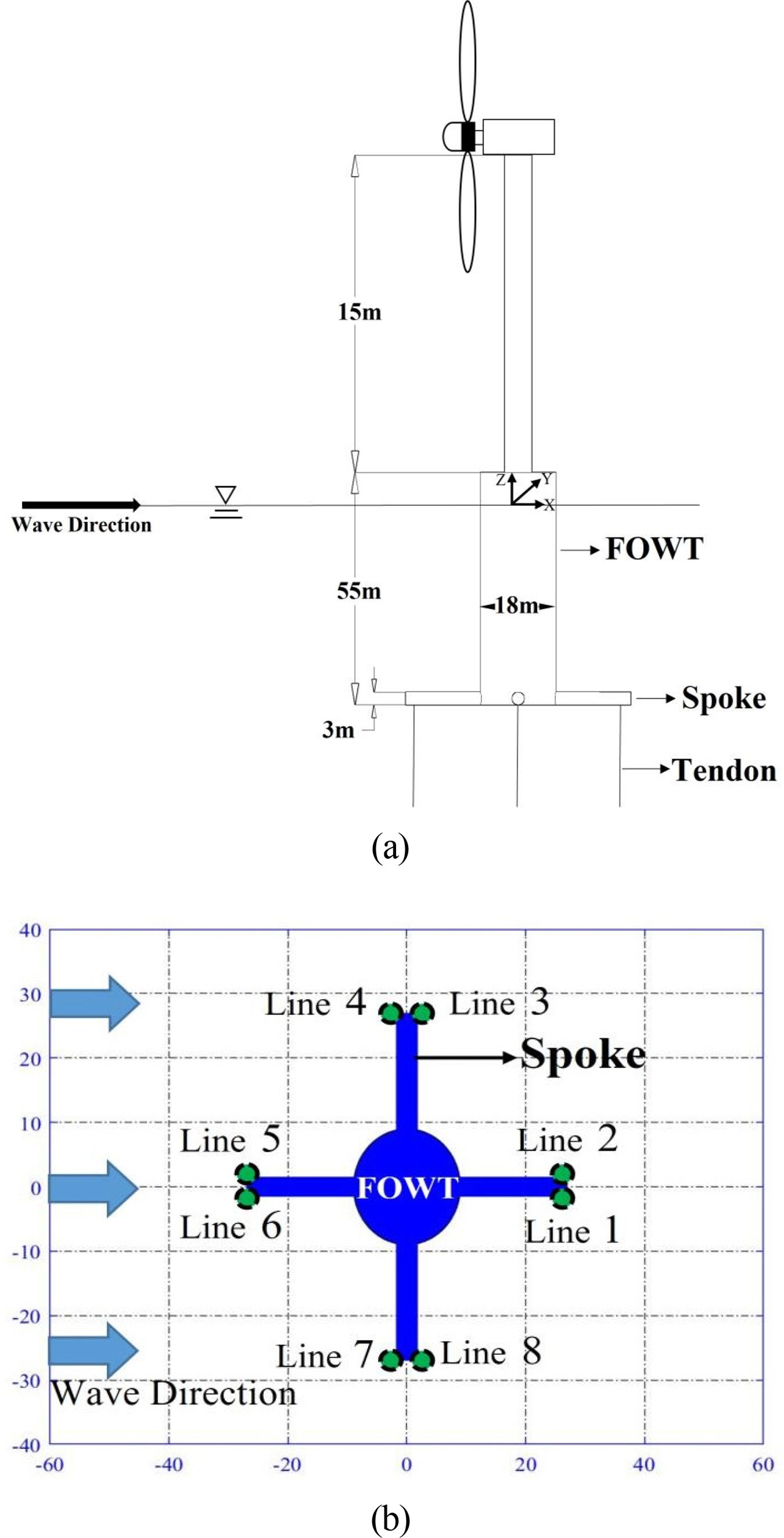
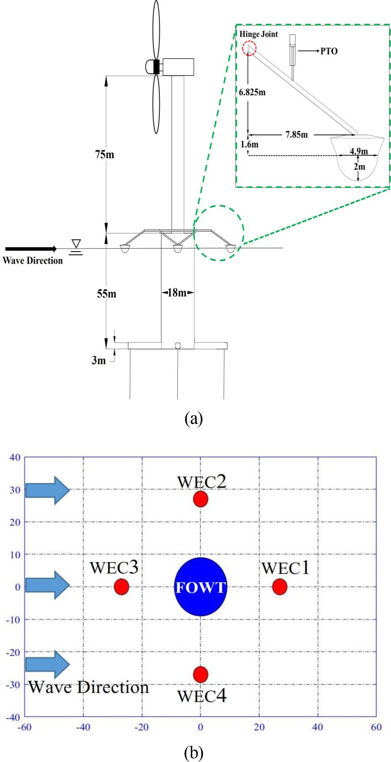
The motion response of the combined wind-wave energy platform was calculated by performing numerical modeling for the platform combining four hemispherical Wavestar-type WECs with a single TLP-type wind turbine model. Figs. 1 and 2 show the geometry of each numerical model and its main dimensions. Fig. 1(a) shows the single FOWT model, while Fig. 1(b) shows the mooring line layout. For this TLP-type structure, eight vertical tendons are connected from the spokes of the platform to the seabed. Fig. 2(a) shows the combined platform with WECs, while Fig. 2(b) shows the WEC layout. WEC3 is located in front of the incident wave direction, while WEC2 is located on the side of FOWT. In this study, the motion response of WEC3 and WEC2 and their interaction with FOWT were investigated because they are affected most significantly by the incident wave. The combined platform model and single platform model are the same TLP-type structures, and a 5MW-class wind turbine is attached to the top of the platform. As for the main dimensions of the wind turbine, the specifications provided by NREL (Jonkman et al., 2009) were used. In this study, however, the wind load was not considered, and the wind turbine and tower were assumed rigid bodies to identify the motion response characteristics of the platform under the 2nd-order wave loads.
Considering the specifications of TLP, the buoyancy of the floating body is larger than its weight, which causes the pretension of mooring lines. In other words, buoyancy can be expressed as the sum of the pretension of mooring lines and the weight of the floating body. Table 1 lists the mass properties of each structure and the specifications of mooring lines (Matha et al., 2010).
The natural frequencies of the combined and single FOWT models used in this study for surge, heave, and pitch were calculated through the free decay test, as listed in Table 2.
For the combined energy platform, four hemispherical buoy-type (Wavestar type) WECs were attached around the tower (FOWT). Each WEC was constrained with a hinge joint, so only one-dimensional rotational motion could be possible with respect to FOWT. A hydraulic cylinder was used as PTO acting on WEC; Table 3 lists its main specifications (Hansen et al., 2013). The hydraulic cylinder was installed at the 1/3 position of the arm. Coulomb damping force was used for the modeling of PTO system.
3. Numerical Analysis Method
Fig. 3 shows the process for calculating the motion response of the combined energy platform in the time domain. The WEC attached to FOWT is a hemispherical buoy-type (Wavestar type) that changes its wetted body surface depending on the wave motion. Therefore, it is important to calculate nonlinear external force considering the wetted surface of the floating body at each time step (Giorgi and Ringwood, 2018). In other words, the wave force is divided into a diffraction force and Froude–Krylov force, and a nonlinear Froude–Krylov force that considers the change in the wetted surface of the floating body was considered in this study. Therefore, the motion response of the platform was calculated by applying a nonlinear external force, and the AQWA-NAUT program capable of multi-body dynamics analysis was used to calculate the constraint force acting on FOWT due to the motion of the attached WEC.
In addition, a user subroutine was developed and calculated to apply the 2nd-order wave force that cannot be considered in the AQWA-NAUT program to the platform in time domain analysis. The time-series data of the 2nd-order wave force acting on FOWT were calculated by substituting the quadratic transfer function (QTF) of the external force calculated in AQWA-LINE into AQWA-DRIFT. They were applied to the combined energy platform at each time step to calculate its motion response. In addition, the Coulomb damping equation (Kim et al., 2021) was substituted by setting WEC PTO as a hydraulic cylinder model. In the section below, specific calculation formulas were described.
3.1 Hydrodynamic Force Calculation Process
A 2nd-order transfer function was obtained using AQWA-LINE to calculate the 2nd-order wave force acting on the platform. The boundary integral equation to solve the diffraction and radiation problems for deriving the 1st-order hydrodynamic coefficient is as follows. In addition, the boundary conditions of the platforme are given by Eq. (2).
Diffraction problem boundary integral equation
where ϕO is the incident wave potential; ϕS is the diffracted wave potential, and Sb is the wetted surface area of the structure. G indicates the Green function and n is the normal vector perpendicular to the surface of the body. The Green function used is expressed as Eq. (3).
Radiation problem boundary integral equation
The integral boundary equation to obtain the 1st-order radiation force coefficient is given by Eq. (4). In this case, the boundary conditions of the floating body are given by Eq. (5). ϕR is the radiated wave potential and ϕj is the radiated wave potential of the body according to each motion mode. ∊j is the unit amplitude of the body motion and j is the motion mode. j = 1 and 3 indicate the translational directions of the x-axis and z-axis, while j = 4 and 6 indicate rotational directions. In addition, when there are m floating bodies, including FOWT and multiple WECs, the radiated wave potential in consideration of the hydrodynamic interaction between each floating body can be expressed as a coupling term as in Eq. (5) through linear superposition.
3.2 Second-order Hydrodynamic Coefficient Calculation
The 2nd-order wave force of the combined platform (
F E X 2 F j k 2 = a j a k ( P j k + cos [ ( ω j + ω k ) t − ( α j + α k ) ] + Q j k + cos [ ( ω j + ω k ) t − ( α j + α k ) ] + P j k − cos [ ( ω j + ω k ) t − ( α j + α k ) ] + Q j k − cos [ ( ω j + ω k ) t − ( α j + α k ) ] ) P j k + Q j k + P j k − Q j k −
(7)
3.3 Equation of Motion of the Platform
To calculate the equation of motion of the combined energy platform in the time domain, the input values obtained through the user subroutine were substituted into AQWA-NAUT program. Eqs. (8) and (9) are the equations of motion that include all loads acting on FOWT and WECs.
where mF and mW are the masses of FOWT and WEC, respectively. mF,a and mW,a are the added masses of FOWT and WEC.
F F , F K 1 F W , F K 1 F F , DIFF 1 F W , DIFF 1 F F , E X 2 F W , E X 2
In addition, the Froude–Krylov force, which can be expressed as the incident wave force, is calculated for the wetted surface of the floating body that changes at each time step through the incident wave potential and Bernoulli equation, as shown in Eq. (10). The diffraction force was calculated considering the mean wetted surface area of the floating body through the diffracted wave potential and Bernoulli equation, as shown in Eq. (11).
In the time domain, the radiation-damping force can be calculated as a convolution integral, as shown in Eq. (12). ẋF(τ) and ẋW(τ) are the velocities of FOWT and WEC at time τ, respectively. The retardation function R(t) can be calculated using the radiation damping coefficient B(ω) as shown in Eq. (13). The radiation damping force can be calculated in the same way for both FOWT and WEC, which was calculated by applying each radiation damping coefficient.
The restoring force of FOWT consists of khydrostatic, which is the restoring force by the hydrostatic force acting on the floating body, and kmooring, which is the mooring restoring force caused by the mooring lines, as shown in Eq. (14). The restoring force of WEC includes the restoring force by a hydrostatic force and the PTO force (Eq. 21), as shown in Eq. (15). xF (t) and xW (t) are the displacements of FOWT and WEC at time t.
The translational and rotational forces acting on FOWT due to the motion of mooring lines are given by Eqs. (16) and (17) (Ran, 2000). [KL] is the linear stiffness matrix between FOWT and mooring lines, and [P̃] is the position matrix between FOWT and mooring lines. [Kθ] is the rotational stiffness matrix between FOWT and mooring lines, and [R̃] is the rotation matrix between FOWT and mooring lines. In addition, [C̃] and [D̃] are the translational and rotational motion matrices of FOWT.
FOWT and WEC are constrained by a hinge joint, as mentioned above. This causes FF,CONS and FW,CONS, which are constraint forces acting on FOWT and WEC, affecting the motion of FOWT and WEC, respectively. The constraint forces occur at the joint of FOWT and WEC, can be calculated using Eq. (18) (Ansys, 2016). Fj and Fk are the resultant forces acting on FOWT and WEC, excluding the constraint forces. [Uj] and [Uk] indicate the six-degree-of-freedom motions of FOWT and WEC, respectively.
[ K j j K j k K k j K k k ]
The PTO force acting on WEC was implemented through the Coulomb damping force equation (Kim et al., 2021). Gpto is the Coulomb damping force gradient according to the velocity of WEC. Δp and Sc are the pressure difference and cross-sectional area of the hydraulic cylinder of the PTO system, respectively.
where ż is the vertical velocity of WEC.
4. Numerical Analysis Results
4.1 Verification of the Motion Analysis of the Single Platform Model (FOWT-Only)
Before motion analysis of the combined energy platform model and the single platform model (FOWT-Only), the motion response of the single platform model to regular waves in the time domain was compared with the calculation results of FAST (Jonkman and Buhl, 2005), an open-source program provided by NREL, as shown in Fig. 4. The comparison was performed under the following conditions, and the validity of the calculation was verified: the representative condition of the target sea state (a wave height of 4 m and a wave period of 8 seconds) and the long wave condition (a wave height of 6 m and a wave period of 15 seconds) were considered in this study. In addition, the response of the platform for surge, heave, and pitch was compared while the wind load acting on the wind turbine was not considered, and the turbine and tower were assumed to be rigid bodies. The results were in good agreement with the FAST calculation results. The heave response, however, is slightly different from the FAST results. This result appears to be because the buoyancy of the spokes, which was not considered in the FAST model, was included in the TLP structures of the combined and single platform models. Therefore, the initial tension of mooring lines to offset this effect was increased by approximately 10% compared to the FAST model. In other words, the initial tension difference corresponding to the offset of the buoyancy of the appendage for the same calculation conditions partially affected the calculation results. In addition, each response is slightly different from the FAST results under the conditions of a wave height of 4 m and a wave period of 8 seconds. This result was attributed to the external force acting on the platform being slightly different from the nonlinear Froude-Krylov force. The nonlinear restoring force by the floating body motion was also included in this study. Nevertheless, there is no significant difference between the two calculation results, indicating that the analysis method used in this study is reliable.
4.2 Analysis of the Motion Responses of the Combined Energy Platform
Calculations were performed according to each load condition and WEC attachment to examine the effect of 2nd-order wave loads on the motion response of the combined energy platform. The wind load acting on the wind turbine was excluded in the analysis to precisely identify the influence of 2nd-order wave loads on the platform motion response. In this study, the following three load conditions were used: 1st-order wave load (LC1), 2nd-order difference-frequency wave load in addition to the 1st-order wave load (LC2), and both 2nd-order difference-frequency and sum-frequency wave loads in addition to the 1st-order wave load (LC3). Detailed load conditions are described in Table 4. These load conditions were applied to the combined and single platform models. Mooring line tension changes and characteristics of the motion response were mainly compared. The environmental conditions were selected by referring to a previous study that performed TLP analysis with specifications similar to this numerical model. The environmental conditions used were the JONSWAP spectrum with a significant wave height of 4 m, a peak period of 7.5 seconds, and a gamma of 2 (Bae and Kim, 2013). In addition, all incident waves were introduced in the x-axis direction.
The time-series data of motion response of the combined and single platform models were calculated in the time domain. They were converted to motion response spectra and compared in Fig. 5. Fig. 5(a) and 5(b) show the results of the surge responses of the platforms. For both the combined and single platforms, a large motion response occurred near the natural frequency (0.11 rad/s), while the response in the peak frequency of the incident wave (7.5 s = 0.83 rad/s) was negligible. When only the 1st-order wave load (LC1) was applied to the combined platform, the surge response was larger than that of the single platform. This is because the horizontal force acting on the entire platform is larger than the single platform under the influence of WECs. The surge response of the single platform tended to be larger when LC2 was applied than when LC1 was applied. The response of the single platform in the natural frequency range decreased when LC3 was applied compared to when LC2 was applied. In the case of the combined platform, however, the magnitude of the surge response in the natural frequency range hardly changed regardless of the presence or absence of the 2nd-order wave load. This is because the WEC PTO of the combined platform offsets the effect of the 2nd-order sum-frequency load.
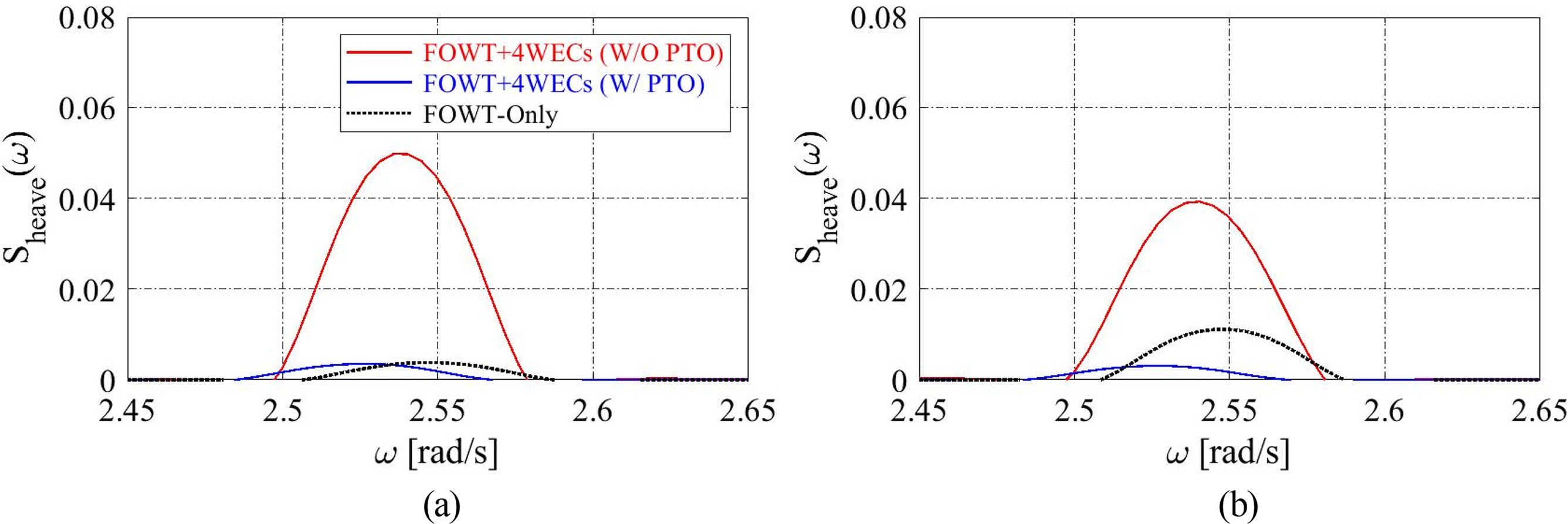
Fig. 5(c) and 5(d) compare the heave responses of the platforms. Similar to the surge response, the heave response was large in the natural frequency range (2.5 rad/s). This indicates that a large response occurred at the natural frequency because of the characteristics of the TLP platform. The magnitude of the response was negligible in the peak frequency range of the incident wave (0.83 rad/s) because it was far from the natural frequency of the platform. For both the combined and single platforms, the magnitude of the heave response did not change significantly when LC1 and LC2 were applied. When LC3 was applied to the single platform, however, the magnitude of the heave response was increased by approximately three times. This result was attributed to a phenomenon in which the load increases under the influence of the slowly decaying second-order pressure field as the incident wave is reflected from the cylinder-shaped floating body, and it has already been reported in several studies (Min and Koo, 2022; Koo and Kim, 2007; Kim, 1993, Kim and Yue, 1989). The motion characteristics of TLP structures respond to 2nd-order sum-frequency wave loads. In the case of the combined platform model with WECs, however, the effect of the 2nd-order sum-frequency wave load can hardly be observed. This appears to be due to the influence of WEC PTO, and the analysis of this phenomenon is described below.
Similar to surge and heave responses, the pitch responses of the platforms (Fig. 5(e) and 5(f)) were observed in the pitch natural frequency of the floating body (1.7 rad/s) and the peak frequency of the incident wave (0.83 rad/s). The magnitude of the pitch response at the peak frequency, however, is similar to that at the natural frequency. This appears to be because the peak frequency of the incident wave is relatively close to the natural frequency, and a relatively large pitch occurs in the incident wave spectrum. No significant change was observed in the pitch response under the application of the 2nd-order wave loads for single and combined platforms. The pitch response, however, slightly increased in the combined platform compared to the single platform. This result was attributed to the motion response (pitch) of WECs in the peak frequency (0.83 rad/s), as mentioned in section 4.3, affecting the pitch increase of the combined platform. WEC attachment also appears to slightly increase the pitch of the combined platform in the pitch natural frequency (1.7 rad/s) of the floating body.
Therefore, regarding the surge response of the TLP-type platform, the motion of the single platform model tends to increase under the influence of 2nd-order wave loads. In particular, when the 2nd-order sum-frequency wave load was applied, the heave response in the natural frequency range tended to increase dramatically. The heave of the combined platform with WECs was not affected significantly by the 2nd-order wave loads. In the case of pitch, the influence of the 2nd-order wave loads was negligible for both models, but the response of the combined platform was slightly larger than the single platform.
4.3 FOWT and WEC Motion Analysis According to the Presence or Absence of WEC PTO
The heave of the single platform model was significantly increased by the 2nd-order sum-frequency wave load, but its effect on the combined platform was insignificant. This reason can be explained by the influence of the PTO acting on WEC. Fig. 6 compares the heave response spectra of the combined platform when the WEC PTO force was excluded (w/o PTO) and added (w/ PTO). For the combined platform under the application of LC1, the heave of the platform was significantly reduced when the PTO force was added (Fig. 6(a)). The application of the PTO force also reduced the heave of the combined platform significantly under the application of LC3 (Fig. 6(b)). The PTO force made the heave of the combined platform smaller than that of the single platform when LC3 was applied. Hence, the PTO force in the combined platform serves as a motion damper that attenuates the heave of the platform.
Fig. 7 compares the rotational motion response spectra of WECs according to the application of the PTO force. WECs operate one-dimensional rotational motion because they are connected to the platform through arms, and the arms are connected to the platform using hinge joints. As shown in Fig. 2, the direction of the motion of WEC2 is perpendicular to the incident wave, while WEC3 is located in front of the incident wave direction. The motion response of WEC2 is similar to that of WEC4 because the arrangement of WECs is symmetrical with respect to FOWT. The response of WEC3, which is expected to be most significantly affected by the incident wave, was analyzed. The WEC showed responses at the surge natural frequency of FOWT (0.11 rad/s), half the peak frequency of the incident wave (0.4 rad/s), and the peak frequency of the incident wave (0.83 rad/s). The motion response of WECs is significantly large when the PTO force is not applied, but the application of the PTO force rapidly decreases the responses in all frequency ranges. Therefore, the PTO force sharply decreases the overall motion response of WECs, and only the response in the peak frequency range of the incident wave occurs (Figs. 7(c) and 7(d)). The rotational response of WECs was slightly larger when LC3 was applied than when LC1 was applied. It appears that the WEC motion response occurred in the surge natural frequency range of the FOWT platform (0.11 rad/s) because WECs are attached to the platform and are thus partially affected by the surge of the platform.
The response that occurs at half the peak frequency of the incident wave is affected by the nonlinear Froude–Krylov force and the nonlinear restoring force of the floating body, and the steepness of the incident wave (Yang et al., 2020). This phenomenon can be explained by the WEC response being reduced rapidly at half the peak frequency of the incident wave if calculation is performed by fixing the wetted surface of the floating body (linear calculation).
In summary, a comparison of the motion response of the combined platform and WECs according to the presence or absence of PTO confirmed that PTO serves as a heave motion damper of the combined platform and reduces the WEC motion rapidly in all frequency ranges. In addition, as can be seen from the condition without PTO, the WEC motion is affected by the surge natural frequency of FOWT (0.11 rad/s), but FOWT is unaffected by the natural frequency of hinged WECs (1.26 rad/s). This indicates that the influence of WECs is limited because their size and weight are very small compared to those of FOWT. Moreover, the motion response is larger under the 2nd-order wave load condition than the 1st-order wave load condition, regardless of the presence or absence of PTO.
4.4 Platform Mooring Line Tension Analysis
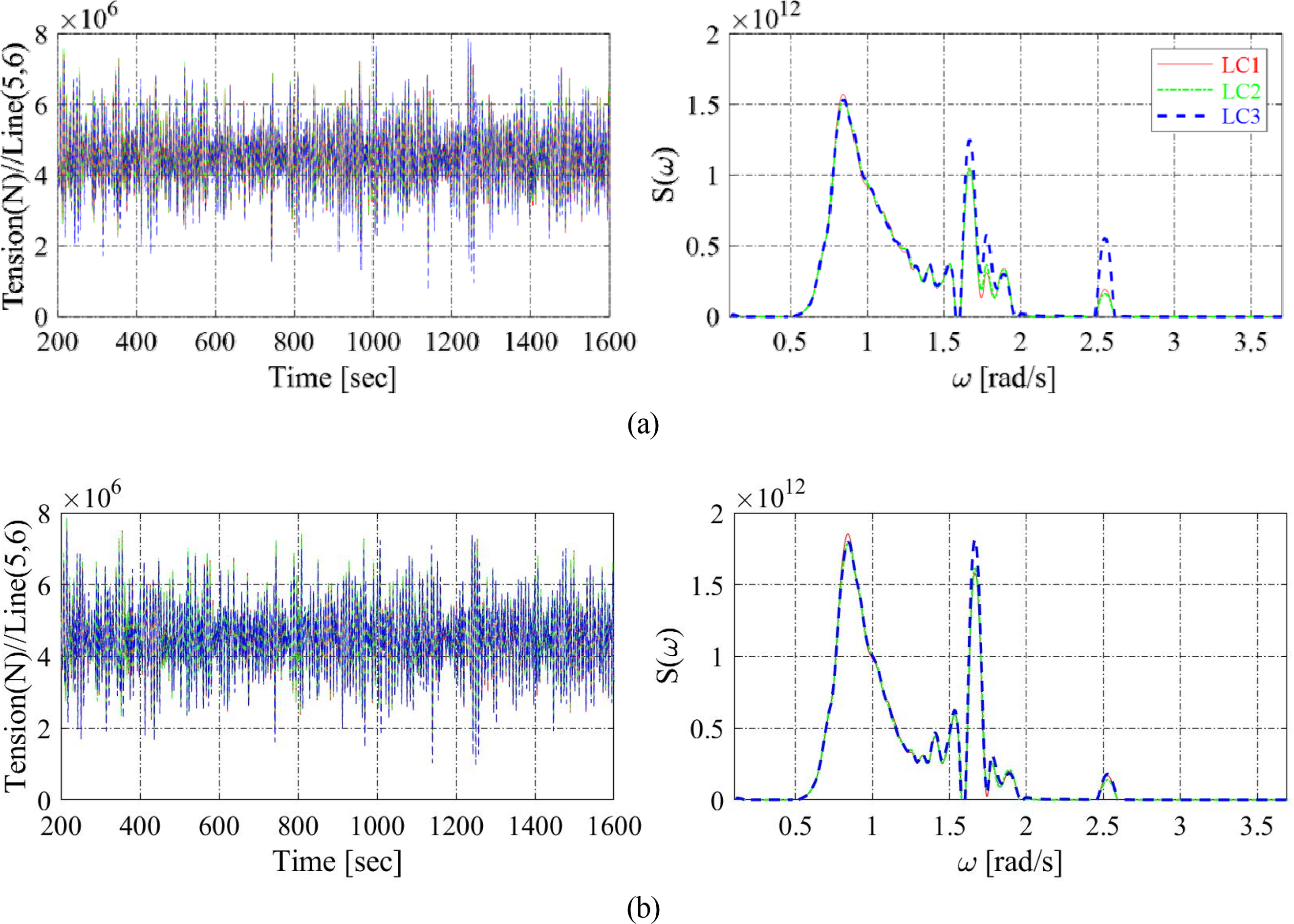
From the mooring line layout in Fig. 1(b), two mooring lines are vertically attached to each of the four spokes. Figs. 8 and 9 compare the time-series data and spectrum for mooring line tension according to the floating body motion. Because the arrangement of mooring lines is symmetrical with respect to FOWT, as with the arrangement of WECs, the results of mooring lines 3 and 4 will be similar to those of mooring lines 7 and 8. The tension of mooring lines 5 and 6, which are expected to be significantly affected by the incident wave, was analyzed. Mooring lines 5 and 6, located in front of the incident wave direction, showed a similar tendency to that of the pitch response spectrum of the platform. An additional response was also observed in the natural frequency range of the heave response spectrum of the platform (2.5 rad/s). This suggests that mooring lines 5 and 6 are affected most significantly by the pitch of the platform and by the heave of the platform to some extent because of their location. Therefore, the mooring line tension in front of the incident wave direction is affected significantly by the 1st-order wave load, and the influence of the 2nd-order wave loads is insignificant.
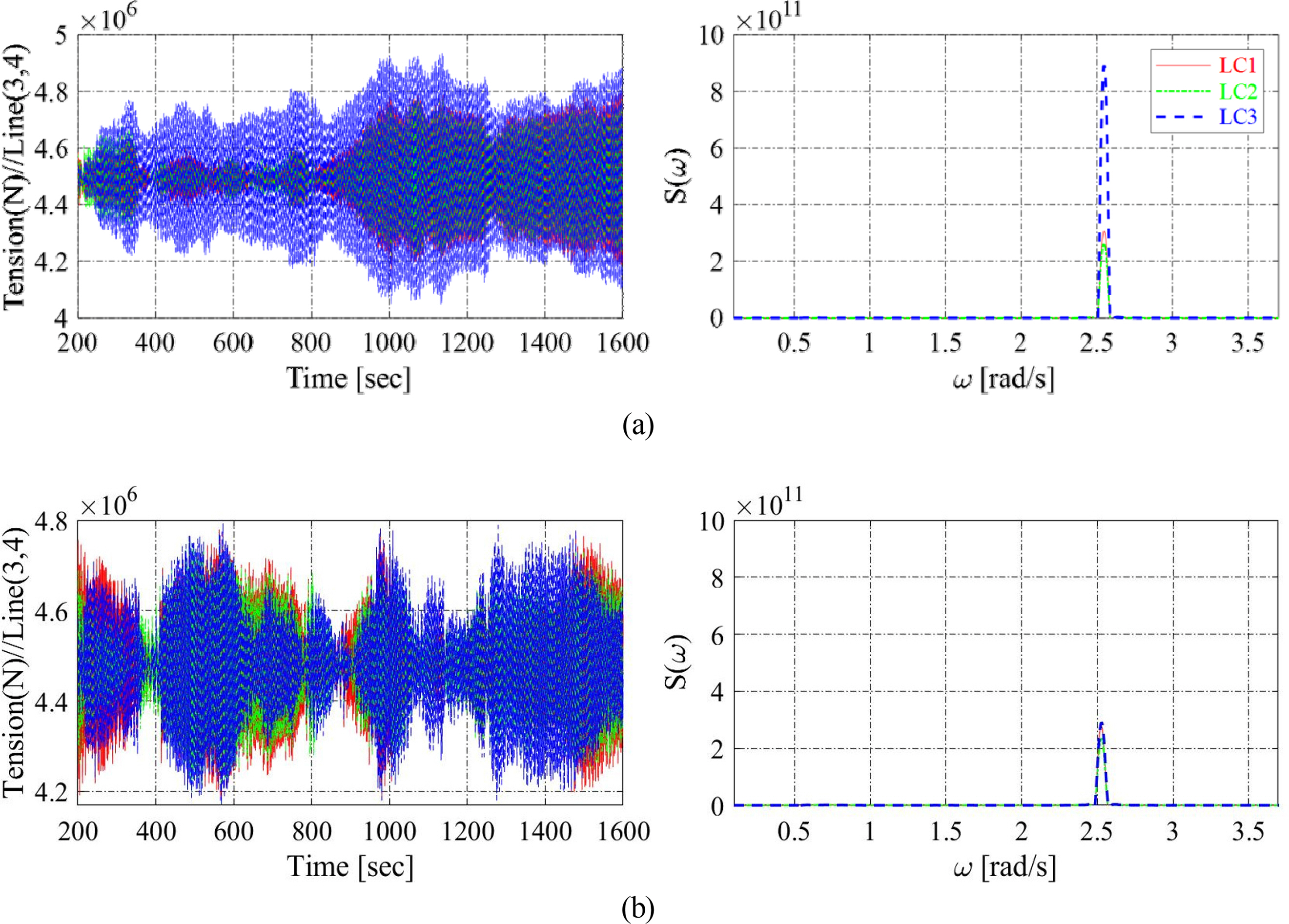
Fig. 9 compares the tension time-series data and spectrum for mooring lines 3 and 4, which were installed on the side of the floating body. They generally showed a similar tendency to that of the heave response spectrum of the platform for both the combined and single platforms. This suggests that the mooring lines are affected by the heave of the platform and hardly affected by the surge or pitch of the platform, which can be expected. Therefore, the influence of the 2nd-order sum-frequency wave load (LC3), which had a significant impact on the increase in heave of the single platform, acted similarly on mooring lines 3 and 4, increasing the mooring line tension by approximately three times (Fig. 9(a)). This also applies to mooring lines 7 and 8, which are symmetrically installed.
In summary, the mooring line tension in front of the incident wave direction was dominantly affected by the pitch of the platform and partially affected by the heave of the platform. The mooring line tension on the side of the floating body was dominantly affected by the heave of the platform, and the mooring line tension of the single platform (FOWT-Only) increased rapidly under the influence of the 2nd-order sum-frequency wave load.
5. Conclusion
In this study, motion characteristics were analyzed by applying 2nd-order wave loads to identify the precise motion response of a combined wind-wave energy platform based on the TLP structure. The motion response characteristics of single and combined platforms were compared to analyze the change in the motion response of the platform due to the attachment of Wavestar-type WECs. ANSYS AQWA, a hydrodynamic program, was used. A user subroutine was developed for time-domain analysis of the effect of 2nd-order wave loads and WEC PTO damping force acting on the combined energy platform.
The surge response of the platform was large in the natural frequency range for both the combined and single platforms, and the response in the peak frequency range of the incident wave was insignificant. Regarding the motion response of the platform under the application of the 2nd-order wave loads, the heave response was found to be large. In particular, the magnitude of the heave response of the single platform increased by approximately three times under the 2nd-order sum-frequency wave load. This is because of the influence of the slowly decaying second-order pressure field as the incident wave is reflected from the cylinder-shaped floating body, which was the motion characteristic of the TLP structure. The motion response of the combined platform model, however, was barely affected by the 2nd-order sum-frequency wave load because of the influence of the WEC PTO force. The PTO force serves as a heave damper of the combined platform, decreasing the WEC motion in all frequency ranges. The motion response of WECs was slightly larger when the 2nd-order wave load was applied than when the 1st-order wave load was applied. The mooring line tension in front of the incident wave direction was dominantly affected by the pitch of the platform and partially affected by the heave of the platform. The mooring line tension on the side of the platform was dominantly affected by the heave of the platform, and the mooring line tension of the single platform increased rapidly under the influence of the 2nd-order sum-frequency wave load.
This study identified the motion response characteristics of the TLP-type combined wind-wave energy platform according to the attachment of WECs and the influence of 2nd-order wave loads. Through the identification of such motion response characteristics, it is possible to control the excessive mooring line response of the TLP-type wind turbine platforms due to the 2nd-order wave loads and to seek more stable energy extraction. Based on this, the motion response characteristics of combined platforms will be analyzed under realistic ocean environmental conditions by adding the aerodynamic load acting on the wind turbine.