 |
 |
- Search
| J. Ocean Eng. Technol. > Volume 36(2); 2022 > Article |
|
Abstract
This paper presents the minimum submergence depth of an underwater vehicle that can remove the effect of free surface on the resistance of the underwater vehicle. The total resistance of the underwater vehicle in fully submerged modes comprises only viscous pressure and friction resistances, and no wave resistance should be present, based on the free surface effect. In a model test performed in this study, the resistance is measured in the range of 2 to 10 kn (1.03–5.14 m/s) under depth conditions of 850 mm (2.6D) and 1250 mm (3.8D), respectively, and the residual resistance coefficients are compared. Subsequently, resistance analysis is performed via computational fluid dynamics (CFD) simulation to investigate the free surface effect based on various submergence depths. First, the numerical analysis results in the absence of free surface conditions and the model test results are compared to show the tendency of the resistance coefficients and the reliability of the CFD simulation results. Subsequently, numerical analysis results of submergence depth presented in a reference paper are compared with the model test results. These two sets of results confirm that the resistance increased due to the free surface effect as the high speed and depth approach the free surface. Therefore, to identify a fully submerged depth that is not affected by the free surface effect, case studies for various depths are conducted via numerical analysis, and a correlation for the fully submerged depth based on the Froude number of an underwater vehicle is derived.
Recently, the use of underwater vehicles has increased in various fields, e.g., the exploration and development of marine resources, military purposes including marine surveillance and reconnaissance, and marine environment monitoring. As a maritime country surrounded by sea on three sides, South Korea must secure and further develop its marine resources via the research and development of underwater-related technology, including underwater vehicles (Choi and Kim, 2012).
Herein, we discuss the resistance of an underwater vehicle in fully submerged modes (i.e., fully submerged modes without the free surface effect, or the unbounded condition). Because fully submerged modes involve no free surface effect from water, the total resistance comprises only viscous pressure and friction resistances (Moonesun, 2009). To realize such fully submerged modes, the underwater vehicle must operate at a sufficient depth.
Jackson(1982) dealt with research on the overall design process of a underwater vehicle, and the minimum depth suggested in this paper is H = 3D (D = Hull diameter). The drag and lift forces of various underwater vehicles have been investigated through experiments and numerical analysis, and the standard depth for the fully submerged condition of each underwater vehicle varies among the reference papers.
Rawson and Tupper (2001) showed that because an underwater vehicle has a larger wetted surface area than a regular merchant ship for a certain displacement, it demonstrates greater frictional resistance and hence must operate at a depth that does not result in wave-making resistance. They defined the minimum depth condition as H =L/2 (L = hull length).
Meanwhile, Jackson (1982) presented the overall design process of underwater vehicles and suggested a minimum depth of H = 3D (D= hull diameter).
Moonesun et al. (2013) performed a comparative analysis and a computational fluid dynamics (CFD) analysis of results obtained by changing various conditions of the International Towing Tank Conference analysis method during the model testing of a target underwater vehicle; the minimum depth was set to H = 5D.
Javadi et al. (2015) experimentally investigated the effect of the movement of an autonomous underwater vehicle (AUV) on resistance based on the bow shape. They used two different shapes—tango and standard shapes—and analyzed the total, residual, and frictional resistances at Froude numbers (Fn ) from 0.099 to 0.349. The results showed that the residual resistance of the standard shape exceeded that of the tango shape at from 0.19 to 0.3.
Mansoorzadeh and Javanmard (2014) performed single- and two-phase flow simulations without free surface to investigate the effect of free surface on the drag and lift coefficients of an AUV based on experiments and the CFD method. They conducted the study at various test depths of the model for AUV diameters ranging from 0.87 to 5.22, at two speeds of 1.5 and 2.5 m/s.
Nematollahi et al. (2015) numerically investigated the interaction between a free surface and a symmetrical AUV. The study was conducted at various Reynolds numbers of various depths. They showed that when the Reynolds number was fixed, not only the pressure drag, but also the resistance coefficient increased when the Fn decreased, and that the effect of free surface is negligible when H is greater than or equal to 3D. Furthermore, they confirmed that if the Reynolds number increases at a low submergence depth, then the effect of underwater vehicle motion on the free surface becomes more evident.
The standard values for submergence depths are difficult to present because they may vary depending on the vessel shape and velocity, i.e., the Fn. However, we conducted this study based on our assumption that the depth can be expressed by a function of the Fn if the underwater vehicles exhibit similar shapes. Many types of underwater vehicles exist, including underwear vehicles and submarines. However, for the underwater vehicle used in this study, we assumed that the characteristics of the vessel shape will not vary significantly.
The aim of this study is to propose a new standard depth at each Fn for an underwater vehicle with L/D =5.8 based on resistance test results obtained via model tests and CFD simulation. Experiments were conducted in a towing tank at Pusan National University (PNU). By comparing experimental fluid dynamics (EFD) and CFD analysis results, we demonstrate the reliability of the CFD analysis and propose a standard depth, at which the effect of free surface is negligible, for each Fn by comparing the CFD analysis results with the no-free-surface condition and the resistance results at various depths with a free surface condition.
Model tests on a submerged body are typically difficult to conduct at a sufficient depth because of various constraints; however, the results of this study can be used as a reference for the standard submergence depths of underwater vehicles.
We conducted model tests using a scaled-down model of the underwater vehicle in a towing tank at Pusan National University. The towing tank measured 100 m long, 8 m wide, and 3.5 m deep, and the maximum speed of the towing carrier was 7 m/s. The ratio of the underwater vehicle’s fuselage length to the diameter was L/D =5.8.
The experiment was conducted for two depths: 850 mm (2.6D) and 1,250 mm (3.8D). The total resistance was measured at intervals of 1 kn (0.514 m/s) at the vehicle speed range of 2 to 10 kn (1.03–5.14 m/s). Fig. 2 shows the towing carrier at PNU and the experimental setup used for the model tests. Sandpaper was attached as a turbulence stimulator at a length between perpendiculars (LPP) position of 0.05 on the model vehicle’s bow. The towing carrier and model vehicle were connected using two cylinders (diameter of cylinder = 5 cm), where a transparent polyvinyl chloride plate was attached to prevent disturbance from the free surface due to the connecting section of the load cell and the model vehicle.
The resistance test was conducted at intervals of 1 kn (0.514 m/s) at the vessel speed range of 2 to 10 kn (1.03–5.14 m/s); the experiment was repeated twice with different depths. The total resistance was measured at a depth of 850 mm (2.6D ) in the first experiment and at a depth of 1,250 mm (3.8D ) in the second experiment. The results are shown in Tables 2‒3 (Rn is the Reynolds number, CR the residual resistance coefficient, and RTM the total resistance of the model vehicle).
The experimental results obtained based on a depth of 850 mm (2.6) as well as the residual resistance coefficient, which increased gradually at high speeds, indicate that the wave-making resistance was due to the free surface. Subsequently, we conducted the experiment again at a depth of 1,250 mm (3.8D) based on a reference, which was unbounded by the effect of free surface.
The experimental results based on a depth of 1,250 mm (3.8D) indicate that as the speed increased, the residual resistance coefficient increased less as compared with the residual resistance coefficient at a depth of 850 mm (2.6D). Fig. 3 shows a graphical comparison of the residual resistance coefficient values between the two depths.
These two sets of results confirm that the resistance may change sensitively depending on the submergence depth as a result of the wave-making resistance due to the free surface. Because we could not conduct the experiment at a depth exceeding 1,250 mm owing to the condition of the PNU towing tank, we performed CFD analysis to analyze the difference in resistance based on the free surface conditions.
In this study, we used STAR CCM+ (Ver. 11. 02) to perform the numerical analysis. In terms of the coordinate system applied to the CFD analysis, the positive (+) x-axis represents the flow direction, the positive y-axis represents the starboard of the underwater vehicle, and the positive z-axis represents the opposite direction of gravity.
A continuous equation and a Reynolds averaged Navier–Stokes equation, which are the dominant equations of three-dimensional non-compressible turbulent flow, are used in the simulation. They are expressed as follows:
where ρ is the density of the fluid, t the time, ui the flow rate, p the pressure, μ the fluid viscosity coefficient, gi the gravitational acceleration,
ρ u i ' u j ' ¯
Turbulence models can be classified into zero-equation, one-equation, and two-equation models depending on the number of turbulence-related equations to be solved additionally. The realizable k−∊ model is the most typically used model in engineering. In this study, we used the realizable k− ∊ turbulence model, which showed improved performance for the boundary layer separation flow caused by the adverse pressure gradient. In the free surface analysis, we used the volume of fluid (VOF) method. The VOF method is a method that monitors the position of the free surface, which is the boundary between two fluids, based on the volume ratio of the two fluids, which have different densities in the grid (Jagadeesh and Murali, 2010).
The analysis domain and boundary conditions used in this study are shown in Fig. 4. As boundary conditions, an inlet at the bow and velocity inlets on the bottom and top were established, and the outlet where the flow exited was set as a pressure outlet. The size of the domain was defined for the LPP.
A trimmed mesh and a prism layer were used to create the underwear vehicle’s surface and the space grids. The number of grids was approximately 1.03 million when the resistance performance was considered, whereas it was approximately 990,000 when no free surface was involved. Fig. 4 shows the grid system, and for the first position of the grid points located on the surface, we assumed that it was at approximately y+ = 50. Meanwhile, because the effect of shear force was significant around the underwater vehicle, six layers were established in the prism layer, and the wall function was applied (Byeon et al., 2018).
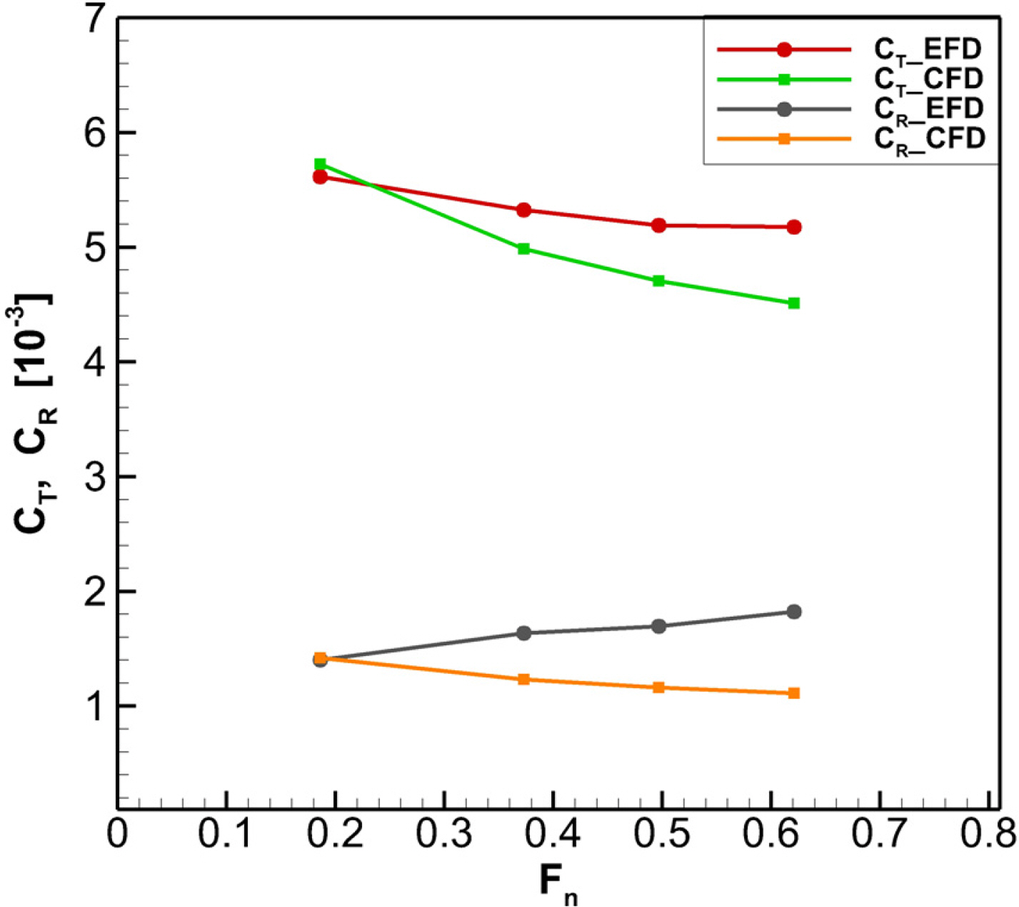
Next, we compare the results obtained by conducting the model test with a free surface condition at 3.8D depth and the CFD analysis results without the free surface condition. Table 4 and Fig. 5 show the differences in resistance coefficient and total resistance at vehicle speeds of 3, 6, 8, and 10 kn (1.54, 3.09, 4.12, and 5.14 m/s, respectively). Based on the result where the difference in total resistance at a low speed of 3 kn (1.54 m/s) was −0.25%, we conducted a CFD analysis under the same conditions for different vehicle speeds. The results show that as the speed increased, the differences in resistance coefficient and total resistance increased. The experimental results based on a low speed of 3 kn (1.54 m/s) were consistent with the CFD results for the no-free-surface condition because almost no wave-making resistance caused by free surface was present. Furthermore, the effect of wave-making resistance became dominant when approaching a high speed.
The results shown in Table 4 and Fig. 5 suggest that the difference in the resistance coefficient at high speed was caused by the wave-making resistance arising from the free surface; additionally, the experiments did not satisfy the standard depths of the fully submerged condition. Therefore, we conducted a CFD resistance analysis by changing the submergence depth at a specified speed of 10 kn (VS = 5.14 m/s, VM = 2.71 m/s). A comparative analysis was performed for the EFD and CFD results under the following four depth conditions: H = 3D and H = 5D, which are suggested in a previous study; H = 3.8D, which is a depth at which the model test was conducted at PNU; and without any free surface condition (non-F.S.E.) (F.S.E.= free surface effect). Table 5 shows the results.
As shown by the CFD results in Table 5 below, the size of the total resistance decreases as the submergence depth increases. Additionally, the free surface effect differs significantly based on the submergence depth at a high speed of 10 kn (VS = 5.14 m/s, VM = 2.71 m/s), which suggests that the mode test was not conducted at a sufficient depth.
The results of the model test and CFD analysis shown in Tables 4 and 5 confirm that the difference in total resistance caused by the free surface effect is significant between the submergence depths, and that the effect becomes more prominent as the speed increases.
Next, we conducted a CFD resistance analysis to examine the correlation between the vehicle speed and submergence depth to identify the standard depth that satisfies the fully submerged condition for each vehicle speed; subsequently, we comparatively analyzed the results. The analysis was conducted for four vehicle speeds of 3, 6, 8, and 10 kn (1.54, 3.09, 4.12, and 5.14 m/s, respectively), and case studies were conducted at various depths with the free surface condition in reference to the results obtained without any free surface condition. Table 6 shows the results for cases involving a free surface condition (F.S.E.) and no free surface condition (non-F.S.E.).
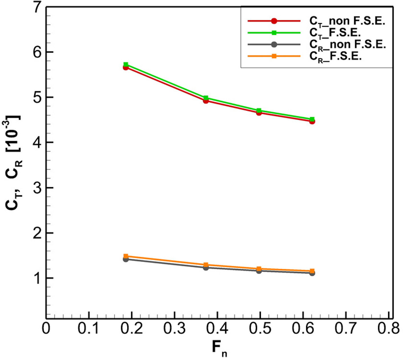
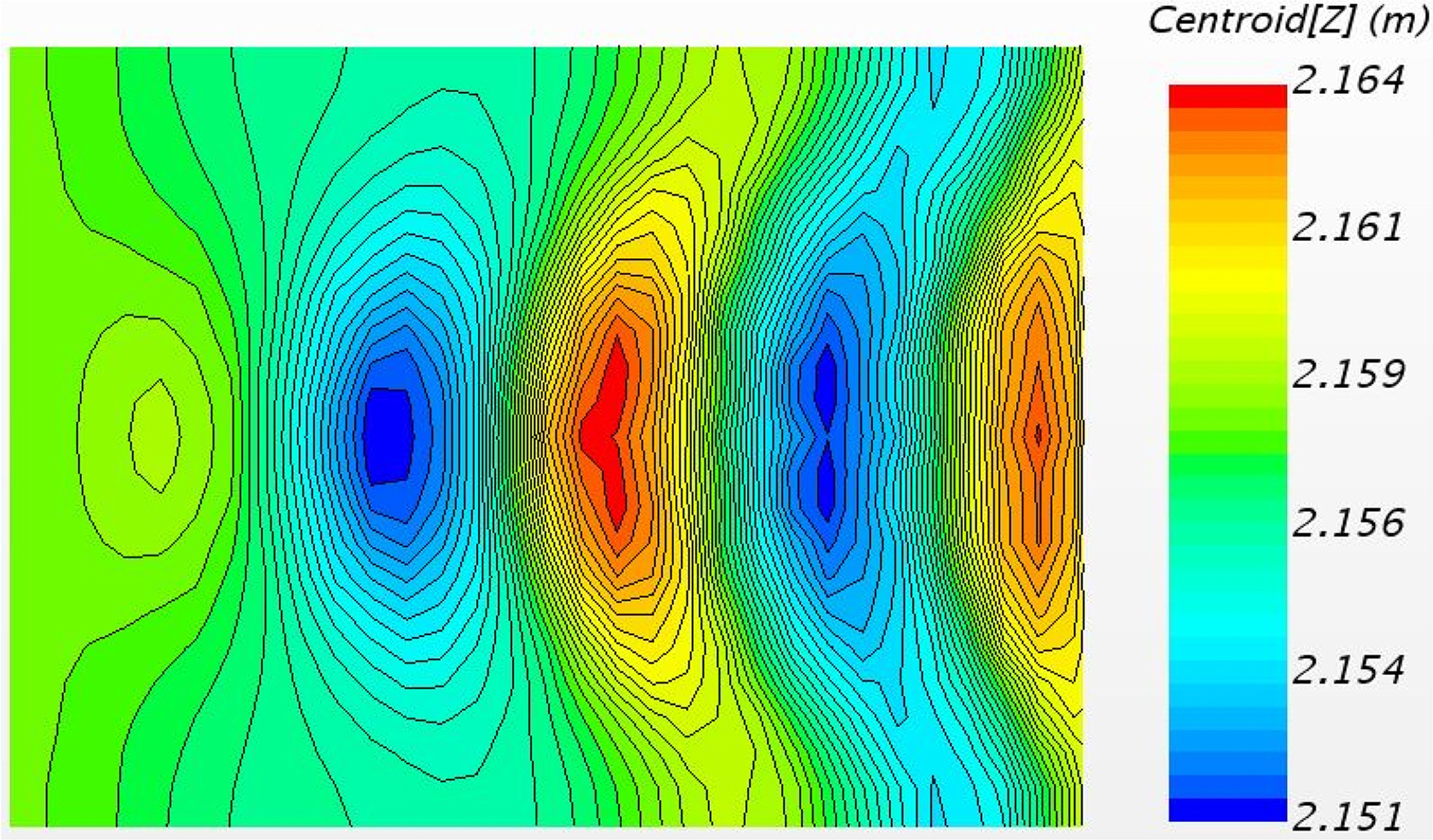
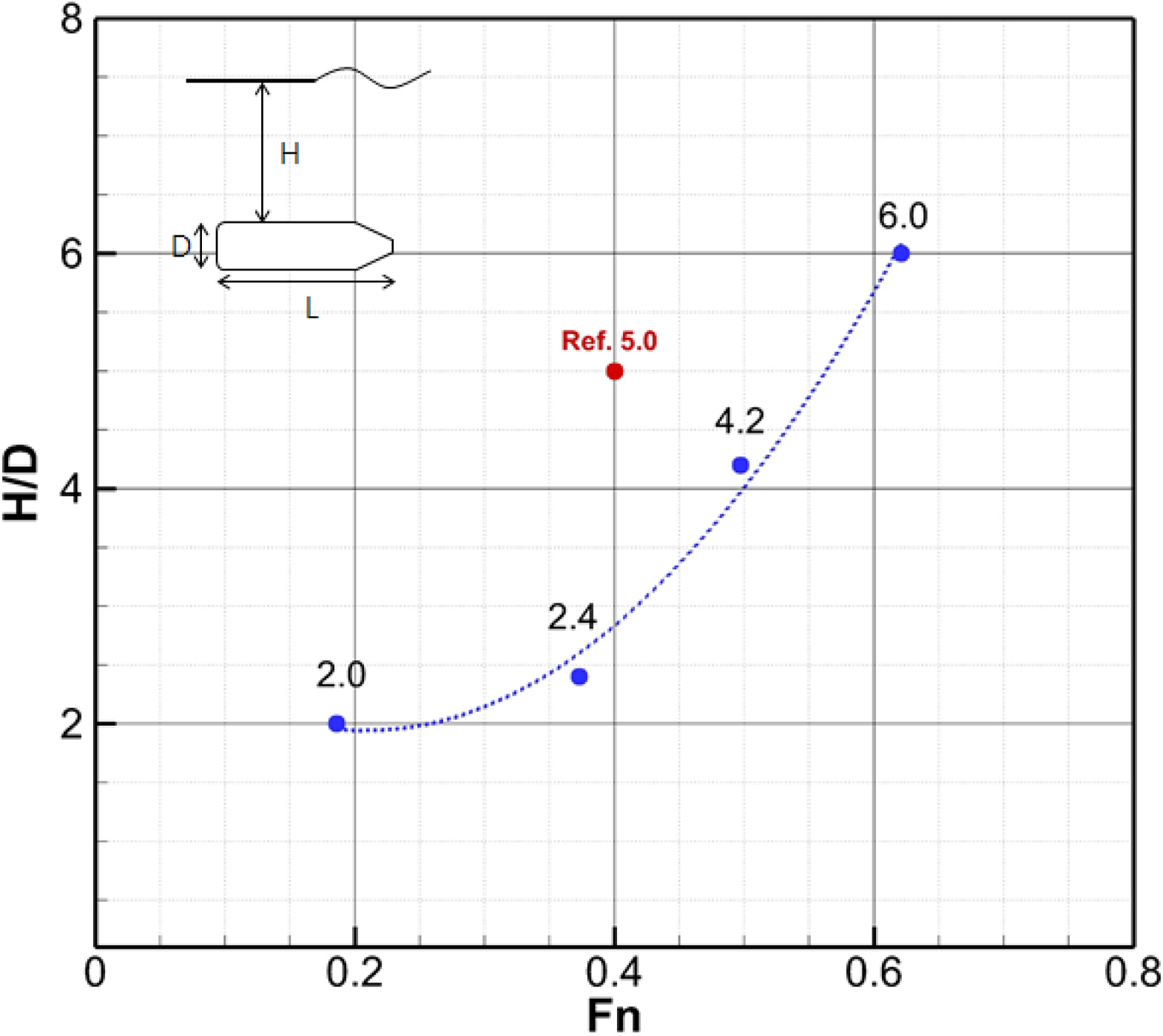
For each vehicle speed, the standard depth for the fully submerged condition of the underwater vehicle was set to a depth at which the difference in the CFD resistance analysis results, i.e., the difference between the results of F.S.E. and non-F.S.E., was less than 1%. As shown in Table 7, the results are 2.0D at VS = 3 kn (1.54 m/s), 2.4D at VS = 6 kn (3.09 m/s), 4.2D at VS = 8 kn (4.12 m/s), and 6.0D at VS = 10 kn (5.14 m/s). The graph in Fig. 6 shows the difference in the resistance coefficient between the EFD and CFD results based on the . Furthermore, Fig. 7 shows the waveform of the free surface in the z-direction for VS = 10 kn (5.14 m/s) and H = 6.0 (the z-position of the free surface in the CFD simulation is 2.158 m.)
For each vehicle speed, the appropriate submergence depth at which free surface imposes no effect was set to the depth at which the difference in resistance coefficient between the non-F.S.E. and F.S.E. results was less than 1%. The vehicle speed and depth were non-dimensionalized into Fn and H/D, respectively, and their correlation is shown graphically in Fig. 8. The x-axis of the graph in Fig. 8 represents Fn, and the y-axis represents the ratio of the submergence depth to the hull diameter (H/D). The results for the appropriate submergence depths at four Fn of the underwater vehicle are shown in a trend line. Furthermore, a comparison between the current results and those obtained based on Fn = 0.4 and H = 5.0D by Moonesun et al. (2013) suggest that the experiments were conducted at a deeper level than the required depth determined in this study. However, a deeper level may be required when Fn is large (i.e., when the underwater vehicle exhibits a high vehicle speed or a small L).
The effect of free surface based on the submergence depth of an underwater vehicle was investigated in this study. Model tests and CFD analysis were performed to determine the total resistance and resistance coefficients of the underwater vehicle.
The underwater vehicle’s L/D was 5.8, and the experiment was conducted twice at depths of 850 mm (2.6D) and 1,250 mm (3.8D ), intervals of 1 kn (0.514 m/s), and a vehicle speed range of 2 to 10 kn (1.03–5.14 m/s). In terms of the residual resistance coefficient, the results obtained at a depth of 850 mm (2.6D ) were higher than those obtained at a depth of 1,250 mm (3.8D) as the speed increased. Hence, we inferred that the wave-making resistance might have been caused by the free surface effect arising from the difference in depth. We conducted a CFD resistance analysis to verify the difference in the free space effect between the depth conditions. First, we compared the total resistance obtained via CFD simulation without a free surface and that obtained experimentally. The result showed that the difference in the total resistance was −0.25%, which is insignificant, at a low speed of 3 kn (1.54 m/s); however, the difference increased gradually to 13.75% at a high speed of 10 kn (5.14 m/s), and the difference in the residual resistance coefficient increased as well. In our opinion, this error occurred because the standard depth, at which the free surface imposed no effect, was not satisfied in the high-speed domain in the experiments; therefore, we examined the difference in the total resistance based on the submergence depth at specified speeds. We investigated four depths: depths of 3D and 5D, as suggested in a reference paper; a depth of 3.8, which was applied for an experiment performed in the PNU towing tank; and the no-free-surface condition. The CFD analysis results obtained based on these depths were compared with the EFD results. The results showed that as the depth from the free surface increased, the total resistance from the CFD results decreased and, consequently, the error from the model test result increased. Therefore, based on the two sets of results above, we concluded that the values measured in the model test were high owing to the effect of the free surface because the model test was not performed at a sufficient depth, and that the effect was more prominent in the high-speed domain.
We conducted case studies by performing CFD simulations based on various depths of the free surface for each vehicle speed to identify a submergence depth at which the free surface effect was absent. A depth at which a difference of less than 1% was indicated between the F.S.E. and non-F.S.E. cases was set as the appropriate depth. The standard depths of the underwater vehicle without the effect of free surface were defined as follows: 2.0D at VS = 3 kn (1.54 m/s), 2.4D at VS = 6 kn (3.09 m/s), 4.2D at VS = 8 kn (4.12 m/s), and 6.0D at VS = 10 kn (5.14 m/s). Furthermore, the vehicle speed and submergence depth were non-dimensionalized into Fn and H/D, respectively, and the correlation was formulated as y = 24x2 − 10x + 3.
We confirmed that the results varied significantly because of the free surface effect due to the submergence depth and. The sufficient depth may change depending on the shape of the underwater vehicle; however, if the shape does not differ significantly from that of the underwater vehicle applied in this study, then the results of this study can be applied to the experiment. In the future, more reliable data will be obtained to perform follow-up studies for various types of underwater vehicles based on a submergence depth at which the free surface effect is absent.
Funding
This study was supported by the Basic Research Support Program (2-year program) of Pusan National University.
Fig. 4.
Boundary condition and Grid system for CFD: (a) Domain and boundary condition; (b) Numerical grid system

Fig. 5.
Comparison of resistance coefficient between EFD and CFD simulations according to the Froude number

Fig. 6.
Comparison resistance coefficient between non F.S.E. and F.S.E. cases based on Froude number Fn

Table 1.
Principal dimensions of underwater vehicle
| Item | Dimension |
|---|---|
| Length of vehicle (m) | 1.938 |
| Diameter of vehicle (m) | 0.332 |
| Surface area of vehicle (m2) | 2.229 |
Table 2.
Resistance test results at shallow depth (H =850 mm, 2.6D)
Table 3.
Resistance test results at deep depth (H =1250 mm, 3.8D)
Table 4.
Comparison of resistance results between EFD and CFD simulations
Table 5.
Comparison of resistance obtained via EFD and CFD simulations based on depth variation at 10 kn (VM = 2.71 m/s)
| H | RT (N) | CT (10−3) | CR (10−3) | CT _Diff. (%) | |
|---|---|---|---|---|---|
| EFD | 3.8D | 42.21 | 5.177 | 1.823 | - |
|
|
|||||
| CFD | 3.0D | 41.60 | 5.102 | 1.748 | 1.45 |
| 3.8D | 40.45 | 4.961 | 1.607 | 4.17 | |
| 5.0D | 37.24 | 4.567 | 1.213 | 11.78 | |
| non F.S.E. | 36.41 | 4.465 | 1.112 | 13.75 | |
Table 6.
Case study based on depth of submerged body
Table 7.
Standard depth of fully submerged condition by Froude Number Fn
References
Choi, HS., & Kim, JY. (2012). Status and Prospect of R&D of Unmanned Submersible Vehicles (AUV). Bulletin of the Society of Naval Architects of Korea, 49(3), 25-30.
Moonesun, M. (2009). Handbook of Naval Architecture Engineering. Kanoon Pajohesh.: Isfahan.
Rawson, KJ., & Tupper, EC. (2001). Basic Ship Theory. 5th ed Butterworth-Heinemann.
Jackson, HA. (1982). Submarine Design Notes. Massachusetts Institute of Technology.
Moonesun, M., Javadi, M., Charmdooz, P., & Mikhailovich, KU. (2013). Evaluation of Submarine Model Test in Towing Tank and Comparison with CFD and Experimental Formulas for Fully Submerged Resistance. Indian Journal of Geo-Marine Sciences, 42(8), 1049-1056.
Javadi, M., Manshadi, MD., Kheradmand, S., & Moonesun, M. (2015). Experimental Investigation of the Effect of Bow Profiles on Resistance of an Underwater Vehicle in Free Surface Motion. Journal of Marine Science and Application, 14, 53-60.
https://doi.org/10.1007/s11804-015-1283-0


Mansoorzadeh, Sh., & Javanmard, E. (2014). An Investigation of Free Surface Effects on Drag and Lift Coefficients of an Autonomous Underwater Vehicle (AUV) Using Computational and Experimental Fluid Dynamics Methods. Journal of Fluids and Structures, 51, 161-171.
https://doi.org/10.1016/j.jfluidstructs.2014.09.001

Nematollahi, A., Dadvand, A., & Dawoodian, M. (2015). An Axisymmetric Underwater Vehicle-Freesurface Interaction: A Numerical Study. Ocean Engineering, 96, 205-214.
https://doi.org/10.1016/j.oceaneng.2014.12.028

Jagadeesh, P., & Murali, K. (2010). RANS Predictions of Free Surface Effects on Axisymmetric Underwater Body. Journal of Engineering Applications of Computational Fluid Mechanics, 4(2), 301-313.
https://doi.org/10.1080/19942060.2010.11015318

Byeon, CY., Kim, JI., Park, IR., & Seol, HS. (2018). Resistance and Self-propulsion Simulations for the DARPA Suboff Submarine by Using RANS Method. Journal of Computational Fluids Engineering, 23(3), 36-46.
https://doi.org/10.6112/kscfe.2018.23.3.036

- TOOLS
-
METRICS

-
- 5 Crossref
- Scopus
- 2,982 View
- 193 Download


