J. Ocean Eng. Technol. Search

CLOSE


J. Ocean Eng. Technol. > Volume 36(2); 2022 > Article
Lee, Kim, Jung, and Kwon: Change in Turning Ability According to the Side Fin Angle of a Ship Based on a Mathematical Model

Abstract

In general, the effect of roll motion is not considered in the study on maneuverability in calm water. However, for high-speed twin-screw ships such as the DTMB 5415, the coupling effects of roll and other motions should be considered. Therefore, in this study, the estimation of maneuverability using a 4-degree-of-freedom (DOF; surge, sway, roll, yaw) maneuvering mathematical group (MMG) model was conducted for the DTMB 5415, to improve the estimation accuracy of its maneuverability. Furthermore, a study on the change in turning performance according to the fin angle was conducted. To accurately calculate the lift and drag forces generated by the fins, it is necessary to consider the three-dimensional shape of the wing, submerged depth, and effect of interference with the hull. First, a maneuvering simulation model was developed based on the 4-DOF MMG mathematical model, and the lift force and moment generated by the side fins were considered as external force terms. By employing the CFD model, the lift and drag forces generated from the side fins during ship operation were calculated, and the results were adopted as the external force terms of the 4-DOF MMG mathematical model. A 35° turning simulation was conducted by altering the ship’s speed and the angle of the side fins. Accordingly, it was confirmed that the MMG simulation model constructed with the lift force of the fins calculated through CFD can sufficiently estimate maneuverability. It was confirmed that the heel angle changes according to the fin angle during steady turning, and the turning performance changes accordingly. In addition, it was verified that the turning performance could be improved by increasing the heel angle in the outward turning direction using the side fin, and that the sway speed of the ship during turning can affect the turning performance. Hence, it is considered necessary to study the effect of the sway speed on the turning performance of a ship during turning.

Nomenclature

aH: Ratio of additional lateral force induced on ship hull by rudder action to the rudder force

CT: Coefficient of total resistance

DP: Propeller diameter

FCG: The roll and yaw arm of the fin

Fn: Froude number

FxR, FyR: Surge and sway forces acting on rudders

Ix: Moment of inertia of the ship about x-axis

Iz: Moment of inertia of the ship about z-axis

JP: Advance ratio

Jx: Added moment of inertia of ship with respect to x-axis

Jz: Added moment of inertia of ship with respect to z-axis

KH: Hull hydrodynamic moment in x direction at midship

Kfin: Hydrodynamic moment due to side fin acting on ship about x direction

Kv̇, Kṙ, Nv̇: Added moment of inertia

KR: Hydrodynamic moment acting about x-axis on ship due to twin rudders

KP: Hydrodynamic moment acting about x-axis on ship due to twin propellers

KT: Thrust coefficient

LPP: Ship length

m: Mass of the ship

NH: Hull hydrodynamic moment in z direction at midship

NR: Hydrodynamic moment due to twin rudders acting on ship About z direction

NH: Hull hydrodynamic moment in z direction at midship

NR: Hydrodynamic moment due to twin rudders acting on ship About z direction

NP: Hydrodynamic moment due to twin propellers acting on ship about z direction

Nfin: Hydrodynamic moment due to side fin acting on ship about z direction

nP: Propeller revolutions

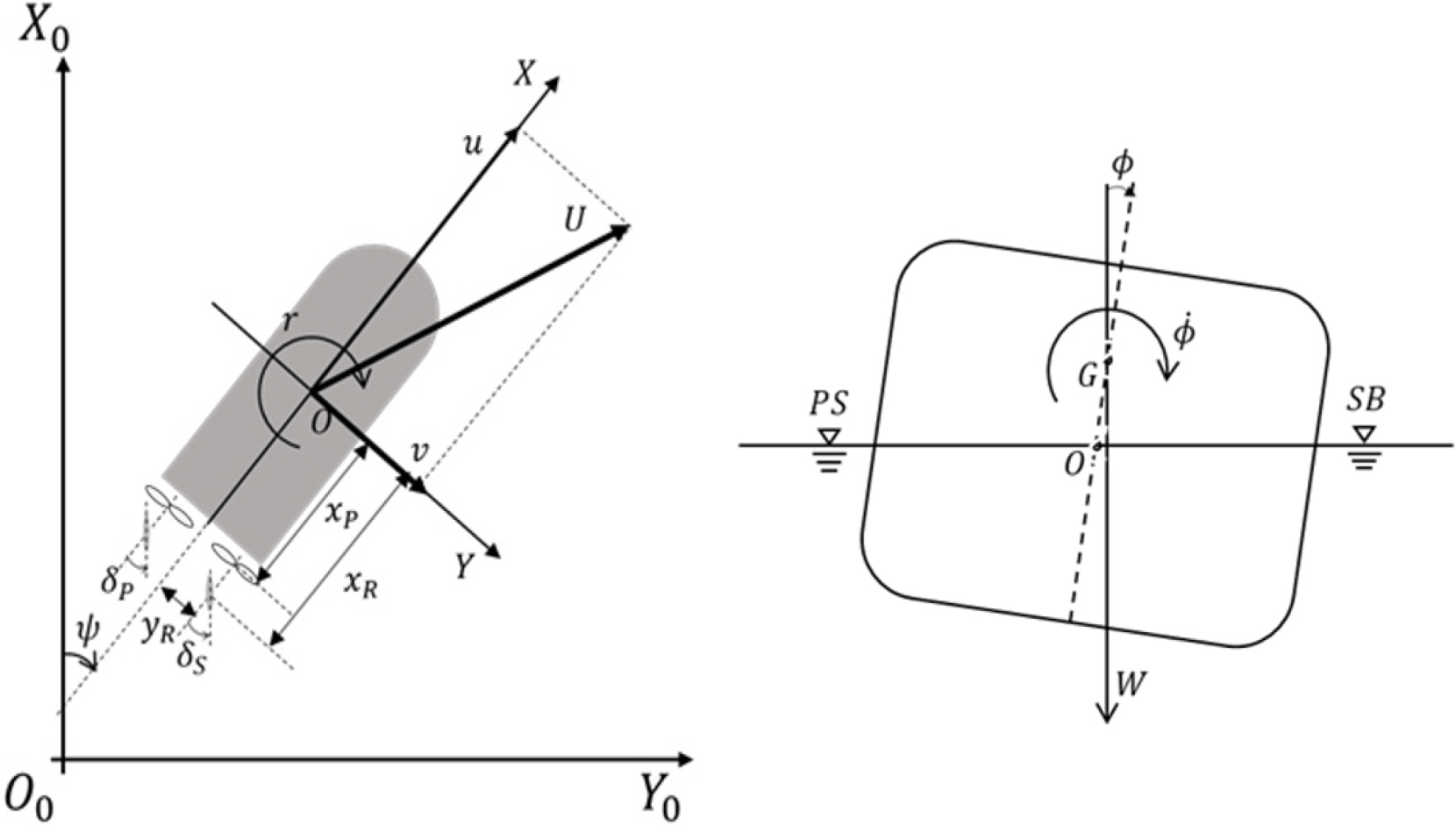
p: Roll rate of ship about x-axis

R0: Resistance of ship in longitudinal direction

r: Yaw rate of ship about z-axis

T: Ship draft

tP: Thrust deduction factor

tR, xH: Rudder–hull interaction coefficients

u: Surge velocity of ship in x direction

v: Sway velocity of ship in y direction

vR: Sway inflow velocity twin rudders

wP: Propeller wake fraction

Xu̇ Yv̇: Added mass

XH: Hull hydrodynamic force in x direction at midship

XP: Hydrodynamic force due to twin propellers acting on ship in x direction

XR: Hydrodynamic force due to twin rudders acting on ship in x direction

Xfin: Hydrodynamic force due to side fin acting on ship in x direction

YH: Hull hydrodynamic force in y direction at midship

YR: Hydrodynamic force due to twin rudders acting on ship in y direction

yP: Offset distance of rudder stock from the ship center line

zH: Vertical distance between the acting point of sway hydrodynamic force on hull and the origin of the body-fixed frame

zR: Vertical distance between the acting point of lift force on rudder and the origin of the body-fixed frame

β: Ship drift angle

βR: Geometrical drift angle induced at the rudder position due to ship motions

γR: Rudder flow-straightening coefficients for drift angle

δ: Rudder angle

δR: Effective rudder angle where the rudder normal force becomes zero

∊: Ratio of effective wake fraction in way of propeller and rudder

κ: An experimental constant for expressing

ρ: Water density

ϕ: Roll angle of ship

1. Introduction

An accurate estimation of maneuverability is required when designing a ship. Particularly, studies on the estimation of maneuverability are actively being conducted owing to the recent surge of interest in marine accidents and pollution, and its importance is arising to more accurately simulate the movement trajectory and operating condition of a ship involved in an accident (Yun and Yeo, 2019). Generally, the maneuverability is expressed in 3-DOF (degree of freedom) coupling motion on the water level because the motion response frequency of the ship caused by the steering or speed change is low, and other motion components can be neglected. However, as ships become larger and faster, it is noted that large container ships with low metacenter heights and warships operating at high speeds generate a relatively large amount of roll to a degree where such effect cannot be ignored (Sohn and Kim, 2003).
The methods for estimating the maneuverability performance of ships can be divided into system-based and direct analyses methods. Studies on the estimation of maneuverability performance using a system-based analysis method have been continuously conducted. Yasukawa and Yoshimura (2015) derived the hydrodynamic derivative using captive model tests and virtual captive model simulations. Maneuvering motion simulation was performed to predict maneuverability and veering performance based on a 3-DOF maneuvering motion equation and the maneuvering mathematical group (MMG) model. In the study by Sukas et al. (2019), the hydrodynamic derivative of a twin-axle ship was derived through computational fluid dynamics (CFD), and the maneuvering performance was estimated based on the 3-DOF MMG mathematical model. In general, studies on estimating steering performance considering only 3-DOF (surge, sway, yaw) have been conducted, but considering roll, research on the estimation of maneuvering performance based on 4-DOF (surge, sway, roll, yaw) is now being conducted. Yasukawa et al. (2019) derived the hydrodynamic derivative and vertical action point related to roll motion using a simple empirical formula based on experimental data on four types of ships in the existing 3-DOF MMG mathematical model, and resulting in 4-DOF MMG mathematical model. Furthermore, a maneuvering motion simulation was performed to study the effect of roll on the maneuvering performance while altering the GM. In addition, a study was conducted to examine the change in turning ability, by controlling the sway through an active fin attached to the rudder or ship side (Zhao et al., 2019; Lihua et al., 2019). Several studies prove that the turning ability improves when the heel angle in the outward direction of the turn occurs and the veering performance deteriorates.
As described above, studies on the estimation of maneuvering performance using the existing system-based analysis method generally adopted 3-DOF. However, a 4-DOF (surge, sway, roll, and yaw) MMG mathematical model was utilized in this study to improve the accuracy of estimating the maneuvering performance of a David Taylor Model Basin 5415 (DTMB 5415) ship model operating at high speed. A study was conducted on the change of turning performance according to the ship’s speed and side fin angle. In the MMG model of the previous study, the lift and drag forces generated from the side fin are calculated using the lift coefficient of the cross-sectional shape of the wing. However, it is necessary to consider the three-dimensional shape of the wing, submergence, and interference with the hull to accurately calculate the lift and drag generated by the fin. This study first built a maneuvering motion simulation model based on the 4-DOF MMG mathematical model. The lift, drag, and moment generated by the side fin were considered as the external force term. Furthermore, the lift and drag forces generated from the side fin during ship operation were more accurately calculated utilizing a constructed DTMB 5415 CFD model. The result was used as the external force term. In addition, a 35° turning simulation was performed using a 4-DOF MMG maneuvering motion simulation model, which was verified by comparing the results with the model latetest results. Finally, a 35° turning simulation was performed by changing the fin’s angle on the side of the DTMB 5415. Accordingly, it was confirmed that the MMG simulation model constructed using the lift and drag of the fin calculated through CFD could estimate the maneuverability to a high degree. It was also determined that the heel angle changed when the ship steadily rotated according to the fin angle and the turning performance changed accordingly.

2. 4-DOF Maneuvering Motion Equation

2.1 Coordinate System

In this study, as shown in Fig. 1, an Earth-fixed coordinate system set to an arbitrary point on the Earth and a hull-fixed coordinate system set to the hull’s center were used. O0X0Y0Z0 represents the Earth’s fixed coordinate system, and the horizontal plane is defined as an X0Y0 plane. The hull-fixed coordinate system is represented by OXYZ, X-axis is defined as the bow direction, Y-axis is defined as the starboard direction, and positive direction of both Z0,Z coordinate systems is defined as the direction of the bottom of the hull.

2.2 Mathematical Model of the Maneuvering Motion

In this study, surge, sway, roll, and yaw’s 4-DOF equations of motion are adopted. If the motion of the hull is described based on the fixed hull coordinate system and center of the hull, it can be expressed as Eq. (1). In Eq. (1)m, mx, my represent the ship’s mass and additional mass in the x and y directions, respectively. Ix, Iz and Jx, Jz are moments of inertia and additional inertia moments of the x and z axes, respectively. u, v, p, r are the velocities in each direction, and the dot on the velocity denotes acceleration component in each direction. X, Y, K, N on the right side represent the forces and moments in each direction, and the subscripts H, R, P and F represent the hull, rudder, propeller, and fins, respectively. In addition, the relationship between the angular velocity between the Earth-fixed and hull fixed coordinate systems is expressed as Eq. (2).
(1)
(m+mu)u˙-(m+my)vmr-mxGr2+mzGpr=XH+XP+XR+Xf(m+my)v˙m+(m+mx)ur+(mxG=Yr˙)r˙-mzGp˙=YH+YR(Iz+Jz)r˙+(mxG-Nv˙)v˙+mxGur=NH+NP+NR+Nf(Ix+Jx)p˙-(mzG+Kv˙)v˙-Kr˙r˙-Kϕ˙ϕ˙-mzGur=KH+KR+Kf
(2)
ψ˙=rcosϕϕ˙=p
The force applied to the hull is expressed in Eq. (3), and nondimensionalization is applied through the density of the fluid, hull length, draft, and ship’s speed as in Eq. (4). Following the purpose of this study, hydrodynamic derivatives including the roll and coupling effect of the roll with other 3-DOF movement, are included when calculating the hydrodynamic force applied to the hull. The hydrodynamic derivatives adopted above is presented in Table 1.
(3)
XH'(vm',r,ϕ)=-R0'+Xvv'v'2+Xrr'r'2+Xϕϕ'ϕ'2YH'(vm',r,ϕ)=Yv'v+Yr'r+Yvvv'v'3+Yrrr'r'3+Yvvr'v'2r+Yvrr'vr'2+Yϕ'ϕ+Yϕϕϕ'ϕ'3+Yvvϕ'v'2ϕ+Yvϕϕ'vϕ'2+Yrrϕ'r'2ϕ+Yrϕϕ'rϕ'2NH'(vm',r,ϕ)=Nv'v+Nr'r+Nvvv'v'3+Nrrr'r'3+Nvvr'v'2r+Nvrr'vr'2+Nϕ'ϕ+Nϕϕϕ'ϕ'3+Nvvϕ'v'2ϕ+Nvϕϕ'vϕ'2+Nrrϕ'r'2ϕ+Nrϕϕ'rϕ'2KH'(vm',r,ϕ)=-(mgGZ¯)=(zHYH(v,r))+Kϕ'ϕ+Kϕϕϕ'ϕ'3+Kvvϕ'v'2ϕ+Kvϕϕ'vϕ'2+Krrϕ'r'2ϕ+Krϕϕ'rϕ'2
(4)
XH=1/2ρLPPdU2XH'(vm',r,ϕ)YH=1/2ρLPPdU2YH'(vm',r,ϕ)NH=1/2ρLPPdU2NH'(vm',r,ϕ)KH=1/2ρLPPdU2KH'(vm',r,ϕ)
The hydrodynamic caused by the propeller rotation is expressed as Eq. (5). Because the lateral force or moment due to rotation is small, the sway force and sway moment are generally negligible. In addition, the target ship used in this study is a twin-axle, and the left and right propeller shafts are separated from the lateral center of the ship. Therefore, a moment occurs because it acts as a moment arm. The hydrodynamic force generated during steering is expressed as Eq. (6). Equation (7) expresses the force generated by the flow field in which the longitudinal flow of the hull accelerated past the propeller plane and the lateral flow generated at other positions by yaw are added. The coefficients related to propeller and rudder are presented in Table 2.
(5)
XP=ρ((1-tP{S})nP{S}2DP{S}4KT{S}-(1-tP{P})nP{P}2DP{P}4KT{P})NP=yP{S}ρ((1-tP{S})nP{S}2DP{S}4KT{S}(1-tP{P})nP{P}2DP{P}4KT{P})
(6)
XR=-(1-tR{SP}(FyR{S}sinδ+FxR{S}cosδ+FyR{P}sinδ+FxR{P}cosδ)YR=-(1-aH(FyR{S}cosδ+FxR{S}sinδ+FyR{P}cosδFxR{P}sinδ)NR=-(xR+aHxH)(FyR{S}cosδ-FxR{S}sinδ+FyR{P}cosδ-FxR{P}sinδ)+(1-tR{SR})yR{S}(FyR{S}sinδ+FxR{S}cosδ-FyR{P}sinδ-FxR{P}cosδ)KR=-zRYR
(7)
UR{SP}=uR{SP}2+vR{SP}2uR{SP}={SP}uP{SP}ηP{SP}{1+κ(1+8KT{SP}πJP{SP}2-1)}2+1-ηP{SP}vR{SR}=uR{SP}tanδR{SR}δR{SR}=γR{SR}βR{SR}-tan-1(yR{SP}xR{SP})
The hydrodynamic force caused by the side fin is expressed as Eq. (8). The side fin is a wing-shaped lifting body that generates lift, drag, yaw moment, and roll moment at the left and right sides of the hull. The process of deriving Dfin and Lfin expressed on the right side of Eq. (8) is described in Section 3.
(8)
Xf=DfinYf=0Nf=Df×FCGKf=Lf×FCG

3. Numerical Analysis of the Side Fin Lift and Drag

3.1 Target Ship

In this study, DTMB 5415 (SIMMAN, 2014) was selected as the target ship, and numerical analysis was performed on a 1:35.48 scale. The DTMB 5415 operates at a high speed, causes a comparably large roll, and is relatively easy to control the roll because it is equipped with side fins. The shape and main specifications of DTMB 5415 are presented in Fig. 2 and Table 3.

3.2 Numerical Analysis Conditions

The commercial CFD software STAR-CCM+ ver. 15.06 was used in this study. The numerical analysis is set as Fig. 3 to satisfy the calculation area suggested by the International Towing Tank Conference’s (ITTC) recommended procedures and guidelines (ITTC Resistance Committee, 2017), i.e., 1.5 times the hull length in the bow direction from the center of the hull, 2.5 times the hull length in the stern direction, 1.5 times the hull length in the port and starboard directions, respectively, 1.5 times the hull length in the bottom direction, and 0.5 times the hull length in the deck direction area were set.
Trimmer mesh and prism layer techniques provided by STAR-CCM+ were used to generate the grid. The grid size and configuration were altered using the trimmer technique according to the disturbance characteristics of the flow by the hull. The grid size was designated relatively small around the free surface and the hull, and the grid size was designated relatively large in areas judged to be a relatively simple flow. The boundary layer grid was used to calculate the boundary layer flow on the hull surface. In addition, the Dynamic Fluid Body Interaction (DFBI) technique was applied to consider the movement of the ship, and the sliding mesh technique was employed to implement the rotational motion of the side fin. The completed example of the grid system is shown in Fig. 4, and the total number of the grids is approximately 2.36M.
A volume of fluid (VOF) model was used to implement the free surface, and the Realizable k− ϵ model was used for the stable and efficient numerical calculation of the turbulence model. As presented in Table 4, the boundary conditions of the numerical calculation are as follows: velocity inlet condition was designated to the inlet, top, bottom, and side boundaries, and a pressure outlet condition was designated to the outlet boundary, and infinite depth was configured. In addition, damping conditions were set at the inlet, outlet, and side boundaries to minimize disturbance due to the reflected waves.

3.3 Verification of the Numerical Analysis

A grid convergence test was performed on the generated grid system before performing numerical analysis on the lift and drag simulation. The grid convergence test was conducted using a resistance test at a ship speed corresponding to Fn = 0.25, according to the method suggested by the ITTC recommended procedures and guidelines, while the refinement ratio was set to 2 (Celik et al., 2008). As presented in Table 5, the grid system has four grid sizes: very fine, fine, medium, and coarse. The results for each grid system are shown in Fig. 5, and the convergence index is presented in Table 6.
The grid convergence study demonstrated that the resistance coefficient converges as the number of grids increases. In Table 7, the resistance results of each grid system are compared with the model test results of the Iowa Institute of Hydraulic Research (IIHR), and subsequent calculations were performed using Grid no. 3 with a fine grid size, considering the efficiency and convergence of the calculation time.

3.4 Simulation of the Side Fin Lift and Drag

Lift and drag simulations were performed to derive a mathematical model for the hydrodynamic force generated by the side fin. In order to check the effect of interference with the hull and submerged depth that occurs when the fin is attached to the ship, lift and drag force were calculated when the fin is alone and attached to the ship as shown in Fig. 6. The angle of attack range of the lift and drag simulations was −30° to 30° for each case and was performed at intervals of 5°.
The simulation results are shown in Fig. 7. The drag force did not indicate a significant difference between the case where the fin was attached to the hull and that where the fin was left alone. Although it appeared somewhat large when the fin was attached to the hull, it was judged that it was not a difference that would have a significant effect at each angle of attack. In the case of lift, however, there was a considerable difference in two cases. Regarding the fin alone, stall did not occur in the range of −30° – 30° and indicated symmetrical tendency at positive and negative angles of attack. However, the lift generated when the fin is attached to the hull causes stalling at a negative attack angle of approximately −25° and a positive attack angle of approximately 30°, and is moved in parallel in the positive direction as compared to the case where the fin is by itself.
(9)
CD=Drag0.5ρSfinU2CL=Lift0.5ρSfinU2
To analyze the cause of the difference in the lift, the flow and pressure distribution were compared. Fig. 8 illustrates the flow velocity when the angle of attack is 0° in each case, while Fig. 9 illustrates the pressure distribution when the angle of attack is 0° in each case. Regarding the fin alone, it was confirmed that the flow velocity distribution in the areas above and below the fin was symmetrical because the airfoil of the fin was vertically symmetrical. However, when attached to the hull, the flow velocity around the fin was relatively accelerated compared to the case of the fin alone, and the flow velocity in the upper region of the fin was faster than the flow velocity in the direction of the bottom of the fin. Accordingly the dynamic pressure in the upper area of the fin was reduced, and when the fin was attached to the hull, it was determined that the lift was generated in the deck direction even when the attack angle was 0°. Such flow characteristic appears even when the angle of attack occurs. Accordingly, the lift is shifted in the positive direction, in parallel over the entire angle of attack section, compared to the case of the fin being left alone. In addition, when the fin was attached to the hull, a stall occurred at a smaller attack angle owing to interference with the hull. It is determined to be this way because when the fin is attached to the hull, the hull acts to block the flow; hence, the flow cannot escape by flowing on the hull, and this resulted in the generation of a vortex. and included in the mathematical model were derived based on the lift drag simulation results.

4. 35° Turn Simulation in Consideration of the Side Fin Attack Angle

4.1 Conditions on the Turning Simulation

A turning simulation was performed to confirm the change in turning performance due to lift, drag, and moment, generated by the change in the angle of attack of the side fin. In this case, several conditions are given to the angle of attack of the side fin. First, the maximum angle of the side fin followed the conditions provided in the study by Toxopeus et al. (2011). In this study, the maximum angle of the side fin is limited to δfin ≤25°. In addition, the direction of the side fin is defined in two ways. The direction in which the side fin inclines the hull in the port side is defined as a positive direction, and the direction in which the hull is inclined to the starboard side is defined as a negative direction. Table 8 below presents the angle of attack and the direction of the generated moment of the fin in each direction based on the conditions.

4.2 Turning Simulation Results According to the Changes in the Side Fin Angle of Attack

A 35° turning simulation was performed by changing the angle of attack according to the conditions of the fin on the side of the ship. The turning trajectory is compared in Fig. 10, and the motion information is shown in Fig. 11. In addition, Table 9 presents the turning ability index of each result.
As a result of the simulation by changing the side fin in the positive direction, the turning trajectory decreases as the angle of attack increases. As shown in (a) of Fig. 11, the angle of convergence during a steady turn increases in the outward direction of the turn as the angle of attack increases. According to Figs. 11 b and c, the ship speed decreases further as the angle of attack and turning angular velocity increases. As shown in Figs. 11 d and e, as a result of observing the speed in the surge and sway directions, the speed in the surge direction decreased more as the angle of attack increased, while there was insignificant change in the speed in the sway direction. When the side fin was at a maximum angle of 25°, the advance decreased by approximately 2.5%, the transfer decreased by approximately 5%, and the tactical diameter decreased by approximately 5%.
As a result of the simulation by changing the side fin in the negative direction, it can be observed that the turning trajectory decreases as the angle of attack increases. Fig. 11 illustrates that as the angle of attack increases, the angle of convergence during a steady turn decreases as it inclines toward the inside of the turn. According to Figs. 11 a and b, the ship speed and turning angular velocity decrease as the angle of attack increases. As observed in Figs. 11 d and e, if the speed is divided into the surge and sway directions, the ship’s speed in the surge direction decreases further as the angle of attack increases. The ship’s speed in the sway direction also decreases. When the side fin was at a maximum angle of −25°, the advance decreased by approximately 1.4%, the transfer by 3%, and the tactical diameter by 2.7%.
The opposite trend to the previous studies is indicated in the case of the side fin having a negative direction when compared with the results of previous studies on the roll effect of the maneuvering performance of a ship. As the angle of attack increased, the heel angle in the inward direction of the turn increased, and the turning angular velocity decreased. However, when considering the change in the ship speed, the change in the speed in the sway direction occurred, unlike the case where the side fin has a positive direction. During the turn, the ship speed in the sway direction occurred in the outward direction of the turn, and the ship speed decreased as the angle of attack increased while the side fin has a negative sign. It is determined that the turning circle decreased as the speed toward the outside of the turn decreased, although the heel angle increased in the inward direction of the turn.

5. Discussion

This study aimed to improve the degree of estimation of the ship’s maneuverability using a 4-DOF motion equation and mathematical model considering roll motion and to check the change in turning performance according to the angle of attack of the side fin attached to the hull of the DTMB 5415. The lift and drag force were calculated using the CFD model of DTMB 5415 hull with an attached fin to consider the effects of the submerged depth, interference with the hull, and three-dimensional shape of the fin. Considering this effect, a mathematical model for the side fin was derived using the CFD calculation results. A 4-DOF maneuvering simulation model was constructed based on the derived mathematical model, and a 35° turning simulation was performed using the constructed simulation model. As a result of the simulation, the following conclusions were drawn.
When the fin was attached to the side of the hull, various influences caused a change in the lift and drag, and when it was alone, a lift occurred in the direction of the deck. Based on these results, a 4-DOF maneuvering simulation model considering roll was constructed to perform a turning simulation. Accordingly, the degree of estimation of the ship’s maneuverability was improved. In addition, the change in the turning performance was confirmed based on the change in the angle of attack of the side fin. When the side fin had a positive sign, the heel angle in the outward direction of the turning increased as the angle of attack increased, turning angular velocity increased, and turning performance was improved. Turning performance was also improved when the side fin had a negative sign. It is determined that the turning circle decreased as the ship’s speed in the sway direction toward the outside of the turn decreased, although the angular velocity of the turn decreased owing to the heel angle occurring in the inward direction of the turn. This signifies that the reduction of the sway direction toward the outward of the turn can also affect the turning performance in addition to the heel angle in the inward direction.
As a result of this study, it was possible to improve the turning ability of a high-speed twin-axle ship using two methods. Depending on the turning direction of the ship, by increasing the heel angle in the outward direction of the turn, the turning angular velocity may increase, thereby improving the turning performance. In addition, it was proven that the turning performance could be improved by increasing the heel angle in the inward direction of the turn and decreasing the ship’s speed in the sway direction with the drag and moment of the side fin.

Conflict of Interest

No potential conflict of interest relevant to this article was reported.

Funding

This study is the result of research conducted with the support of the Korea Institute for Advancement of Technology (KIAT) with the funding of the Ministry of Trade, Industry and Energy’s “Industrial Professionals Competency Reinforcement Project” Basic research project (No. 2020R1F1A1071610) supported by the National Research Foundation with funding from the Ministry of Communications) and CO2 (DFOC) reduction based on the real operation of medium-sized ships conducted with the funding of the Ministry of Trade, the Industry and Energy’s “Medium Shipyard Innovation Growth Development Project” with the support of Technology Development (Project No.: 20007847), and research project of Inha University (Project No.: 62968).

Fig. 1.
Coordinate systems of maneuvering motion
ksoe-2021-099f1.jpg
Fig. 2.
DTMB 5415 hull model (w/full appendage)
ksoe-2021-099f2.jpg
Fig. 3.
Computational domain
ksoe-2021-099f3.jpg
Fig. 4.
Surface and volumetric mesh
ksoe-2021-099f4.jpg
Fig. 5.
Results of grid convergence test
ksoe-2021-099f5.jpg
Fig. 6.
Lift and drag simulation target fin model
ksoe-2021-099f6.jpg
Fig. 7.
Lift and drag simulation results
ksoe-2021-099f7.jpg
Fig. 8.
Velocity contour around side fin
ksoe-2021-099f8.jpg
Fig. 9.
Dynamic pressure contour around side fin
ksoe-2021-099f9.jpg
Fig. 10.
Comparison of turning trajectory
ksoe-2021-099f10.jpg
Fig. 11.
Ship motion information during turning maneuver
ksoe-2021-099f11.jpg
Table 1.
Hydrodynamic derivatives
Item Value Item Value Item Value
R0' 1.6550.E-02 Yvvϕ' 1.3927.E+00 Nvϕϕ' 2.1091.E+00
Xvv' −5.8910.E-02 Yvϕϕ' −2.4552.E+00 Nrrϕ' 7.6866.E-04
Xrr' −1.4561.E-02 Yrrϕ' 6.4651.E-02 Nrϕϕ' 3.8422.E-01
Xϕϕ' −2.2055.E-02 Yrϕϕ' −1.7005.E+00 Kϕ' −5.8993.E-04
Xvr' 6.5426.E-03 Nv' −1.1671.E-01 Kϕϕϕ' 2.3286.E-02
Yv' −3.6663.E-01 Nvvv' −5.1760.E-01 Kvvϕ' −1.7666.E-02
Yvvv' −2.0415.E+00 Nr' −8.2431.E-02 Kvϕϕ' 3.6785.E-01
Yr' 3.7452.E-02 Nrrr' −8.3312.E-03 Yv˙' −1.1576.E-01
Yrrr' −1.0412.E-02 Nϕ' −1.0234.E-04 Nv˙' −1.5494.E-02
Yϕ' −2.0169.E-02 Nϕϕϕ' −4.2441.E-02 Yr˙' −9.8130.E-03
Yϕϕϕ' −1.2014.E-01 Nvvr' −1.5637.E+00 Nr˙' −1.0008.E-02
Yvvr' −8.2264.E-01 Nvrr' −5.3745.E-01 Kp' −2.6600.E-04
Yvrr' −3.6761.E-01 Nvvϕ' −5.8824.E-01 zH' 2.2100.E-02

Hydrodynamic derivatives are adopted from Dash et al. (2015)

Table 2.
Coefficients related to propeller and rudder
Item Value Item Value
tP0 0.15 zR' 0.035
ωP0 0.05 0.925
τβP −0.108 κ 0.59
τ3βP −0.5 lR' −0.9436
λβP −0.267 tR 0.4404
λ3βP −1.625 For βR<0° γR{S} 0.5317
aH 0.063 γR{P} 0.3713
xH' −0.391

Coefficients are adopted from Dash et al. (2015) and Sukas et al. (2019)

Table 3.
Principal properties of a DIMB 5415
Properties Ship Model
1 35.48
LPP(m) 142 4.002
B(m) 19.06 0.537
T(m) 6.15 0.173
Hull LCG(m) 71.6 2.018
VCG(m) 1.39 0.039
Disp.(m3) 8425 0.189
CB 0.507
Fn 0.248
Table 4.
Boundary condition
Boundary Boundary condition
Inlet, Side, Top, Bottom Velocity inlet
Outlet Pressure outlet
Ship Wall
Table 5.
Grid type of convergence test
Grid no. Grid density Number of cells
1 Coarse 0.52 M
2 Medium 1.04 M
3 Fine 2.36 M
4 Very fine 5.68 M
Table 6.
Grid convergence index
12 32 43 (%)
Resistance coefficient 1.36E-01 5.80E-02 7.00E-03 0.02
Table 7.
Comparison of Resistance with EFD
Grid no. 1 Grid no. 2 Grid no. 3 Grid no. 4 IIHR EFD
CTM(×103) 4.398 4.262 4.204 4.197 4.070
Diff. about EFD (%) 8.06 4.71 3.28 3.12 -

IIHR EFD result are adopted from Olivieri et al. (2001)

Table 8.
Condition of side fin
Side fin direction Roll moment Side fin’s angle of attack
Positive Port side Starboard side 10°, 20°, 25°
direction moment Port side − 10°, − 20°, − 25°
Negative Starboard side Starboard side − 10°, − 20°, − 25°
direction moment Port side 10°, 20°, 25°
Table 9.
Turning performance index
Fin angle Advance (m) Transfer (m) Tactical Dia. (m)
25° 3.087 (−2.57%) 1.682 (−5.13%) 3.976 (−5.03%)
20° 3.115 (−1.68%) 1.710 (−3.57%) 4.054 (−3.16%)
10° 3.152 (−0.50%) 1.743 (−1.68%) 4.154 (−0.79%)
3.168 1.773 4.187
−10° 3.167 (−0.02%) 1.764 (0.49%) 4.186 (0.01%)
−20° 3.146 (−0.70%) 1.751 (−1.27%) 4.125 (1.47%)
−25° 3.123 (−1.41%) 1.720 (−3.00%) 4.072 (2.73%)

References

Celik, IB., Ghia, U., Roache, PJ., Freitas, CJ., Coleman, H., & Raad, PE. (2008). Procedure for Estimation and Reporting of Uncertainty Due to Discretization in CFD Applications. Journal of Fluids Engineering, Transactions of the ASME, 130(7), 0780011-0780014. https://doi.org/10.1115/1.2960953
crossref
Dash, AK., Nagarajan, V., & Sha, OP. (2015). Uncertainty Assessment for Ship Maneuvering Mathematical Model. International Shipbuilding Progress, 62(1–2), 57-111. https://doi.org/10.3233/ISP-150117
crossref
ITTC Resistance Committee. (2017). Uncertainty Analysis in CFD Verification and Validation Methodology and Procedures. ITTC - Recommended Procedures and Guidelines, 1-13.

Lihua, L., Peng, Z., Songtao, Z., & Jia, Y. (2019). Simulation Analysis of Fin Stabilizers on Turning Circle Control During Ship Turns. Ocean Engineering, 173, 174-182. https://doi.org/10.1016/j.oceaneng.2018.12.067
crossref
Olivieri, A., Pistani, F., Avanzini, A., Stern, F., & Penna, R. (2001). Towing Tank Experiments of Resistance, Sinkage and Trim, Boundary Layer, Wake, and Free Surface Flow Around a Naval Combatant INSEAN 2340 Model. Security, 421, 1-42.

SIMMAN. (2014). Preprints of Workshop Proceeding. SIMMAN 2014, Copenhagen.

Sohn, K., & Kim, Y. (2003). A Study on New Mathematical Model of Ship Manoeuvring Motion Taking Coupling Effect of Roll into Consideration. In Journal of Korean Navigation and Port Research, 27(5), 451-458 https://doi.org/10.5394/KINPR.2003.27.5.451.
crossref
Sukas, OF., Kinaci, OK., & Bal, S. (2019). System-Based Prediction of Maneuvering Performance of Twin-Propeller and Twin-Rudder Ship Using a Modular Mathematical Model. Applied Ocean Research, 84, 145-162. https://doi.org/10.1016/j.apor.2019.01.008
crossref
Toxopeus, S., van Walree, F., & Hallmann, R. (2011). Manoeuvring and Seakeeping Tests for 5415M. AVT-189 Specialists’ Meeting on Assessment of Stability and Control Prediction Methods for NATO Air and Sea Vehicles. Portsdown-West, UK.

Yasukawa, H., Sakuno, R., & Yoshimura, Y. (2019). Practical Maneuvering Simulation Method of Ships Considering the Roll-Coupling Effect. Journal of Marine Science and Technology (Japan), 24(4), 1280-1296. https://doi.org/10.1007/s00773-019-00625-4
crossref pdf
Yasukawa, H., & Yoshimura, Y. (2015). Introduction of MMG Standard Method for Ship Maneuvering Predictions. Journal of Marine Science and Technology (Japan), 20(1), 37-52. https://doi.org/10.1007/s00773-014-0293-y
crossref pdf
Yun, K., & Yeo, DJ. (2019). An Experimental Study on the Manoeuvrability of a Ship in Heeled Condition. Journal of the Society of Naval Architects of Korea, 56(3), 273-280. https://doi.org/10.3744/SNAK.2019.56.3.273
crossref
Zhao, P., Liang, L., Zhang, S., Ji, M., & Yuan, J. (2019). Simulation Analysis of Rudder Roll Stabilization During Ship Turning Motion. Ocean Engineering, 189, 106322. https://doi.org/10.1016/j.oceaneng.2019.106322
crossref


ABOUT
BROWSE ARTICLES
ARTICLE CATEGORY

Browse all articles >

PUBLICATION ETHICS
FOR CONTRIBUTORS
Editorial Office
President Office BD Rm. 1302, 13 Jungang-daero 180beon-gil, Dong-gu, Busan 48821, Republic of Korea
Tel: +82-51-759-0656    Fax: +82-51-759-0656    E-mail: ksoehj@ksoe.or.kr                

Copyright © 2024 by The Korean Society of Ocean Engineers.

Developed in M2PI

Close layer
prev next