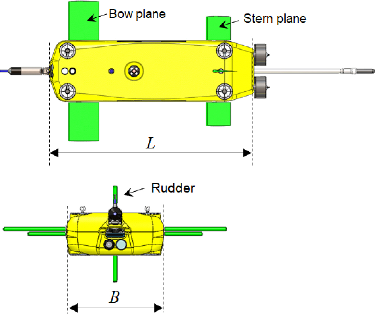
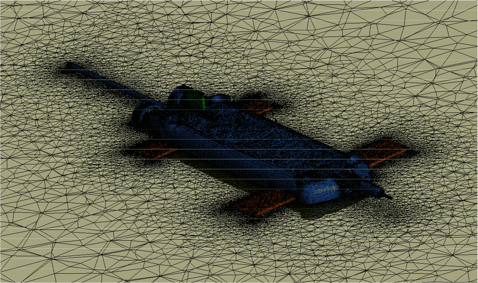
3.1 Static Test
A static test estimates damping coefficients by calculating the damping force contributing to the speed of the hull and the rotation of a control plane, and it comprises resistance, static drift, static angle of attack, combined, static rudder, and static elevator tests. Details on the hydrodynamic force model of each test are presented in
Table 4. The hydrodynamic force model was divided into two: a linear model in which the linearization of the force is possible because the size of perturbed state variables is small and a nonlinear model considering the nonlinearity of the force generated as motions become greater.
The results of the resistance test for estimating resistance per speed are presented in
Fig. 4. When neutral buoyancy is assumed as the force proportional to the square of the advanced speed, approximately 9.8% of dead weight is assumed to be applied in the design speed. Here, dead weight refers to the product of the acceleration of gravity and the mass of the submerged body. Resistance is proportional to the square of the advanced speed, and the resistance applied on the hull can be linearized if the change in the speed is negligible, based on a design speed of 2.57 m/s (5 knots). Accordingly,
Fig. 4 presents the results of the curve approximation of both linear and nonlinear models.
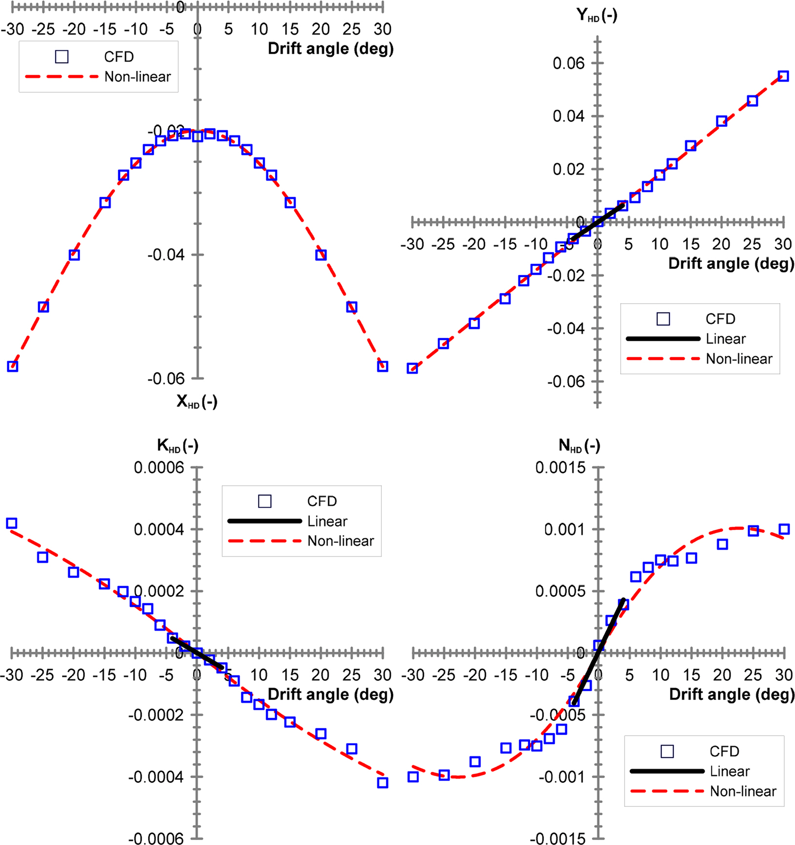
A static drift test calculates the damping force applied when only the sway velocity is generated; the results obtained from calculating the force by adjusting the drift angle by ±30° are presented in
Fig. 5. Nondimensionalization complies with the prime system 1 defined by the Society of Naval Architecture and Marine Engineering (SNAME) (
Fossen, 2011). The hydrodynamic forces were modeled according to the tendency of forces. The nonlinear model presented in
Table 3 was considered appropriate, and the coefficient of determination
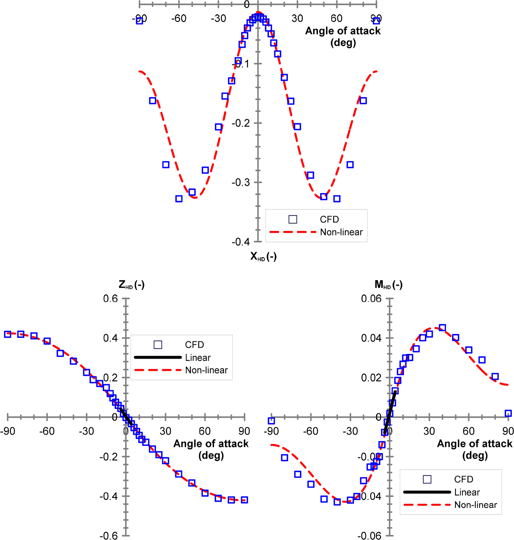
R2 was approximately 1. In addition, linear coefficients were identified within the drift angle range of ±4°. As previously mentioned, hydrodynamic forces were calculated by adjusting the angle of attack by up to ±90°, considering a large angle of attack; the results obtained from the static angle of attack test are presented in
Fig. 6. A stall occurs at approximately ±50° and ±40° of the surge and pitch, respectively, and the tendency of forces should be modeled using the same model as the static drift test. Nonlinear coefficients constituting the nonlinear model must be analyzed using simple curve approximation results because physical implication is ambiguous. In contrast, linear coefficients comprising the linear model have a distinct physical implication, such that the effectiveness of numerical analysis results can be determined by examining the correlation among linear coefficients when there are no experimental results, as in this study.
Fig. 7 presents the points of damping force applications when the sway
v and heave
w velocities are generated based on the linear coefficients of stability
Yv,
Kv,
Nv,
Zw, and
Mw, identified via the static drift and static angle of attack tests.
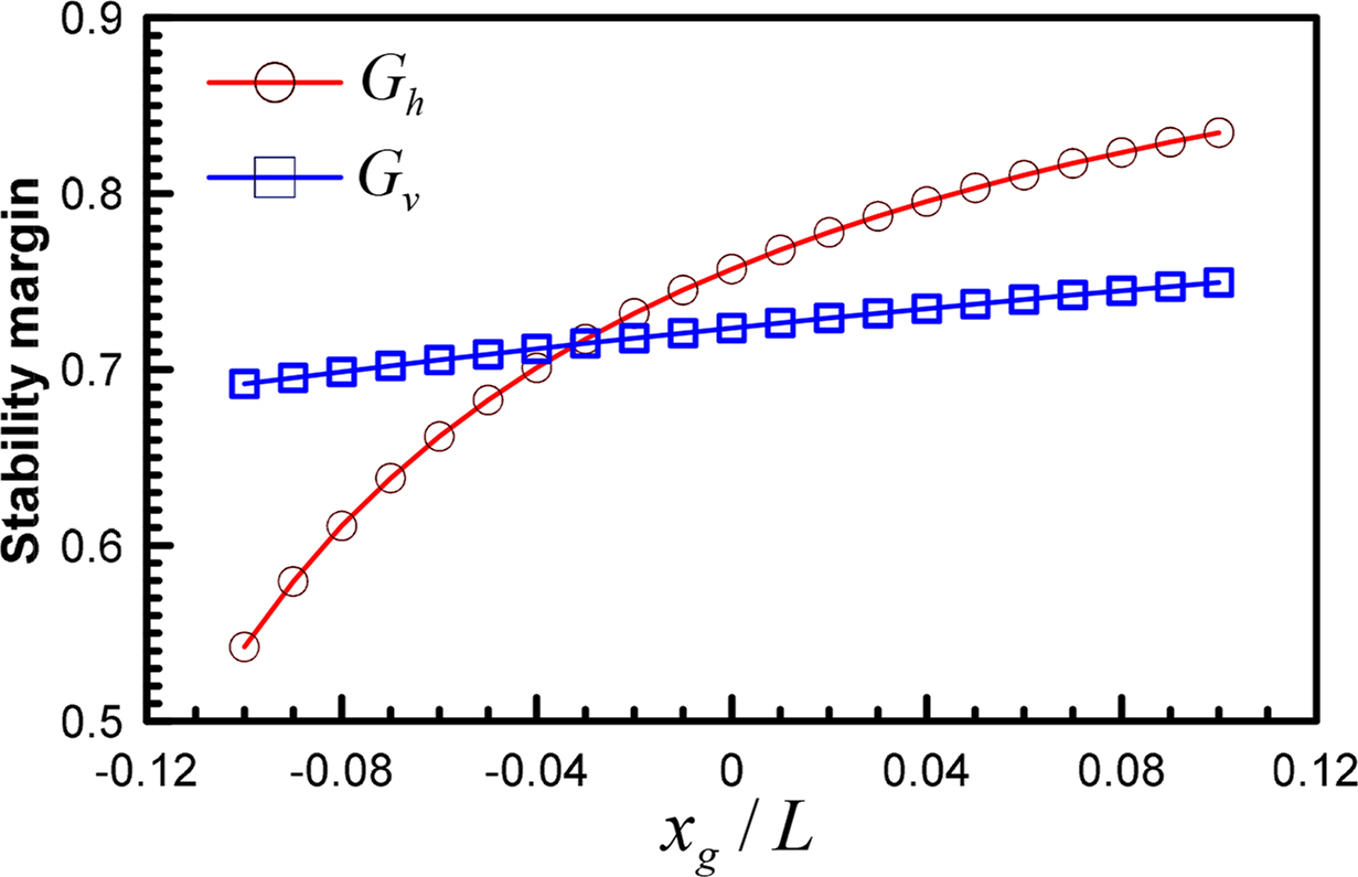
The side shape of the subject submerged body exhibits a tendency in which the rear part area is predominant owing to the large rudder attached in the rear part; thus, it is predicted to exhibit relatively better results in terms of horizontal stability. Therefore, Nv/Yv, which is the application point of the damping force in the longitudinal direction due to the sway velocity, is positioned at approximately 0.066L in front of the origin. Considering that the Nv/Yv of a general slender-type vehicle such as a ship is approximately 0.25L, the application point of the damping force moved backward considerably, toward the rear. Because the vertical shape is almost symmetrical, the application point Kv/Yv of the damping force in the height direction is positioned slightly upward with respect to the geometrical origin; however, the size is negligible. In contrast, Mw/Zw, which is the application point of the damping force in the longitudinal direction due to the heave velocity, is positioned approximately 0.277L toward the rear, with respect to the origin. A large bow plane exists in the head part, which implies that it is disadvantageous in terms of vertical stability, owing to the predominant head part.
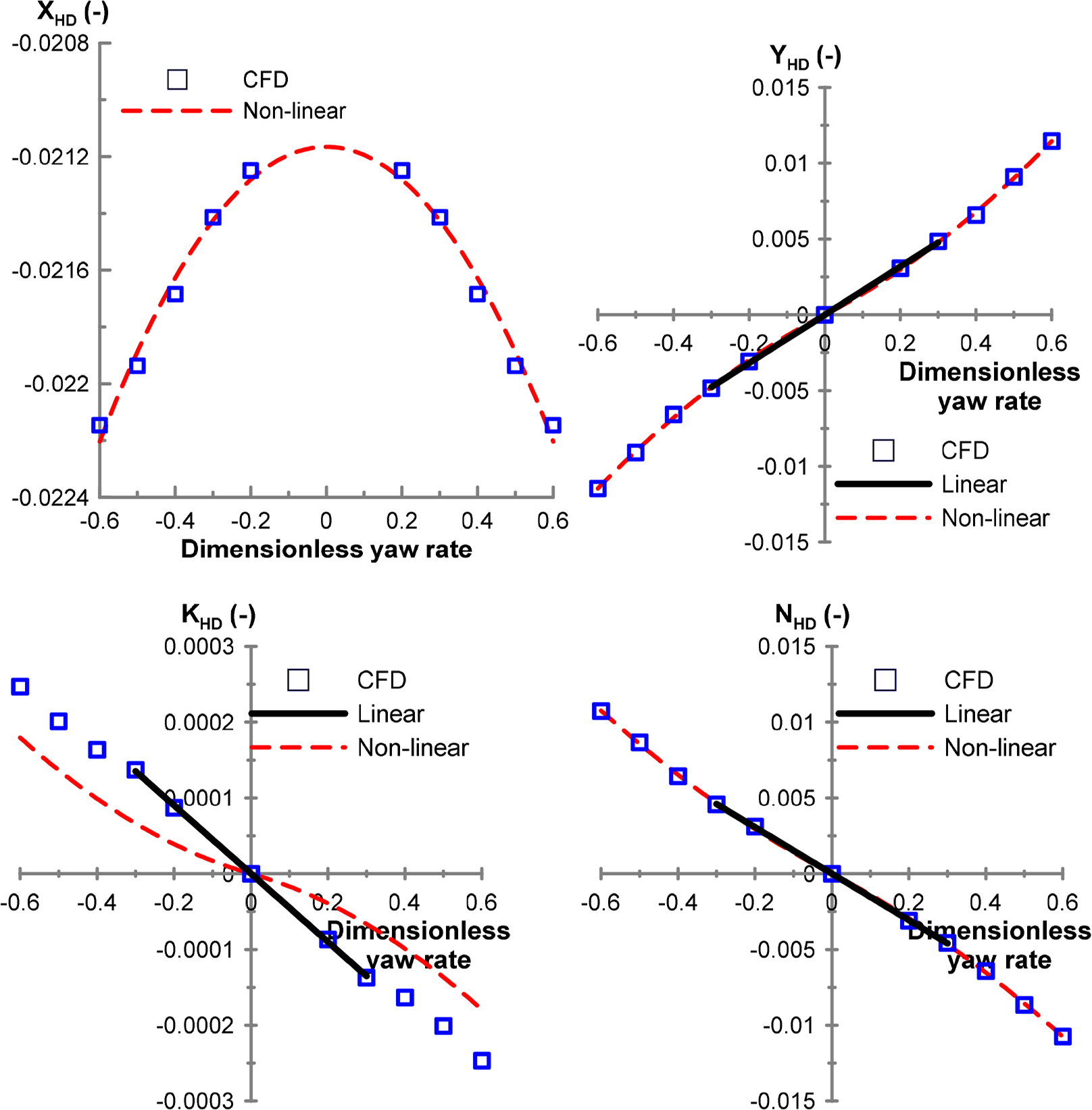
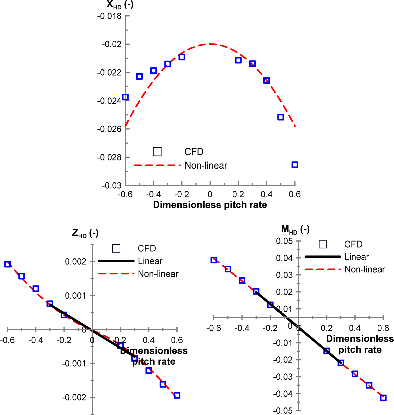
Figs. 8 and
9 present the results obtained from horizontal and vertical turning tests, which are conducted to determine the damping force and moment related to the yaw angular velocity
r and pitch velocity
q. The top area is more than two times greater than the side area of the hull, and the vertical hydrodynamic moment
MHD is substantially greater than the horizontal hydrodynamic moment
YHD. In contrast, hydrodynamic forces
YHD and
ZHD are the forces generated from the difference in the shapes of the head and rear parts during the rotational motions in which the asymmetry of the shapes of the head and rear parts significantly influence the horizontal hydrodynamic force
YHD .
Fig. 10 presents the results of a roll rotating test, which measures the force generated by a certain roll rate
p while a submerged body is advanced at speed
U . Generally, a submerged body with a cylindrical shape frequently experiences a large rolling motion if a controller is not applied because the roll damping coefficient applied on the hull is relatively small. The subject submerged body in this study has a relatively flat hull top surface and a large elevator area, thus exhibiting a large roll damping moment. As shown in
Fig. 10, which illustrates the roll damping moment
KHD for the roll rate
p, the order is greater than that of the same angular motion moment
NHD . A large roll damping moment indicates that a roll is not large during circular motions in which favorable dynamic characteristics can be obtained from the motion control perspective. A simulation must be conducted to verify whether such a phenomenon actually occurs.
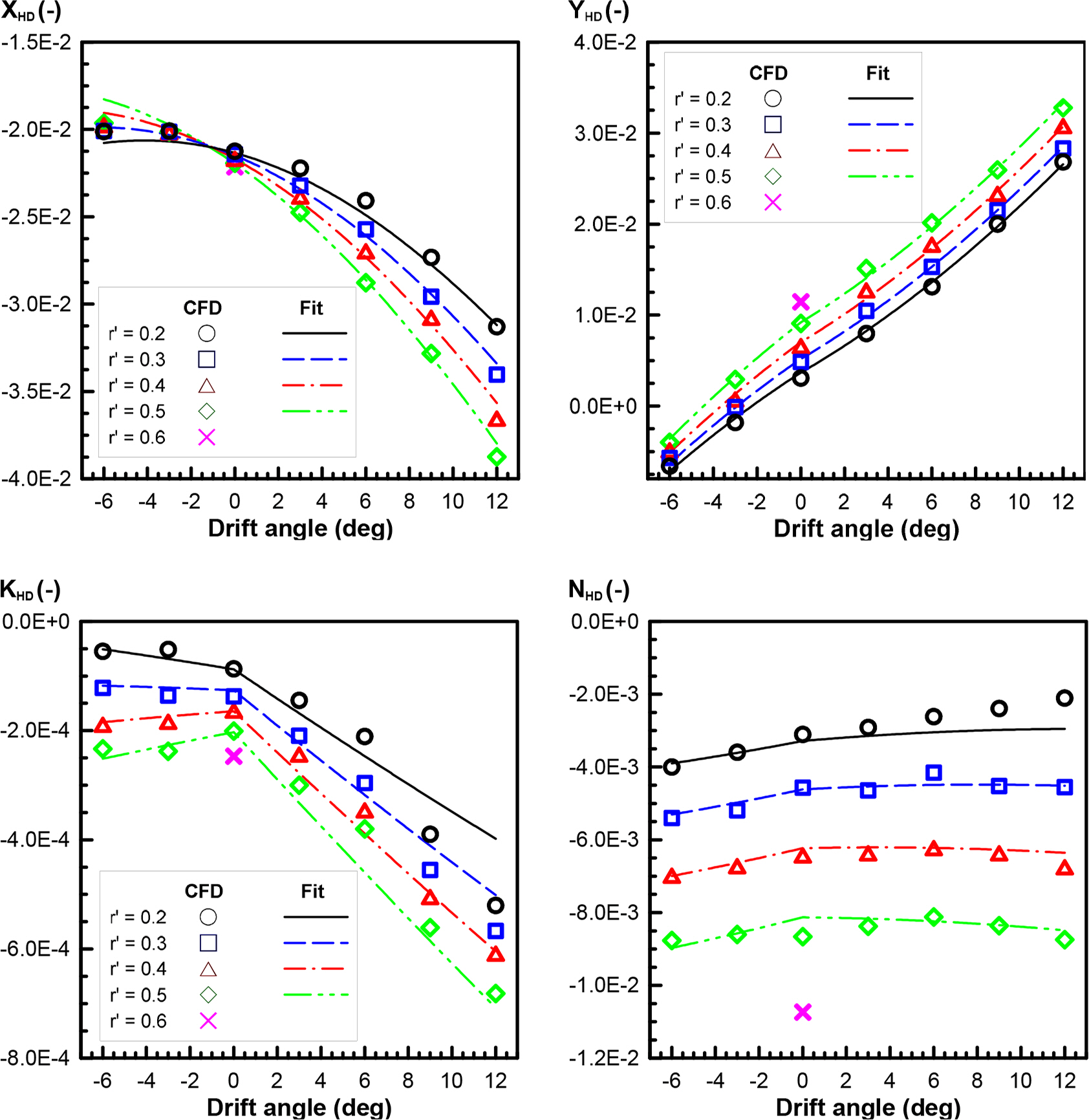
Figs. 11 and
12 present the results of the horizontal circular motion with the drift test and those of the vertical circular motion with the angle of attack test. The hydrodynamic forces measured in the static drift and horizontal turning tests are also measured when the horizontal circular motion with the drift test is performed; therefore, all hydrodynamic forces applied by and can be determined. Likewise, the hydrodynamic forces measured in the static angle of attack and vertical turning tests are also measured if the vertical circular motion is performed with drift test; therefore, all hydrodynamic forces applied by
w and
q can be determined.
All the damping coefficients due to ship motions
u,
v,
w,
p,
q, and
r were estimated via the above tests.
Table 5 presents the coefficient of determination of the hydrodynamic force model and corresponding models generated in the static rudder and static elevator tests.
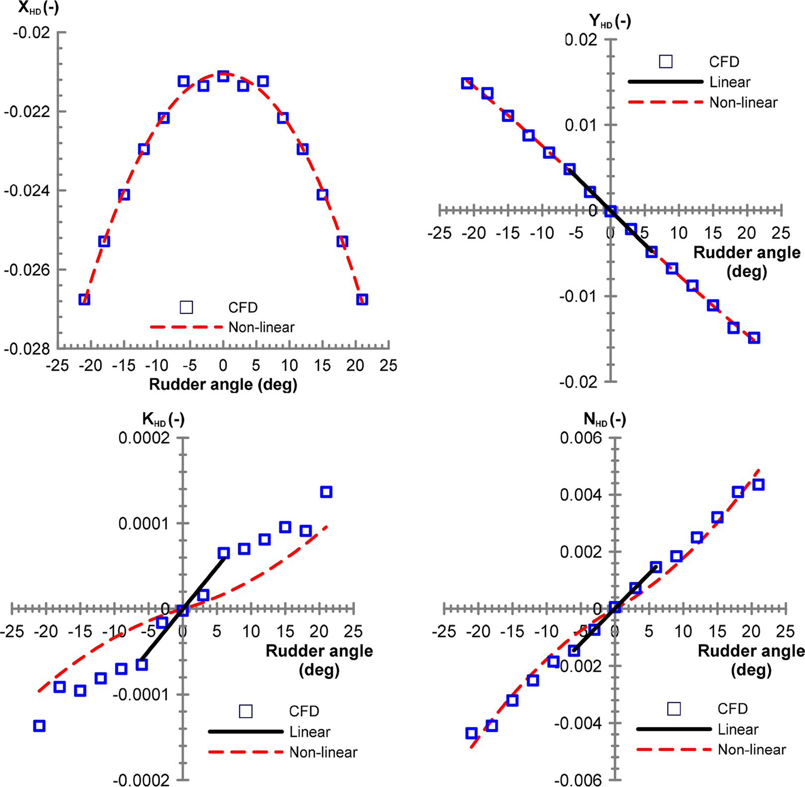
Figs. 13–
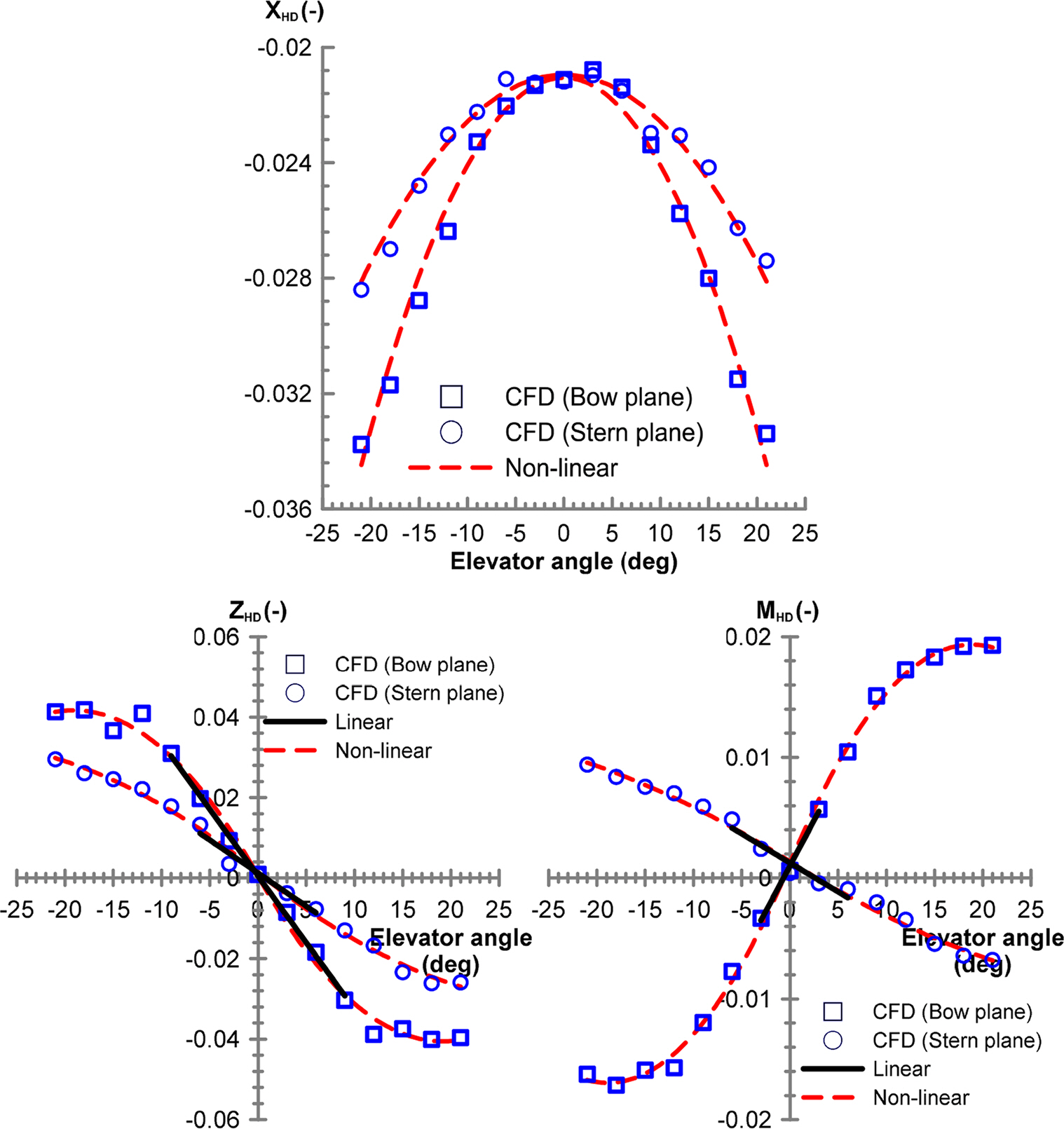
14 present the results of the static rudder and static elevator tests, respectively. In general, the center of pressure of the hydrodynamic forces applied on a rudder is positioned at approximately 1/4 the point of a rudder chord. Similar to the static drift test, hydrodynamic forces and the rudder angle have a linear relationship in a region with a small rudder angle; hence, a linear coefficient can be determined to estimate the center of pressure of the rudder force.
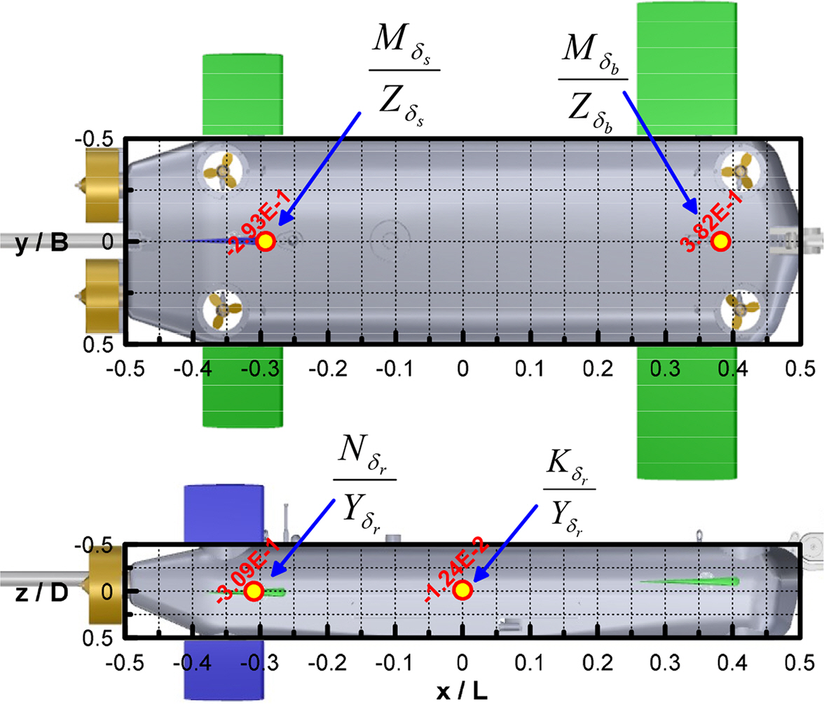
Fig. 15 presents the center of pressure on a rudder, which is estimated based on a linear coefficient when the rudder was rotated by a small angle. The center of pressure in the longitudinal direction
Nδr/
Yδr when the rudder was rotated is positioned closer to 1/4 of a rudder chord. The center of pressure in the vertical direction
Kδr/
Yδr is slightly more predominant in the top area from the side view of the hull; however, the size of
Kδr/
Yδr is negligible because the vertical shape of the hull is almost symmetrical. The centers of pressure when the bow plane and stern elevator are turned,
Mδb/
Zδb and
Mδs/
Zδs, are also approximate to the 1/4 point of a rudder chord.
Fig. 14 presents the results obtained from comparing the hydrodynamic forces when the bow plane was turned and when the stern elevator was turned. The area of a bow plane is approximately twice as large as the area of a stern elevator; hence, the linear control panel coefficient
Zδb provided in
Table 6 is approximately twice as large as
Zδs . In contrast, moment coefficients
Mδb and
Mδs are associated with the distance to the pressure center of a control panel, and
Mδb is at least two times greater than
Mδs because the pressure center of a bow plane is far from the origin. Similarly, examining the physical relationship between linear coefficients appears to be an appropriate method for verifying the CFD analysis results when no experimental results are available.
3.2 Dynamic Test
A dynamic test was performed to estimate the added mass force applied on the hull and the surrounding fluid when the hull accelerates. The added mass force exhibits a linear relationship with acceleration when a vessel or a submerged body has a very small accelerated motion.
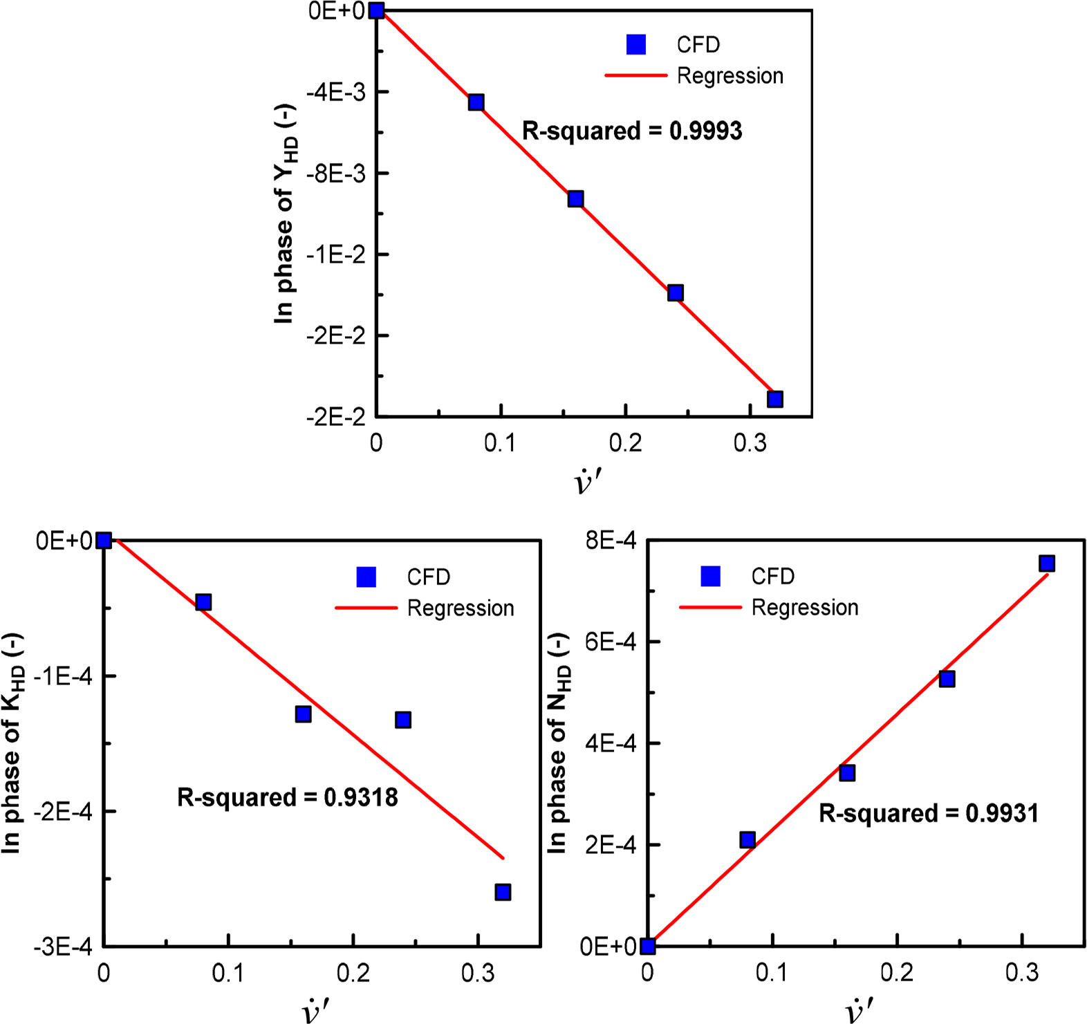
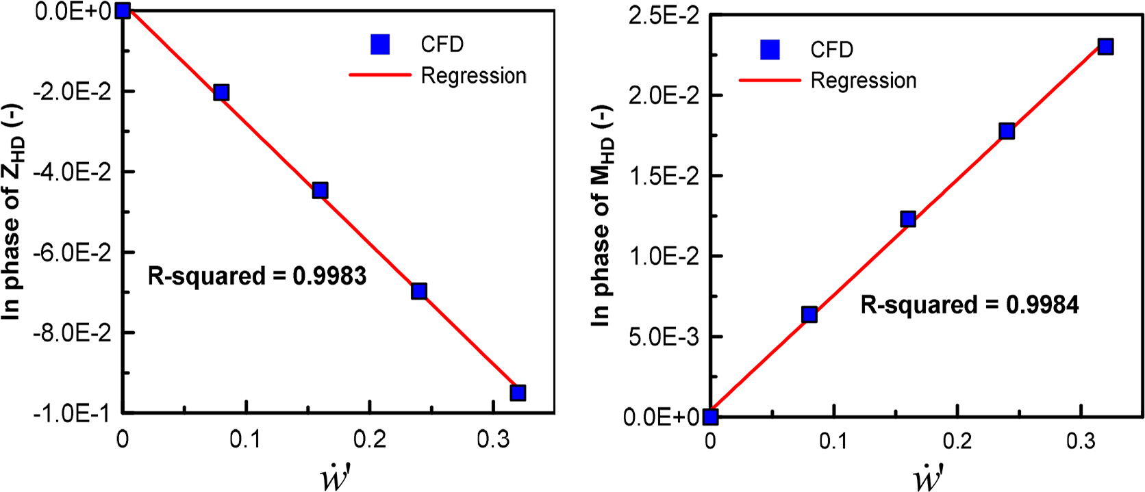
Figs. 16 and
17 present the results obtained from pure sway tests for estimating the added mass force with respect to sway acceleration
v̇ and pure heave tests for estimating the added mass force with respect to heave acceleration
ẇ, respectively. The added mass moment of inertia coefficients
Kv̇ and
Nv̇ for
v̇ are typically negligible, as well as the added mass moment of inertia coefficient
Mẇ for
ẇ; therefore, the sizes of
Yv̇ and
Zẇ need to be examined. The results obtained from comparing the sizes of
Yv̇ and
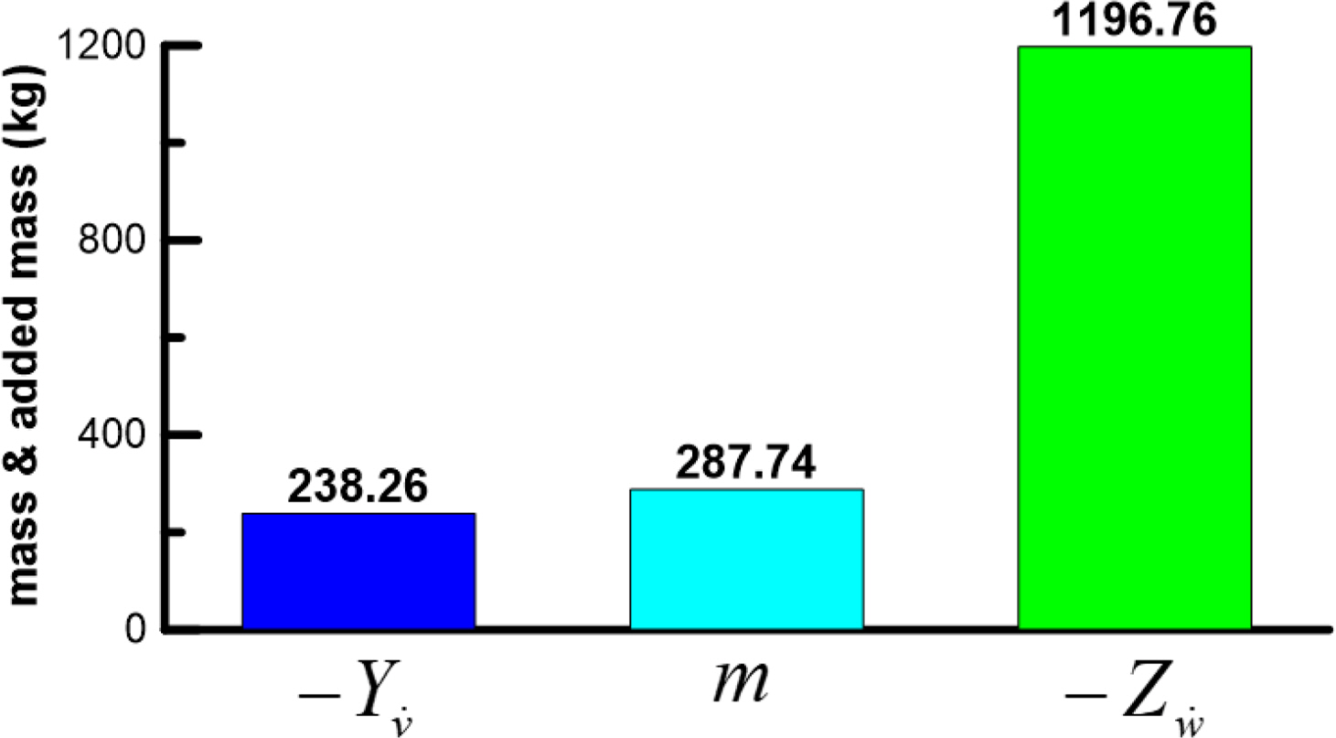
Zẇ with the mass of the submerged body are illustrated in
Fig. 18.
Yv̇ of a general ship has proportion of its mass. Furthermore,
Yv̇ and
Zẇ are identical in a submerged body with symmetrical horizontal and vertical planes. However, the subject submerged body in this study is applied with a relatively greater added mass force owing to its plate shape. Considering that the top surface area is at least twice as large as the side area and the top surface shape is a plate shape, rather than a streamlined shape, it is feasible for the size of
Zẇ to be greater than that of
Yv̇ and its own mass.
Figs. 19,
–
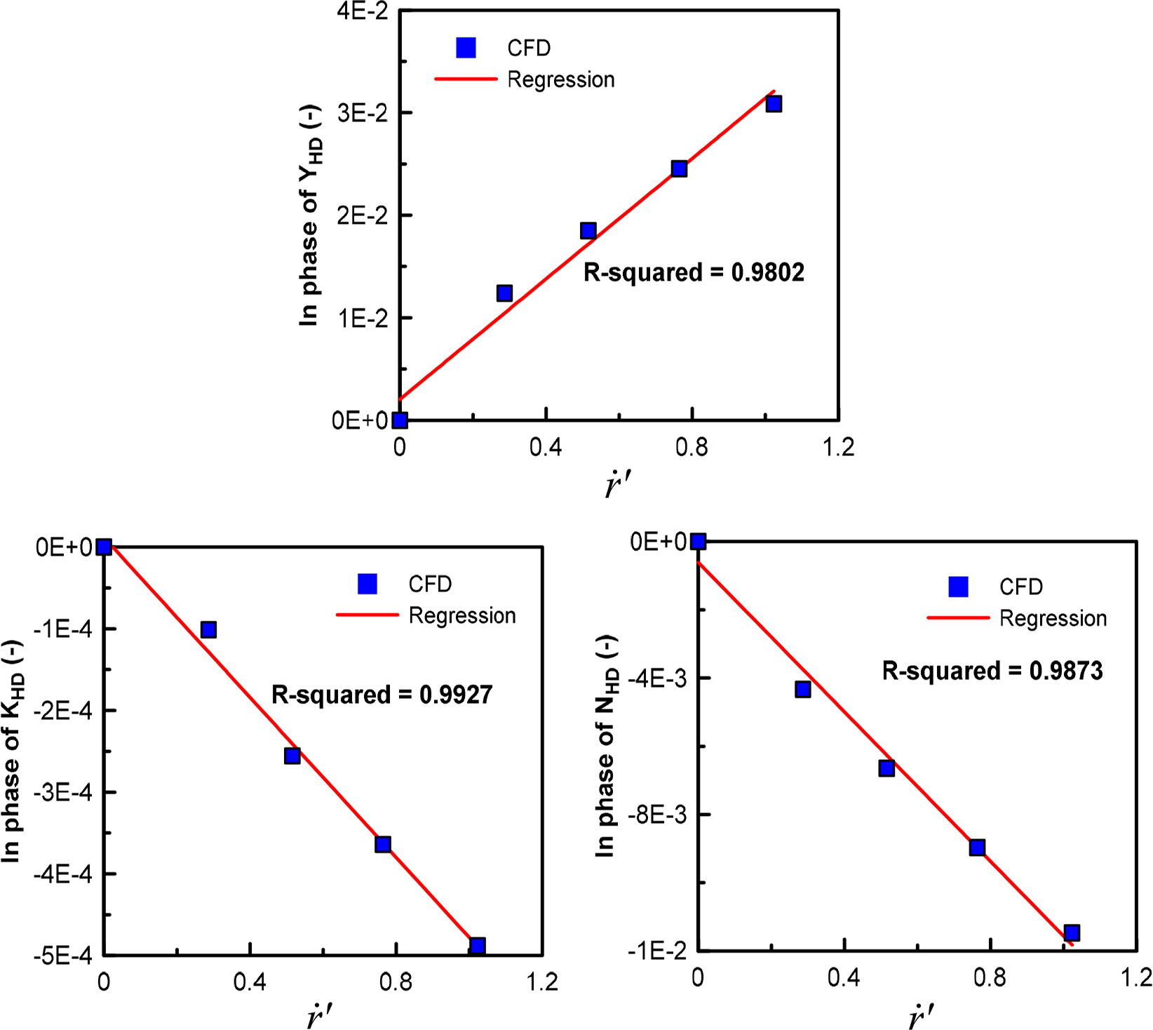
21 illustrate the results obtained from a dynamic test for angular acceleration.
Figs. 19 and
20 present the results obtained from estimating added mass coefficients for yaw angular acceleration
ṙ and pitch angular acceleration
q̇. Similar to the difference in the sizes of
Yv̇ and
Zẇ, the size of
Mq̇ is greater than that of
Nṙ because the top surface shape is more predominant than that of the side shape. In general, the added mass moment of inertia is sufficiently small to be negligible compared to the mass moment of inertia (
Ixx) in a submerged body with a streamlined shape when a roll angular acceleration
ṗ is generated. However, the subject submerged body has a relatively plate-like shape, and the slenderness ratio (
L/
B) is relatively small. Moreover, a large hydrodynamic moment is generated by a roll angular acceleration because the areas of bow and stern elevators are large. Consequently, the yaw induced mass moment of inertia
Kṗ is relatively larger than that of a general slender-type submerged body, as illustrated in
Fig. 21.
3.3 Dynamics Model
The six degrees-of-freedom equations of motion based on Newton’s second law of motion can be expressed as in
Eq. (1).
External forces on the right side of
Eq. (1) can be divided into hydrodynamic force, gravitational force, buoyant force, control force, and thrust. Hydrodynamic forces were modeled as expressed in
Eqs. (2) and
(3) by distinguishing linear models for designing the controller and stability analysis and nonlinear models for predicting maneuverability based on the coefficients identified via the static and dynamic tests.
Unlike other external forces contributing to the surface force, gravitational force and buoyancy are body forces that contribute to the volume, which do not require a modeling process as hydrodynamic forces, and can be perfectly expressed physically. Therefore, the expressions for gravitational force and buoyancy are omitted in this study because they can be referenced in the study by
Fossen (2011). A control force is a fluid force applied on the control panel and the hull when the control panel rotates.
Eqs. (4) and
(5) represent the control force of linear and nonlinear models, respectively. The parameters expressed in
Eqs. (2)–
(5) are presented in
Tables 6 and
7 by distinguishing between a linear and nonlinear model.
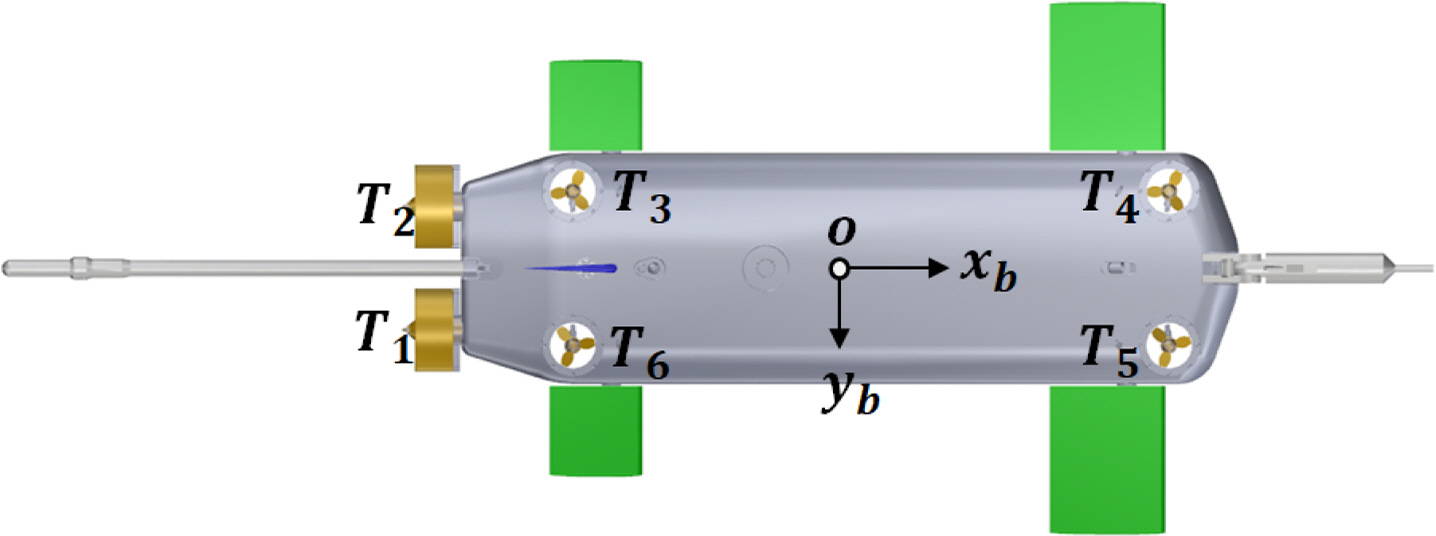
Because the system has six thrusters attached, the subjectsubmerged body can create thrust in all directions, except for the sway direction. Thrust force with six degrees of freedom generated by each thruster can be defined as expressed in
Eq. (6), based on
Fig. 22.
xTi,
yTi, and
zTi in
Eq. (6) represent the distance from the origin of the
i-th thruster to the
x-,
y-,
z-axes, respectively. The thrust specified in the specifications of each thrust manufacturer was adopted as the thrust defined by
T1–6.