 |
 |
- Search
| J. Ocean Eng. Technol. > Volume 35(4); 2021 > Article |
|
Abstract
In order to minimize carbon emissions and greenhouse gas, the Energy Efficiency Design Index (EEDI) has become a major factor to be considered in recent years in a ship’s design and operation phases. Energy-Saving Devices (ESDs) improve the EEDI of a vessel and make them environmentally friendly. In this research, the performance of an equalizing duct-type ESD installed upstream of a Korea Research Institute of Ships & Ocean Engineering (KRISO) Container Ship (KCS) model’s propeller was investigated by computational fluid dynamics (CFD). Open-source CFD libraries, OpenFOAM, were used for computational analysis of the KCS with and without the ESD to verify the performance improvement. The flow field near the stern region and propulsive coefficients were considered for comparison. The results showed a considerable improvement when an ESD was used on the model. Using different sizes of the duct, the performance of the ESD was also compared. It was observed that with an increased duct size, the propulsive performance was improved.
The enforcement of the energy efficiency design index (EEDI) as an approach to decarbonization has led to a focus on improvement and further verification of the hydrodynamic performance of energy-saving devices (ESDs) used on ships to improve propulsion efficiency. With screw propellers still being a dominant propulsion device, the need for energy savings and emissions reduction has prompted research in ESDs that are related to propulsion efficiency. An efficiently and optimally designed hull and propeller can significantly recover lost energy during propulsion when used in conjunction with the ESDs. In recent years, ESDs have been crucial for both old vessels seeking retrofitting and new buildings. The improvement in propulsion performance from these devices plays a crucial role in complying with the EEDI and reduction of fuel consumption.
Various types of ESDs are being used in the shipping industry. Some ESDs have been used to modify flows upstream and downstream of the propeller. An ESD in front of the propeller improves the inflow to the propeller plane. One downstream of the propeller makes use of the rotational flow of the propeller slipstream. In other cases, a composite device uses both mechanisms.
Kim et al. (2013) investigated a design of a duct-type ESD attached to the stern of a very large crude oil carrier (VLCC) hull. The research used computational fluid dynamics (CFD) simulation and considered the duct flow field, the hydrodynamic effects on resistance, and propulsive performance. Numerical flow analysis identified a reduction of hull resistance by the straightening effect of the stern flow and pressure recovery on the stern region. The power reduction was calculated to be 5%.
Bart and van Terwisga (2017) studied the effects of a duct and nozzles on propulsion devices. Koushan et al. (2020) considered a pre-swirl ESD that had fixed lifting foils mounted in front of a screw propeller. Using the lifting surface vortex model, the results showed an increase in 4% at the design point in comparison to when the ESD was not used. There are many ESDs that provide flow to the propeller by use of a pre-swirl stator (PSS) (Krol and Tesch, 2018; Henrich and Yan, 2017). The use of a composite device that incorporates a duct and pre-swirl stators has been extensively researched. The duct provides uniform velocity distribution to the propeller plane in addition to providing more thrust by use of the foil section. Such a device is a Mewis duct that incorporates fins to improve energy-saving performance (Mewis and Guiard, 2011).
When a duct is placed in front of a propeller, it has similar effects that are almost equal to those of a nozzle around a propeller. Nozzles around a propeller are used to improve efficiency of the propeller due to their ability to accelerate the flow through the propeller plane. An increase of flow to the propeller plane increases the mass flux through the propeller, in turn contributing to a high amount of efficiency. A duct used in the ducted propeller is also believed to cut down the amount of axial kinetic energy losses and increase the flow rate through the propeller disk. Furthermore, it can be used to capture the viscous wake through the propeller wake, thereby increasing the propeller-hull interaction contribution to the efficiency (Bart and van Terwisga, 2017).
CFD has become an essential tool for the design of an ESD due to its ability to analyze a detailed flow that cannot be captured in experimental methods. Open-source software has gained extensive use in the ship building industry in the study of resistance, self-propulsion, and ship motions in waves. Park et al. (2013) developed a solver using open-source libraries for shipbuilding. Shen et al. (2014) applied dynamic overset grids in OpenFOAM for the self-propulsion and maneuvering of the Korea Research Institute of Ships & Ocean Engineering (KRISO) container ship (KCS). Seo (2017) used OpenFOAM to study the effects of wave periods on added resistance and motion of a ship in head simulations. Go et al. (2017) studied the effects of a duct before a KP505 propeller on the propulsion performance without a hull form. From the results, it was found that the duct is applicable to high-speed vessels such as containers.
The present work discusses the use of an equalizing duct-type ESD located upstream of the KCS model’s propeller. The thrust improvement and flow through the duct have been analyzed to study the effects of the equalizing duct-type ESD. The duct was realized with a sectional NACA 4420 profile with an angle of attack of 20 degrees. Stators for the duct were not considered in this study. The performance of the KCS model with the equalizing duct-type ESD was compared with that of a KCS model without a duct. Three sizes of ducts were used for comparison to study how the duct’s size relative to the propeller diameter affects the generated thrust by the propeller.
Fig. 1 shows the baseline of the equalizing-type ESD. The hydrofoil cross section is a NACA4420. The hydrofoil has an angle of attack (AOA) of 20 degrees and constant duct length and chord length. The diameters (DESD) used were 0.6DP, 0.7DP, and 0.8DP, where DP is the propeller diameter. 0.8DP was used as the maximum outlet diameter since a diameter larger than that would extend beyond the model’s keel.
To ship studied follows the continuity and Navier-Stoke’s equations:
where U⃗ is the velocity vector, p is the pressure, ν is the kinematic viscosity, and νt is the turbulent kinematic viscosity. The k-w SST turbulence model was used for the turbulence closure (Menter, 1993). We captured the free surface using OpenFOAM’s multiphase solver with the volume of fluid (VOF) method and interFoam.
The Reynolds-averaged Navier Stokes (RANS) equations were discretized using the finite volume method (FVM). A second-order-accurate transient bounded-time-derivative Crank Nicolson scheme was used. The gradient schemes were discretized using the total variation diminishing (TVD) schemes with the van Leer limiter (van Leer, 1979). The second-order limited approach has been used to solve for the Laplacian term and the convection terms were solved using second-order schemes. The diffusion terms were solved using the central differencing schemes. The PIMPLE algorithm was used to couple the velocities and the pressure fields. The algorithm combines the “pressure implicit with splitting of operator” (PISO) method and semi-implicit method for pressure-linked equations (SIMPLE) (Gaggero et al., 2015).
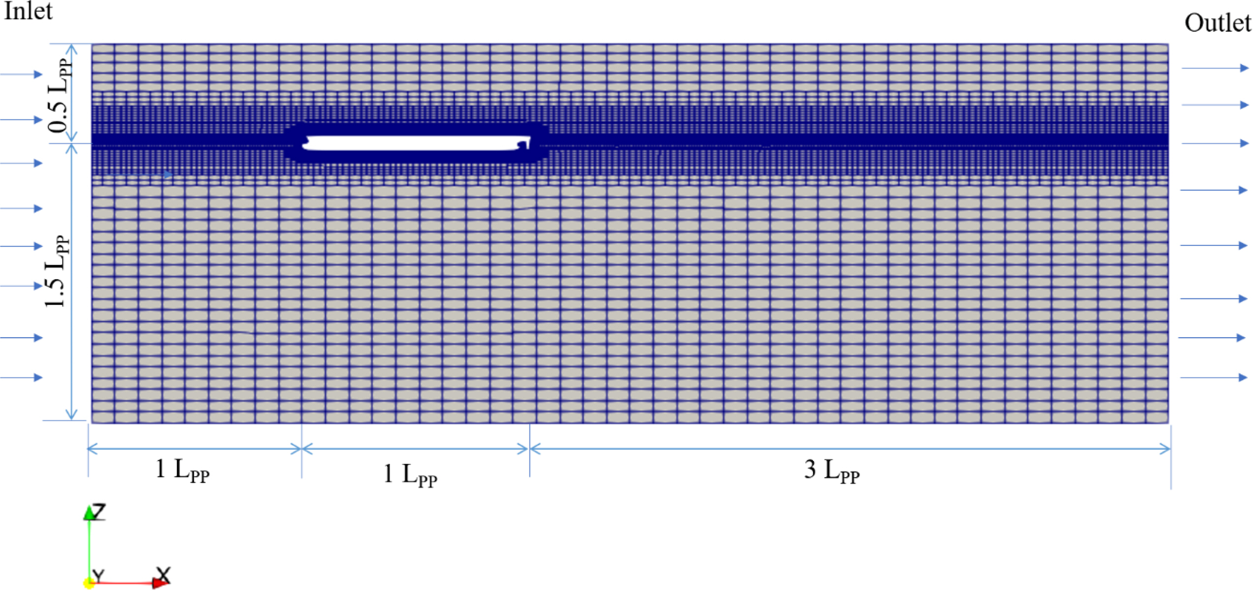
For the bare hull resistance of the KCS model, a computation was carried out at the design speed with a Froude number (Fn) of 0.26. Fig. 2 shows the grid and domain used for the resistance and propulsion. The domain extent was set to 1.0LPP in the forward direction, 3LPP in the stern direction, 1.0LPP in the width direction, and 0.5LPP and 1.5LPP above and below the free surface, respectively. LPP is the length between perpendiculars of the KCS model.
The Dirichlet conditions were applied for the velocity, turbulence, and volume fraction at the inlet boundary and the pressure at the outlet boundary. The Neumann conditions were applied for the pressure at the inlet boundary and the velocity, turbulence, and volume fraction at the outlet boundary. During forward ship motion in calm water, a wave is generated from the bow area, while in the stern region, flow separation occurs. Therefore, during mesh preparation, a high mesh resolution was given around the bow and stern region to capture the flow effects. In addition, the fluid interface region was also given high mesh resolution to accurately predict the ship resistance in calm water.
Table 1 shows the total resistance coefficient (
C T = R T / ( 1 2 ρ U 2 S )
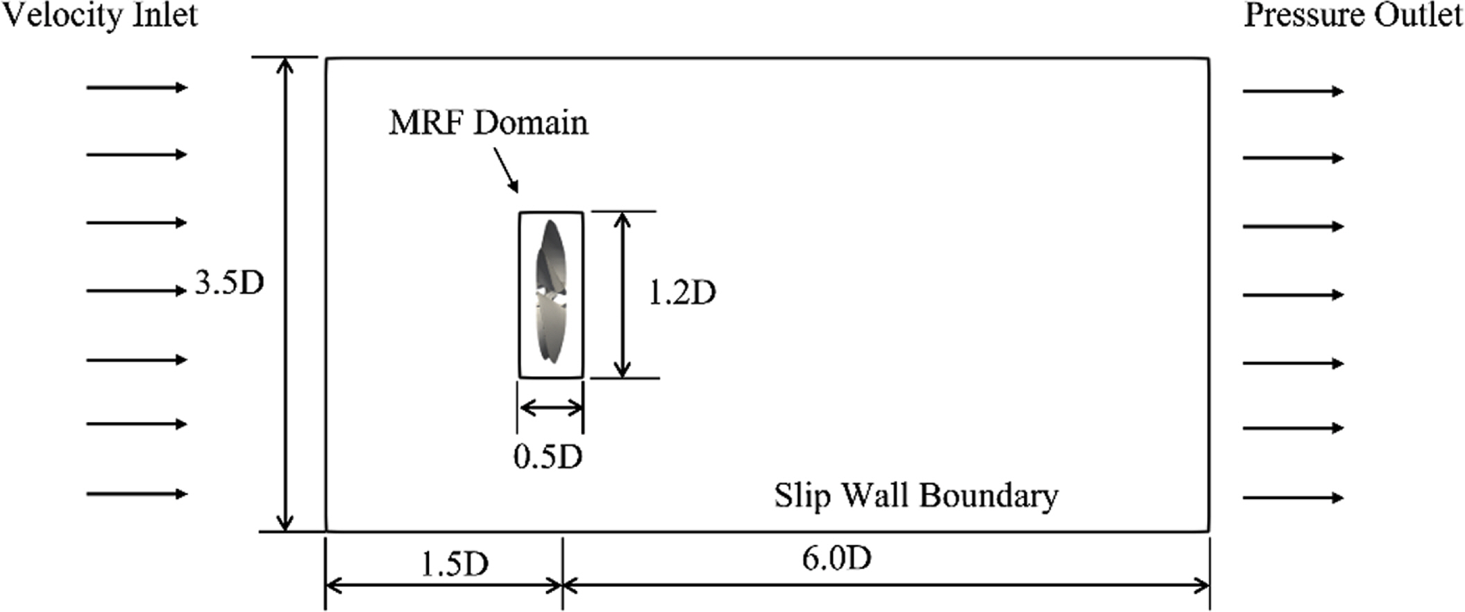
A steady-state solver with a moving reference frame (MRF) approach was used for computations of the complete propeller geometry. In the MRF approach, the simulation of the propeller is divided into two cell zones. The zone with the propeller is set as the rotating cell zone as shown in Fig. 3. The flow is inversely rotated instead of the actual propeller, so there is no actual relative propeller rotation. The MRF approach is fast, steady, and takes a short time to attain convergence. When using the MRF approach to solve the governing equations, the effects of centrifugal and Coriolis forces resulting from the angular velocity are considered as body terms in the momentum equations (Seb, 2017).
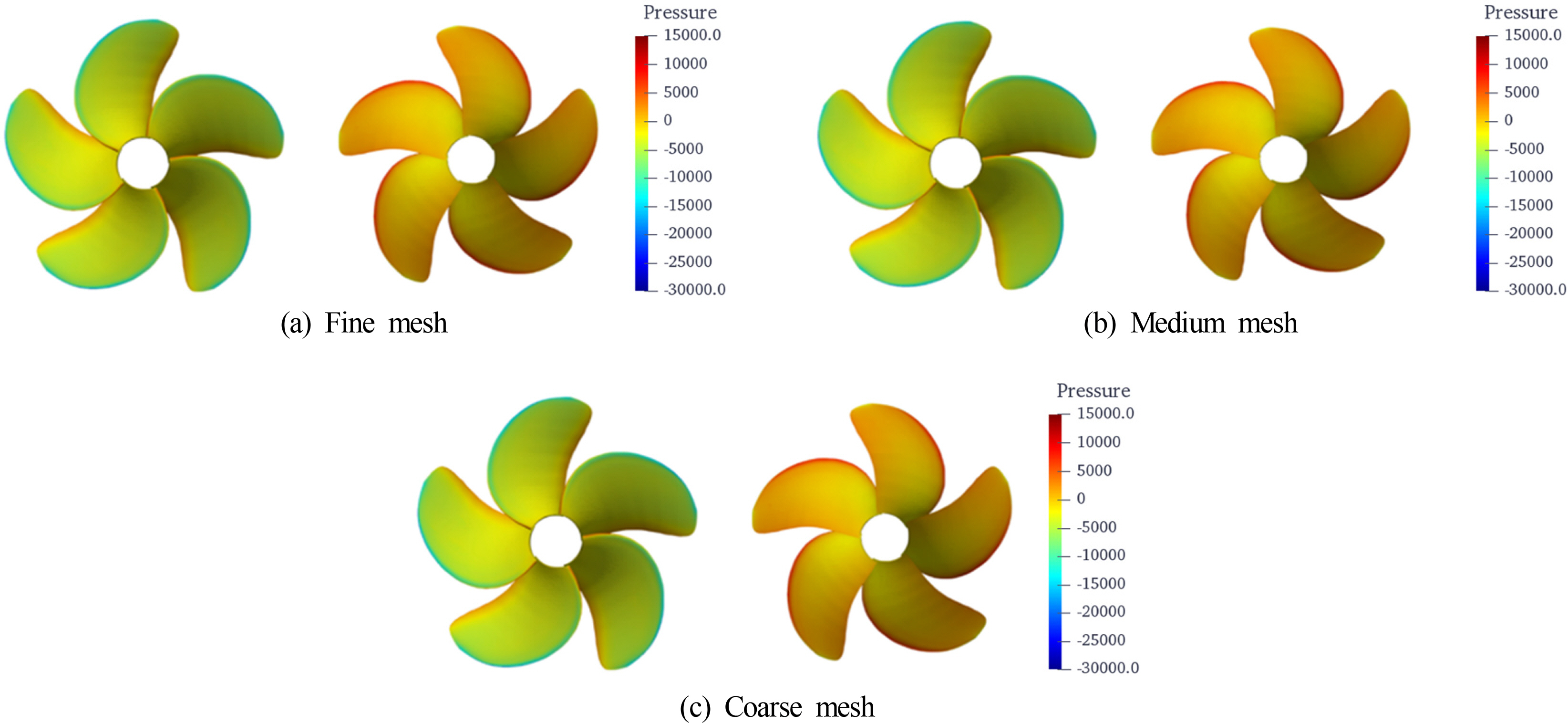
The number of cells in the open-water simulation was limited when considering self-propulsion. Fig. 4 shows the three grids. The meshes around the leading and trailing edges and tip were resolved. Fig. 5 shows the pressure contours at the pressure and suction sides of the propeller blades for three grids at an advance ratio (J) of 0.6. In the coarse mesh, low pressure at the tip was observed. Fig. 6 shows the POW results. The present data were compared with experimental data. The computational results agree with the experimental data, meaning the approach works well for open-water cases, and the propeller experiences a uniform inflow field. The error found between the present computation and experiment is generally low apart from the data at high advance coefficients.
For the computations of self-propulsion, an unsteady VOF solver was used with dynamic mesh motions and a sliding mesh to enable propeller rotation using the arbitrary mesh interface (AMI) method. The revolution speeds (n) were 9.5 rps and 10 rps. From the simulation values obtained for each revolution, balance is obtained, and linear interpolation is done to obtain the ship propulsion. To obtain the skin friction coefficient (SFC), a series of double body resistance computations was done at slow speed for a range of Fn ∊ [0.1, 0.2] using Prohaska’s method (Birk, 2019). The SFC was obtained as 32.2 N.
Table 2 shows the results for two revolutions at 9.5 rps, 10 rps, and the interpolation point. From the interpolation data in Table 2, revolution n = 9.998 was found to be the revolution at which the equilibrium point was obtained. The related thrust (T) of 67.032 and torque (Q) of 2.724 N·m are the parameters associated with the equilibrium point.
The result obtained from the KCS model without ESD can be compared with the experimental data and simulations (Larsson et al., 2015), and the results are shown in Table 3. At 9.5 rps, the computation overestimated the resistance by 4.2%. In the experimental data, the self-propulsion point was obtained at 9.5 rps, while in the present case, the self-propulsion point was obtained at 9.998. This variation can be attributed to a few factors, such as the number of grids due to the limitation of the number of cells used after considering the available computation resources. Also, the overestimation of the resistance could have contributed to this variance.
At the self-propulsion point, the value of KT was approximately equal to the experimental value of KT. Conversely, the value of KQ was underpredicted by around 3.125%. ηD is the ultimate goal for the self-propulsion computation in the present case and was underestimated by 3.784%, as shown in Table 3. Even though the thrust deduction shows some agreement with the experimental data, the effective wake coefficient shows a little discrepancy of about 3.535%.
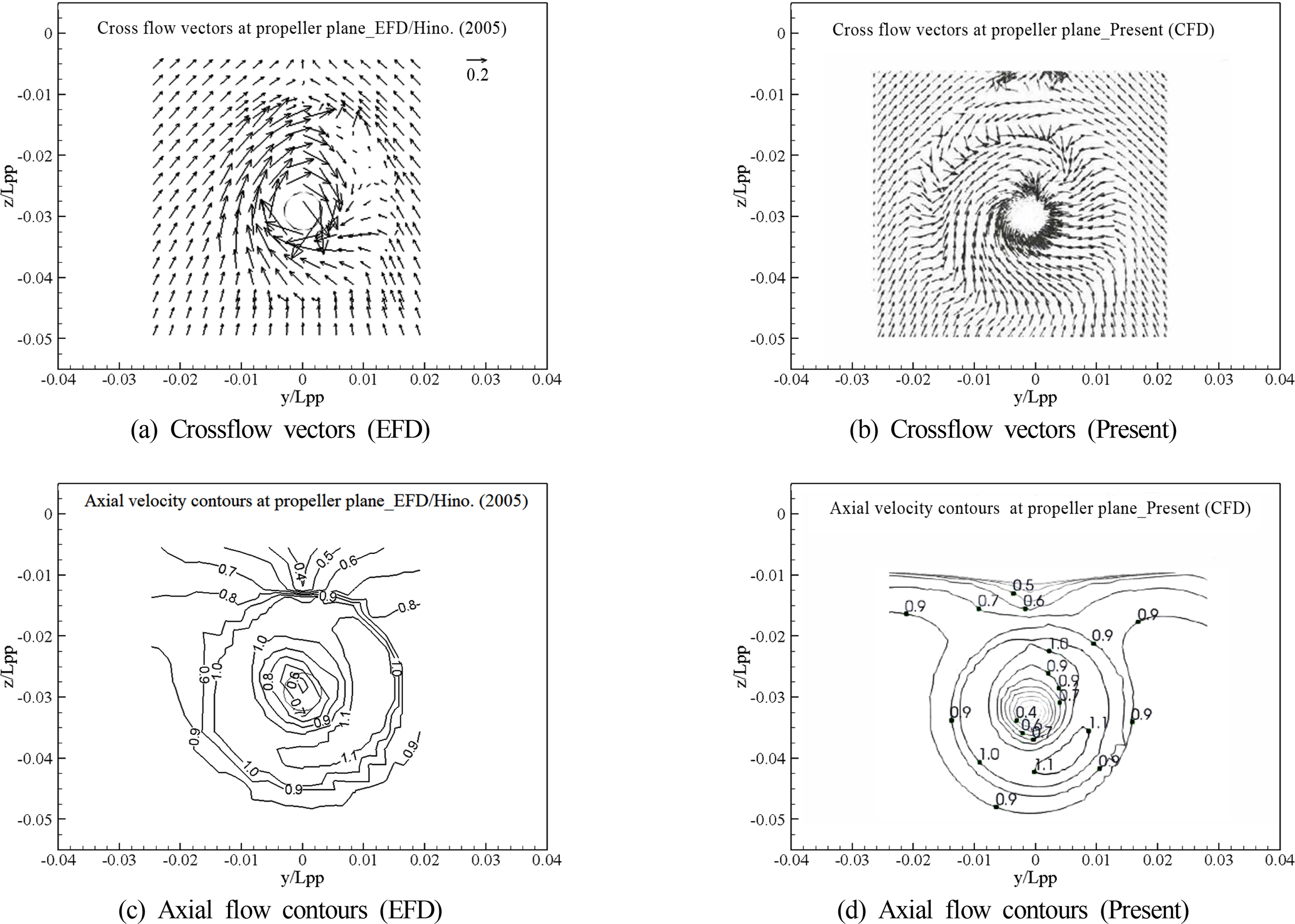
The cross-vector flows and axial flow contours were plotted for the KCS model during self-propulsion, as shown in Fig. 7. Wake contours were compared at x/LPP = 0.9911. For the overall wake shape, the results without ESD agree well with EFD data (Hino, 2005). The swirl in the present case seems to be overestimated.
This section presents data for a model with the equalizing duct-type ESD installed upstream of the propeller. The results were compared with the KCS model results without the ESD to analyze its effectiveness. Table 4 shows the results of self-propulsion with the equalizing duct-type ESD at DESD = 0.55DP. Revolution n = 9.89 was found to be the approximate revolution at which self-propulsion point was obtained. The thrust T = 66.855 N and torque Q = 2.600 N·m are the parameters associated with the self-propulsion point.
Table 5 compares the propulsive coefficients for the cases with and without the ESD. Considering the two scenarios for these cases, the thrust coefficient shows an increase when the ESD is used on the KCS model. The improvement of thrust delivered at the self-propulsion point represents a 2.35% increase when the two cases are compared. From the interpolation results, the KCS model with the ESD was observed to reach self-propulsion earlier at 9.89 rps as compared to the model without ESD at n = 9.998 rps.
Comparing the thrust for the two cases while on the same number of revolutions, the thrust for the KCS model with the ESD is greater than for the case without the ESD, as shown in Tables 2 and 4. This can be related to the flow that is directed to the propeller by the duct. The change in resistance values for both cases is insignificant. Comparing the quasi-propulsive efficiency of the ship model with and without the ESD, the performance shows improvement of about 3.929%, which is attributed by the improved upstream flow to the propeller.
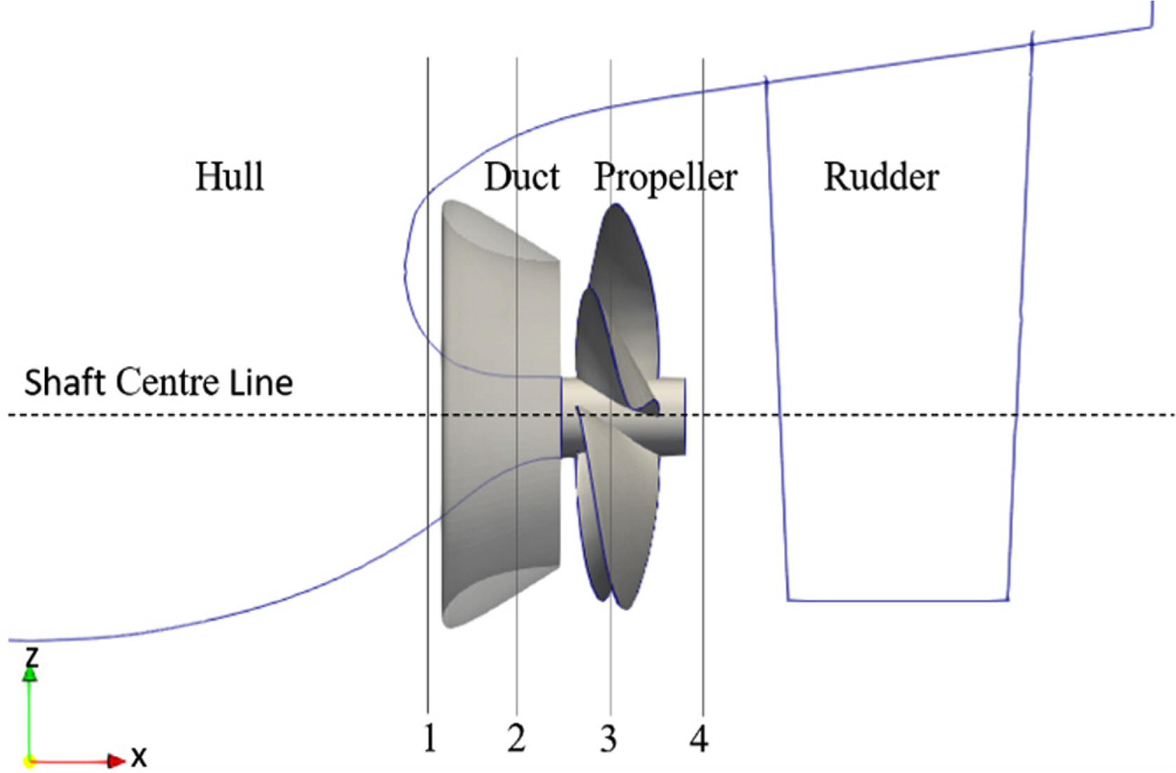
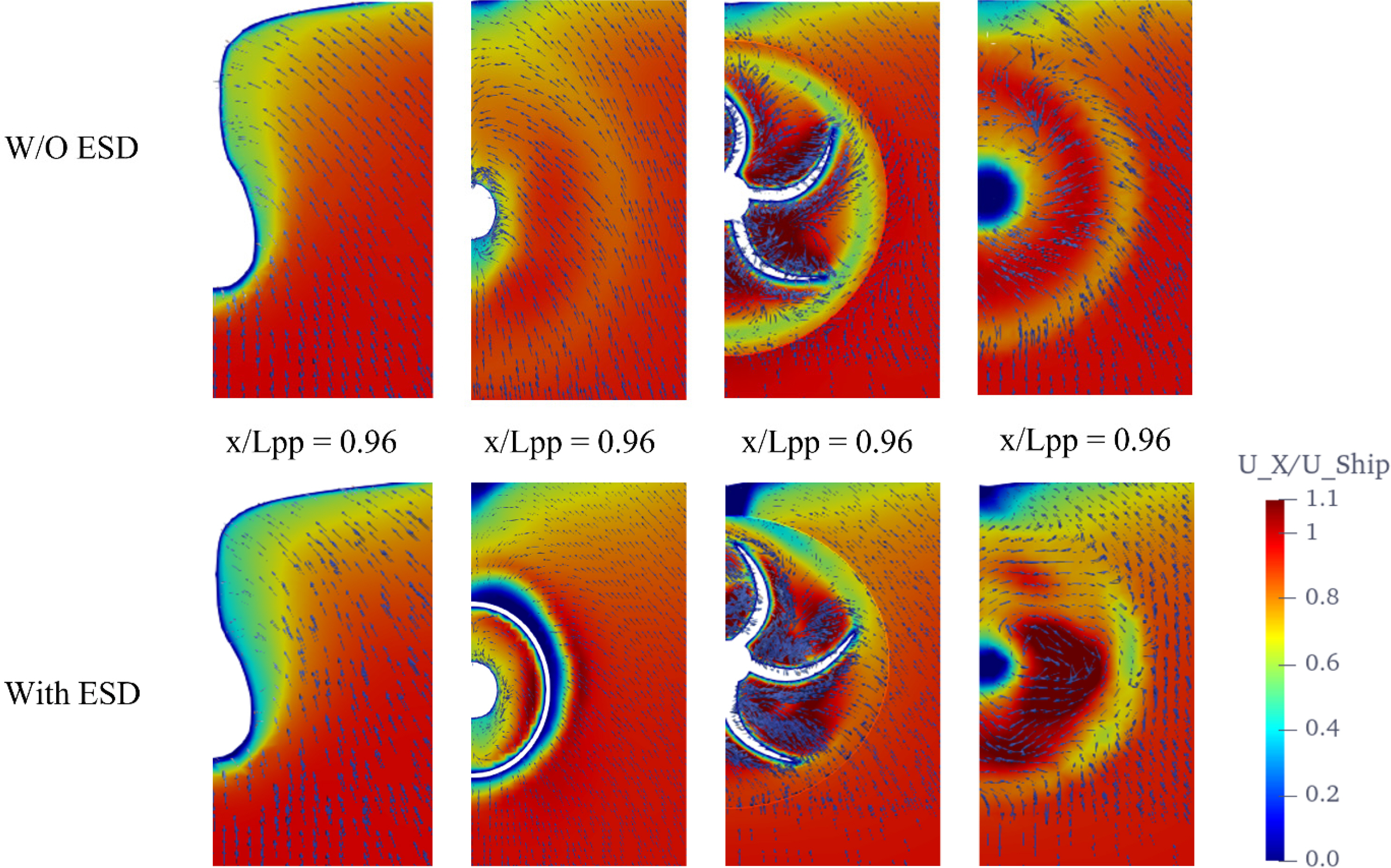
Different locations were considered to compare the effects of flow with and without the ESD at various points in the stern region around the propeller, as shown in Fig. 8. Flow-through points 1, 2, 3, and 4 represent x/LPP = 0.96, 0.97, 0.98, and 0.99, respectively, and are presented in Fig. 9. The axial flow distribution for the case with the duct is distinct in that fast flow induced by the duct is concentrated. Downstream of the duct, the duct’ effects are evident. There are distinct variations along the circumferential direction on the duct as the axial velocity near the outer side of the duct becomes weaker due to the duct’s angle of attack. On the stern side, the wake of the ship can be seen to influence the propeller, and the propeller also influences the ship flow.
Three outlet diameter sizes for the duct were considered and compared at 9.5 and 10 rps. The ducts had equal length and angle of attack with only a change in the diameter of the duct. The diameter of the baseline duct was 0.7DP. A bigger one (0.8DP) and a smaller one (0.6DP) were considered. 0.8DP was the maximum duct size that could have been used since a larger size would have extended below the keel. In comparison to the duct with an outlet diameter of 0.55DP, the ducts with larger diameters of 0.6DP, 0.7DP, and 0.8DP showed improvement in the propulsive performance at the self-propulsion point, as shown in Table 6. When the duct’s outlet diameter was 0.8DP, the results showed the highest thrust output compared to the other ducts sizes. With the increased diameter size, the thrust of the propeller was observed to improve.
In this type of hull design, the stern of the ship is well designed, so the difference of the resistance forces was insignificant for all cases with and without a duct. Therefore, the propeller performance became the focal point. In the performance comparison to the model without the ESD, all the cases with the ESD showed improved propulsive performance. This is shown in both Tables 5 and 6. Both the propeller thrust and torque increase with the size of the duct. With the increased size of the duct, Fig. 10 shows that the wake fraction (w) was increased, while the thrust ratio (t) was reduced, thereby increasing the hull efficiency performance.
Fig. 10(d) shows that the self-propulsion point was achieved earlier as the thrust generated by the propeller was higher than in the case without the ESD. The self-propulsion point was obtained with less revolution as the duct size increased, which was due to the increased thrust generated by the propeller. As the size of the duct increased, the overall efficiency ηD also increased.
The relative rotative efficiency is highest between 0.6DP and 0.65DP. At 0.8 DP, which is the highest size of the duct in this case, the relative rotative efficiency is almost equivalent to the case without a duct. In Fig. 10(f), the propulsive performance steeply increases until 0.7DP, and between 0.7DP and 0.8DP, the propulsive efficiency change is small, which may be a result of reduced relative rotative efficiency and open-water propeller efficiency. Despite the largest duct giving the highest propulsion efficiency, its relative rotative efficiency is almost equivalent to the case without a duct Fig. 10(e). It is insufficient to say that it is the most effective duct because this case requires a different angle of attack for comparison and other aspects of the design of the duct. The improvement in the performance of the propulsive system using the duct maybe attributed to enhancement of the mass flow rate passing through the propeller disk and the reduction of the drag force on the blades of the propeller.
Fig. 11 shows the pressure contours of the propeller blades for different outlet diameters of the ESD. The pressure of the suction side decreases with the increased diameter of the duct outlet. The pressure distribution on the propeller blade varies with the size of the duct, especially on the suction side. On the pressure side, higher pressure is observed on the tip of the propeller when a larger duct is used. This may lead to undesirable pressure loading on the propeller. The pressure loading on the tips shifted with the duct size, with a large diameter resulting in higher loading at the propeller tip than a smaller diameter.
This study presented a computational analysis for a KCS model with an ESD. The computations were done for cases with and without an ESD, and results were compared to study its effectiveness. For the propeller open-water test, the MRF approach was considered, and results were compared with experimental data. The data showed good agreement with the experimental data for the KCS model without the ESD. In the self-propulsion of KCS, non-dimensionless propulsive factors such as the thrust coefficient, wake fraction, and relative rotative efficiency with and without the ESD were compared.
The performance of the ESD showed some significant improvement in the propulsion. With increased size of the duct, the propeller thrust increased. The pressure loading shifted to the propeller blade tips as the duct size increased. However, there are many points to improve for further development in this case, such as coupling of the ship dynamic motion with the sliding mesh motion. Even though the comparison seems qualitatively promising, there is a need for further study to obtain more consistency, insights, and understanding in the future. In the future, more parameters such as the angle of attack and incorporation of fins should be considered.
Funding
This research was supported by the National Research Foundation of Korea (NRF-2018R1A1A1A05020799, NRF-2021R1I1A3044639).
Table 1.
Resistance results
| Grid sets | Background mesh | Number of grids | CT (×10−3) | Difference (%) |
|---|---|---|---|---|
| 1 | 45 × 11 × 28 | 4,023,280 | 3.840 | 3.457 |
| 2 | 32 × 9 × 20 | 2,157,269 | 3.878 | 4.511 |
| 3 | 25 × 6 × 15 | 1,362,365 | 3.957 | 6.638 |
Table 2.
Self-propulsion without ESD
| Revolutions (rps) | RT (N) | T (N) | Balance (T - RT(SP) + SFC) | Torque (N·m) | |
|---|---|---|---|---|---|
| Computation | 9.5 | 95.3 | 50.00 | −13.100 | 2.535 |
| 10 | 99.250 | 67.110 | 0.060 | 2.725 | |
| Interpolation | 9.998 | 99.232 | 67.032 | 0 | 2.724 |
Table 3.
Validation data for KCS model without ESD
| Item | EFD (NMRI) | KRISO | HSVA | SVA | Present | %D1) |
|---|---|---|---|---|---|---|
| KT | 0.170 | - | - | 0.172 | 0.588% | |
| 10KQ | 0.288 | - | - | - | 0.279 | −3.125% |
| 1-t | 0.835 | 0.846 | 0.865 | 0.910 | 0.835 | 0.0 % |
| J | 0.728 | 0.729 | 0.725 | 0.708 | 0.72 | 1.098% |
| η0 | 0.682 | 0.671 | 0.667 | 0.614 | 0.673 | −1.173% |
| ηR | 1.011 | 1.023 | 0.981 | 1.007 | 1.035 | 2.374% |
| 1-w | 0.792 | 0.779 | 0.789 | 0.765 | 0.819 | 3.409% |
| n | 9.500 | 9.380 | 9.560 | 9.500 | 9.998 | 5.242% |
| ηD | 0.740 | 0.746 | 0.717 | 0.618 | 0.710 | −4.054% |
Table 4.
Interpolation data for KCS model with ESD
| Revolution (rps) | RT (N) | T (N) | Balance | Torque (N·m) | |
|---|---|---|---|---|---|
| Computation | 9.5 | 95.767 | 51.502 | 12.067 | 2.105 |
| 10 | 99.850 | 70.401 | −2.750 | 2.712 | |
| Interpolation | 9.89 | 99.035 | 66.855 | 0 | 2.600 |
Table 5.
Comparison of KCS model data with and without ESD
| Item | Present w/o ESD | Present w/ESD |
|---|---|---|
| KT | 0.172 | 0.175 |
| 10KQ | 0.279 | 0.271 |
| 1-t | 0.835 | 0.837 |
| J | 0.720 | 0.715 |
| η0 | 0.673 | 0.67 |
| ηR | 1.035 | 1.058 |
| 1-w | 0.819 | 0.805 |
| n | 9.998 | 9.89 |
| ηD | 0.710 | 0.7379 |
Table 6.
Performance of KCS model with ESD and various DESD
References
Bart, S., & van Terwisga, T. (2017). Hydrodynamic Working Principle of Energy Saving Devices in Ship Propulsion Systems. International Shipbuilding Progress, 63(3–4), 255-290.
https://doi.org/10.3233/ISP-170134

Birk, L. (2019). Fundamentals of Ship Hydrodynamics (1ST ed) . New Jersey, USA. John Wiley & Sons, Ltd.
Gaggero, S., Villa, D., & Viviani, M. (2015). The KRISO Container Ship (KCS) Test Case: An Open-Source Overview. Proceedings of VI International Conference on Computational Methods in Marine Engineering (MARINE 2015). Rome, Italy. p 735-749.
Go, JS., Yoon, HS., & Jung, JH. (2017). Effects of a Duct Before a Propeller on Propulsion Performance. Ocean Engineering, 136, 54-66.
https://doi.org/10.1016/j.oceaneng.2017.03.012

Henrich, S., & Yan, X.-K. (2017). On the Working Principle of Pre-Swirl Stators and on Their Application Benefit and Design Targets. International Shipbuilding Progress, 63(3–4), 87-107.
https://doi.org/10.3233/ISP-170124

Hino, T. (2005). Proceedings of CFD Workshop Tokyo 2005. NMRI report 2005.
Kim, KS., Kim, YC., Kim, J., Lee, YY., Ahn, HS., Yim, GT., & Van, SH. (2013). Practical Application of CFD for Design of Energy Saving Devices Mounted on Ship stern. Proceedings of Twenty-third International Offshore and Polar Engineering Conference. Anchorage, Alaska.
Koushan, K., Krasilnikov, V., Nataletti, M., Sileo, L., & Spence, S. (2020). Experimental and Numerical Study of Pre-Swirl Stators PSS. Journal Marine Science Engineering, 8(1), 47.
https://doi.org/10.3390/jmse8010047

Krol, P., & Tesch, K. (2018). Pre-Swirl Energy Saving Device in Marine Application. Journal of Physics: Conference Series, 1101, 012015.
https://doi.org/10.1088/1742-6596/1101/1/012015

Larsson, L., Stern, F., Visonneau, M., Hirata, N., Hino, T., & Kim, J. (2015). Tokyo 2015: A Workshop on CFD in Ship Hydrodynamics. 2. Tokyo, Japan. National Maritime Research Institute (NMRI).
Menter, FR. (1993). Zonal Two Equations k-w Turbulence Models for Aerodynamics Flows. In 23rd Fluid Dynamics, Plasmadynamics, and Lasers Conference, American Institute of Aeronautics and Astronautics. Orlando, USA. AIAA-932906https://doi.org/10.2514/6.1993-2906

Mewis, F., & Guiard, T. (2011). Mewis Duct - New Developments, Solutions, and Conclusions. Proceedings of Second International Symposium on Marine Propulsors. Hamburg, Germany.
Park, S., Park, SW., Rhee, SH., Lee, SB., Choi, J.-E., & Kang, SH. (2013). Investigation on the Wall Function Implementation for the Prediction of Ship Resistance. International Journal of Naval Architecture and Ocean Engineering, 5, 33-46.
https://doi.org/10.2478/IJNAOE-2013-0116

Seb, B. (2017). Numerical Characterization of a Ship Propeller (Master Thesis). University of Zagreb; Zagreb, Croatia.
Seo, S., Park, S., & Koo, B. (2017). Effect of Wave Periods on Added Resistance and Motions of a Ship in Head Sea Simulations. Ocean Engineering, 137, 309-327.
http://dx.doi.org/10.1016/j.oceaneng.2017.04.009

Shen, Z., Carrica, PM., & Wan, D. (2014). Ship Motions of KCS in Head Waves with Rotating Propeller Using Overset Grid Method. Proceedings of International Conference on Ocean, Offshore and Arctic Engineering. San Francisco, California, USA. OMAE2014-23657, V002T08A043. https://doi.org/10.1115/OMAE2014-23657

van Leer, B. (1979). Towards the Ultimate Conservative Difference Scheme. V. A Second-order Sequel to Godunov’s Method. Journal of Computational Physics, 32(1), 101-136.
https://doi.org/10.1016/0021-9991(79)90145-1

- TOOLS
-
METRICS

-
- 2 Crossref
- Scopus
- 3,612 View
- 135 Download
- Related articles in JOET
-
Comparative Study on Numerical Analysis Methods on the 2D Ground Effect2007 June;21(3)
Numerical Analysis of Ship Local Resistance2012 December;26(6)
2D Computational Analysis of Overtopping Wave Energy Convertor2009 December;23(6)
Potential How Analysis for a Hull with the Transom Stern2001 February;15(1)


