1. Introduction
The importance of developing float-over installation technology and additional-structure designing technology for the safe installation of topside has increased in recent years owing to the increase in the size and weight of offshore plants. Float-over installation is one of marine construction methods used to load a completely constructed topside weighing tens of thousands of tons on an installation ship at a quay wall or pier, and then safely transport and install it on an offshore platform, to which the topside will be connected. Among the additional structures applied in the float-over installation method, a deck support frame (DSF), which can safely support a heavy topside, should be designed by applying classification rules considering actual operating conditions. For a DSF developed in a new format, weight-reduction design is crucial for ensuring the buoyancy and motion performance of offshore installation ships to which the DSF is applied, as well as for ensuring the safety of the structural design. This requires a design optimization that can satisfy the structural design safety of DSFs and secure a minimal weight simultaneously.
Studies that investigate the optimum design for offshore structures or related equipment have been conducted in a limited scope hitherto.
Song et al. (2011) conducted a reliability-based design optimization using a constraint-feasible moving least-squares method, which is a conservative approximation model, to minimize the design risk of floating production storage and offloading (FPSO) riser support.
Jung et al. (2009) investigated the impact load that can occur on a topside and an offshore structure’s platform during float-over installation.
Park et al. (2019) used design of experiments (DOE) to devise an optimum design method that can solve the resonance problem of radar mast occurring from the conventional operating area of the main engine of a large ship.
Park et al. (2011) conducted an optimum design using an evolution algorithm to minimize the design weight of support while satisfying the strength constraints provided in pipeline design regulations for FPSO flare systems.
Ji et al. (2015) used a genetic algorithm to develop an optimal arrangement design that can satisfy the stress and dynamic characteristics of resilient mounts installed for vessels.
In this study, structural analysis was performed using finite element method (FEM) to review the initial design of structural safety of passive type DSF, and an approximate optimization was performed using various surrogate models to obtain the most efficient optimum design results for the structural design of passive-type DSFs. Because newly developed offshore plant equipment such as passive-type DSF lack design information or validation data, surrogate-model-based approximate optimization results may not satisfy the constraint feasibility based on the characteristics of design problems. Therefore, it must be reviewed using various surrogate models. The approximate optimization method is often applied to multidisciplinary optimization and stochastic optimization, which require involved numerical calculations. If an appropriate surrogate model is selected based on a deterministic approximate optimization, then the efficiency of performing deterministic optimization such as reliability-based optimization can be increased. To evaluate the structural safety for the initial design of passive-type DSFs, design load conditions reflecting the classification rules were selected, and a three-dimensional (3D) structural analysis model was created using FEM to evaluate the strength performance for each design load condition. The optimum design problem was formulated to determine the thickness dimension variables of primary structural members that can minimize the total structure weight while satisfying all constraints of strength performance for each design load condition. For an approximate optimization, three surrogate models, i.e., the response surface method (RSM), Chebyshev orthogonal polynomials (COP), and Kriging model were applied to investigate the optimization design results, and the optimization results were compared based on the surrogate model characteristics. The results of approximate optimization methods by surrogate model characteristics were compared with the results of actual non-approximate optimization. Moreover, considering the optimum design characteristics and numerical calculation cost, the study was conducted to identify the most appropriate approximate optimization method for the structural design of passive-type DSFs. Among the surrogate models applied in this study, the approximate optimization method based on the RSM yielded the most efficient optimum design results for the structural design. Herein, Section 2 presents an FEM-based strength performance evaluation for each design load condition with respect to the initial structural design of passive-type DSFs. Section 3 provides a brief review of the surrogate model theory and summarizes the results of approximate optimization based on approximate model characteristics. Finally, the conclusions are presented.
2. Safety Evaluation of Initial Design Structure
A DSF is an offshore equipment mounted on a deck transportation vessel (DTV) for offshore plant installation to transport and install a constructed topside. It can be classified into truss-type, independent-structure-type, and beam-structure-type DSFs. As shown in
Fig. 1, the passive-type DSF considered in this study was developed to transport and install a 20,000-ton class topside; it was designed to accommodate a deck support unit (DSU) to finely adjust the height during topside installation at the center of the DSF. In the float-over method, the topside is loaded onto the passive-type DSF connected to the center of gravity of the DTV. Hence, the topside was connected to the offshore platform, which was installed in advance at the offshore field, as shown in
Fig. 1(a). As illustrated in
Fig. 1(b), the passive-type DSF was equipped with a DSU at the center, and it was designed to be 14 m wide and 6 m high. Furthermore, a 40-m-wide grillage was mounted on the DTV to prevent excessive strain on the DTV deck caused by the heavy topside, whereas the passive-type of DSF was installed on the upper side of the grillage.
To evaluate the structural safety in the initial design of the DSF, the design load conditions were first determined by applying the classification rules pertaining to the actual operating conditions. For the performance evaluation of the structural design, a 3D structural analysis model was created, and the design load conditions were applied to the structural analysis model to yield structural analysis results. Subsequently, the maximum stress was analyzed at each design load condition.
2.1 Design Load Cases
The design load cases for the structural performance evaluation of the passive-type DSF comprised four cases, as shown in
Table 1. These cases reflect the classification rules pertaining to the offshore installation operation (
DNV-GL, 2012;
DNV-GL; 2013,
GL, 2015a;
GL, 2015b). As shown in
Table 1, the design load cases comprised operation conditions for load-out and transportation, separately: the cases for load-out included weighing (LC1), initial (LC2), and skidding (LC3) cases, which reflected the operation conditions of loading a completely constructed topside on the passive-type DSF and shifting it to the DTV; the cases for transportation comprised the transport (LC4) case, which was for shifting the DTV, on which the topside and passive-type DSF were loaded, to the offshore platform. In the case of LC1, the topside weighing beam part was fastened, and the weighing load of the topside was applied to verify whether a heavy topside can be safely loaded onto the passive-type DSF. In LC2, the topside was connected to the passive-type DSF while considering the center of gravity of the topside after completing the weighing review prior to the load-out operation. In LC3, the topside-connected passive-type DSF was shifted to the DTV. In LC4, the topside-connected passive-type DSF was loaded, fastened, and transported to the grillage of the DTV.
The design load cases shown in
Table 1 were used as load conditions for FEM-based structural analysis, and
Fig. 2 shows the load and boundary conditions applied to the passive-type DSF in detail.
As shown in
Table 1 and
Fig. 2, for the load and boundary conditions of LC1, the weight of the topside was converted into a load and then applied in the gravity direction from the center of gravity, and the degree of freedom in the lateral direction on the fastened part of the topside weighing beam was constrained and considered. For the load and boundary conditions of LC2, the load of the topside weight was applied in the gravity direction from the center of gravity, and the degree of freedom in the lateral direction on the surface of lower part of the passive-type DSF was constrained and considered. For the load conditions of LC3, the weights of the topside and load-out equipment were applied in the gravity direction from the center of gravity, and the hydraulic operating force of a strand jack was applied in the load-out direction. Furthermore, as shown in the following equation specified in the classification rules, a static skidding force (
Fs) was applied in the opposite direction of the load-out direction (
DNV-GL, 2012;
GL, 2015a).
where
μud,s : static upper bound design friction coefficient (0.3)
W: topside weight
Weq : loadout equipment weight
Ps : inertial load or environmental load occurring during break-out
For the boundary conditions of LC3, the degree of freedom in the lateral direction on the surface of the lower part of the passive-type DSF was constrained and considered. For the load conditions of LC4, the load of the topside weight was applied in the gravity direction from the center of gravity, and the motion acceleration for each direction calculated through the motion analysis of DTV (
Kim et al., 2017) was considered and applied as an inertia load. In the boundary conditions of LC4, a contact condition was applied to the part where the passive-type DSF and the grillage coincided to consider the condition of the passive-type DSF loaded onto the DTV. In addition, eight steel tension wires that fastened the passive-type DSF on the DTV deck were idealized as 1-D rigid link elements, and the degree of freedom in the lateral direction was constrained. As for the allowable stress in the structural performance evaluation, the working stress design method (
DNV-GL, 2015) used in offshore structure designs was applied, where 85% of the material yield strength was considered.
2.2 Structure Analysis Results
FEM-based structure analysis was performed to evaluate the structural performance of the passive-type DSF designed for the installation of a 20,000-ton class topside on an offshore platform using the float-over method. The geometry used in the FEM modeling for the structure analysis is shown in
Fig. 3
As shown in
Fig. 3, the structure analysis model of the passive-type DSF was created using 717,452 elements and 654,452 nodes, including the DSF and the grillage based on the LC4 case provided in
Fig. 2. In addition, shell elements were applied for the primary structural members; meanwhile, the steel tension wires for fastening and the load-applied part were modeled using a rigid link. Among the structural members of the passive-type DSF, the API-5L-X52 material was used for the tube-shaped member, whereas the SM490YB material was used for the other members. The properties of these materials are summarized in
Table 2.
Based on the 85% yield strength of the classification rules, the estimated allowable stresses were 301.75 and 318.75 MPa for the SM490YB and API-5L-X52 materials, respectively. The structure analysis was performed using ABAQUS/Implicit (
Simulia, 2018), a general-purpose finite element analysis software. The results from the structure analysis are summarized in
Table 3 based on the von-Mises stress.
As shown in
Table 3, the maximum stress of the passive-type DSF satisfies the allowable stress of the classification rules for all design load conditions. Furthermore, the structural member of the SM490YB material indicated a higher stress level than the structural member of the API-5L-X52 material. In the case of LC3, the maximum stress level of the passive-type DSF was 297.3 MPa, which was similar to the limit of the allowable stress, indicating that this design load case requires precaution during design.
Fig. 4 shows the stress distribution of LC3 as a representative case.
In the conditions for LC3, as shown in
Fig. 4, the maximum stress of the passive-type DSF occurred at the internal connecting member of the lower part among the structural members of SM490YB material. Meanwhile, the structural member of API-5L-X52 material shows that the maximum stress occurred at the tube member connected to the position where the maximum stress occurred in the structural member of SM490YB material. Therefore, the weight must be minimized while the design load conditions of LC3 satisfied for structure optimization to achieve the minimum weight design of passive-type DSFs.
3. Approximate Optimization Design of Passive-Type DSF
Surrogate model-based approximate optimization methods were used in this study to derive efficient and optimal weight-reducing design approaches for the structural design of passive-type DSFs. Three surrogate models were used for the approximate optimization: the RSM, Kriging, and COP. The formulation for the optimum design problem was configured to determine the optimal thickness of the primary structural members to minimize the structure weight, while satisfying all the constraints of strength performance below the allowable maximum yield strength for each design load condition. The approximate optimization results were analyzed based on the surrogate model characteristics. Subsequently, by comparing them with the results of actual non-approximate optimization, the most appropriate approximate optimization method for the minimal-weight structural design of passive-type DSFs was identified. For the non-approximate optimization, we used sequential approximate optimization (SAO), which is used for typical constraint optimization problems (
Haftka and Gürdal, 1991).
3.1 Surrogate Model Theory
Surrogate models used for approximate optimization were developed to predict the response characteristics of a constraint function and the response characteristics of an objective function with minimal errors within a specified design scope. Furthermore, they are applied during optimization analysis to improve the convergence and numerical calculation speed. Surrogate models are generally developed using a regressive method of polynomial form or an interpolative method that considers the design area based on a stochastic method. In this study, an approximate optimization was performed using three surrogate models, i.e., the regressive methods of RSM and COP, and the interpolative method of Kriging. In this subsection, the three surrogate models are briefly described.
The RSM is expressed as a regression model of quadratic polynomial form using the least-squares method.
If an actual response vector
g and a matrix
Z of
k basic variables are provided from the experimental points calculated using DOE, then the relationship between
g and
Z can be expressed as follow (
Song and Lee, 2010):
If a least-squares function is applied to calculate the RSM’s approximation coefficient of vector AR after minimizing the random error vector e, and the approximation coefficient of the surrogate model is applied, then the regression surrogate model can be obtained.
The Kriging surrogate model is expressed as the sum of a global model exhibiting the global characteristics of the actual design space function to be approximated, and the local model corresponding to the deviation between the actual function and the global model, as follows (
Cho et al., 2009):
where
AK = {
a1,
a2, …,
ap}
T is a coefficient vector, and
Z(
x) = {
z1 (
x),
z2 (
x), …,
zp (
x)}
T is a global model vector defined by a design variable
x ∈
End.
E (
x) is assumed to be an independent normal distribution, and the response vector obtained from
n experimental points is defined as follows:
E(
x) is defined as Gauss function, i.e., a correlation function. It can be expressed as a spatial correlation of design data, as follows:
where
θ,
x∈
End, and the correlation matrix is a positive definite matrix with a diagonal element of 1. The correlation coefficient
θ can be calculated stochastically as the most likely correlation coefficient using maximum likelihood estimation, which maximizes the likelihood function.
The COP surrogate model for a quadratic polynomial regression model is defined as follows using Chebyshev orthogonal polynomial
Pn (
x) (
Baek et al., 2011).
where
p0 (x) = 1, n = 0
p1 (x) = x − x̄, n = 1
p2(x)=(x-x¯)2-a2-112h2, n = 2
pn(x) = pn−1(x) p1(x)− (n − 1)2 [a2 − (n − 1)2]
h2pn − 1(x)/[4(4(n − 1)2−1)], n = 3,4,5, …
where
x̄ is the mean of the design variable,
a the number of levels, and
h the level interval coefficient; the degree
n must be smaller than the number of levels
a, and the maximum degree of each design variable becomes
a − 1.
b is an approximate coefficient, which is defined by the as follows:
3.2 Formulation of Approximate Optimization Design
Fig. 5 shows the design variables and their range for the structural design optimization of the passive-type DSF considered in this study.
In the design variables, the upper and lower limits were applied to nine primary structural members of different thicknesses within ± 20% of the initial design thickness, as shown in
Fig. 5, and they were set considering the range that facilitated actual fabrication and production. The formulation for an optimum design was defined as follows to minimize the weight under the constraints of strength performance:
Subject to
g1(x1, x2, x3, x4, x5, x6, x7, x8, x9) = LC1 stress ≤ 301.75 MPa
g2(x1, x2, x3, x4, x5, x6, x7, x8, x9) = LC2 stress ≤ 301.75 MPa
g3(x1, x2, x3, x4, x5, x6, x7, x8, x9) = LC3 stress ≤ 301.75 MPa
g4(x1, x2, x3, x4, x5, x6, x7, x8, x9) = LC4 stress ≤ 301.75 MPa
68.0 ≤ x1 ≤ 102.0 [mm]
56.0 ≤ x2 ≤ 84.0 [mm]
48.0 ≤ x3 ≤ 72.0 [mm]
44.0 ≤ x4 ≤ 66.0 [mm]
40.0 ≤ x5 ≤ 60.0 [mm]
32.0 ≤ x6 ≤ 48.0 [mm]
24.0 ≤ x7 ≤ 36.0 [mm]
20.0 ≤ x8 ≤ 30.0 [mm]
16.0 ≤ x9 ≤ 24.0 [mm]
The upper limit applied to the non-equivalence constraints of
Eq. (8) was the design performance reference value for ensuring the structural safety of the passive-type DSF; it was set to less than or equal to 301.75 MPa, i.e., the allowable material yield strength of SM490YB material. Because the maximum stress from the LC3 conditions calculated from the initial values of the design variables (shown in
Table 3) was similar to the upper limit of the design, a weight-minimizing design method that satisfies the LC3 conditions must be identified when designing a passive DSF.
3.3 Approximate Optimization Process
The following approximate optimization was performed to compare approximate optimization methods based on the surrogate model characteristics for the structural design of passive-type DSFs.
In the DOE for creating a surrogate model, an orthogonal array design (Park, 2012) was used to construct the experimental matrix, and a structure analysis using the FEM was performed to generate experimental data for surrogate modeling.
Experimental data based on a structure analysis using the FEM were used to create surrogate models of RSM, Kriging, and COP for the objective function and constraint functions of Eq. (8).
The optimal solution was obtained by applying the SAO method using each surrogate model.
A structure analysis using the FEM was performed for the converged optimal solution to validate the feasibility of the constraint function of each approximate optimal solution.
Actual non-approximate optimization based on a structure analysis using the FEM was performed, and the approximate optimum design characteristics and numerical calculation costs were compared.
In the orthogonal array design used in the DOE of clause (1), a three-level experimental matrix was applied, and the experimental matrix was constructed for 243 times considering the lower, initial, and upper limits of the design variables shown in
Fig. 5. The SAO used in the approximate optimization using the surrogate model of clause (3) is a method of determining whether to perform repetitive optimization calculation through a sequential determination of the convergence of the optimal solution. This method involves a move limit strategy, which prevents excessive approximation by determining the moving distance (
Haftka and Gürdal, 1991). The surrogate model of the RSM developed for the design of the passive-type DSF is expressed as follows:
The correlation coefficients of the Kriging surrogate model obtained for the design of the passive-type DSF are summarized in
Table 4.
Furthermore, the COP surrogate model developed for the design of the passive-type DSF is expressed as follows:
where
p1 (x) = x1 − 20; p2 (x) = (x1)2 − 10.67; p3 (x) = x2 − 25;
p4 (x) = (x3)2 − 16.67; p5 (x) = (x3 − 30);
p6 (x) = (x5)2 − 24; p7 (x) = (x3 − 40);
p8 (x) = (x7)2 − 42.67; p9 (x) = (x5 − 50);
p10 (x) = (x9)2 − 66.67; p11 (x) = (x6 − 55);
p12 (x) = (x1)2 − 80.67; p13 (x) = (x7 − 60);
p14 (x) = (x3)2 − 96; p15 (x) = (x8 − 70);
p16 (x) = (x5)2 − 130.67; p17 (x) = (x9 − 85);
p18 (x) = (x7)2 − 192.67;
3.4 Approximate Optimization Results
Approximate optimal solutions were obtained by applying the RSM, Kriging, and COP surrogate models, separately, in the design range defined during the formulation of an approximate optimum design for the passive-type DSF. To compare the efficiencies of the approximate optimization results based on the surrogate model characteristics, an FEM structure-analysis-based non-approximate optimization was performed, through which the optimal solution was derived and compared with the result of approximate optimization. The convergence result of the approximate optimization was recalculated using the FEM structure analysis to validate the actual value. In
Table 5, the optimization results are summarized for the optimal design variable, satisfying the constraint feasibility; weight reduction, which is the objective function; and number of function evaluations (NFE).
Fig. 6 illustrates the optimization convergence results of the objective function.
As shown in
Table 5 and
Fig. 6, the approximate optimization result using the Kriging model indicated the most significant weight reduction. However, although the result of LC3 constraints satisfied the upper limit of the constraints in the approximate optimization, the actual constraint evaluation result showed that the feasibility was not satisfied. This is attributable to the design problem and the surrogate model’s characteristics; hence, it indicates that an approximate optimal solution may exist outside the feasible area because of the nonlinear characteristics of the constraint function. Therefore, such a Kriging-based approximate optimum design does not satisfy the constraints and hence cannot be used in passive-type DSF designs. The FEM-structure-analysis-based non-approximate optimization shows activated results for the upper limit of LC3 conditions, which is the most critical aspect in the design of passive DSFs. Under the LC3 conditions, the approximate optimization results of the RSM and COP were distributed in approximately 0.7% and 3.9% of the feasible range, respectively, compared with the FEM-structure-analysis-based non-approximate optimization results. These characteristics afforded increased structural safety with respect to uncertainties in design and manufacturing. Except for the Kriging-based approximate optimization, the RMS indicated the most significant weight reduction effect among the approximate optimization methods. Considering the initial design weight, i.e., 1,341 ton, of the passive-type DSF, the RSM-based approximate optimization yielded a 5.8% weight reduction. The convergence was excellent in the case of using Kriging since the NFE was the lowest; however, because the constraints of LC3 were violated, it can be concluded that the RSM-based approximate optimization demonstrated a more appropriate convergence. Based on the convergence results of the objective function and the NFE, it is concluded that the RSM is the most efficient method for the approximate optimization design of passive-type DSFs.
4. Conclusion
In this study, an approximate optimization was performed using various surrogate models to identify the most appropriate optimal design method for the structural design of passive-type DSFs. The efficiency and feasibility analysis of the approximate optimization was performed based on the characteristics of the surrogate models because a feasibility validation through approximate optimization or reliability analysis is crucial to enable the use of surrogate models in actual design problems. The primary findings of this study are as follows.
To evaluate the structural safety in the initial design of DSFs used to install a 20,000-ton class topside on an offshore platform using the float-over method, we determined the design load conditions by applying classification rules pertaining to actual operating conditions. For the performance evaluation of the structural design, a 3D structure analysis model using the FEM was developed, and the structure analysis results were obtained by applying the design load and boundary conditions to the structure analysis model. Subsequently, the maximum stress was analyzed at each design load condition.
The maximum stress of the passive-type DSF satisfied the allowable stress of classification rules at every design load condition. Furthermore, the structural members of SM490YB material showed a higher overall stress level than those of API-5L-X52 material. The maximum stress level of the passive-type DSF was similar to the allowable stress limit in the case of LC3, indicating that the weight must be minimized while the design load conditions of LC3 satisfied in the structure optimization for a minimum-weight design.
Three surrogate models were applied for the approximate optimization: RSM, Kriging, and COP models. An optimal design problem was formulated to determine the design variable of thickness for the primary structural members to minimize the structure weight while satisfying all the constraints of strength performance, i.e., less than or equal to the allowable maximum yield stress at each design load condition. RSM, Kriging, and COP surrogate models were applied, separately, for the design scope defined during the approximate optimum design formulation to obtain the approximate optimal solutions. To compare the efficiencies of approximate optimization results based on the surrogate model characteristics, an FEM-structure-analysis-based non-approximate optimization was performed to derive optimal solutions, which were compared with the results of approximate optimal solutions.
In the approximate optimum design of passive-type DSFs, the result of approximate optimization using Kriging demonstrated the most significant weight reduction; however, the constraint evaluation indicated poor feasibility. The results of approximate optimization using Kriging showed that the result of LC3 constraints satisfied the upper limit of the constraints in the approximate optimization; however, because the feasibility was poor based on the actual constraint evaluation, we concluded that Kriging cannot be used when designing an actual passive-type DSF. Compared with the initial design weight of the passive-type DSF, the RSM-based approximate optimization indicated a 5.8% weight reduction. Furthermore, based on the convergence results of objective functions and the NFE, it is concluded that the RSM is the most effective method for the approximate optimization design of passive-type DSFs.
Based on the results of this study, we plan to conduct a study pertaining to stochastic optimization, such as robustness and reliability-based optimum designs, in the future.
Funding
This research was supported by a grant from the National R&D Project of “Development of Core Installation Technologies for Float-over and Dual Crane Methods” funded by Ministry of Oceans and Fisheries, and KIAT grant funded by the Korea government (MOTIE) (P0001968, The competency development program for industry specialist).
Fig. 1.
Topside mating procedure via float-over installation with passive type DSF
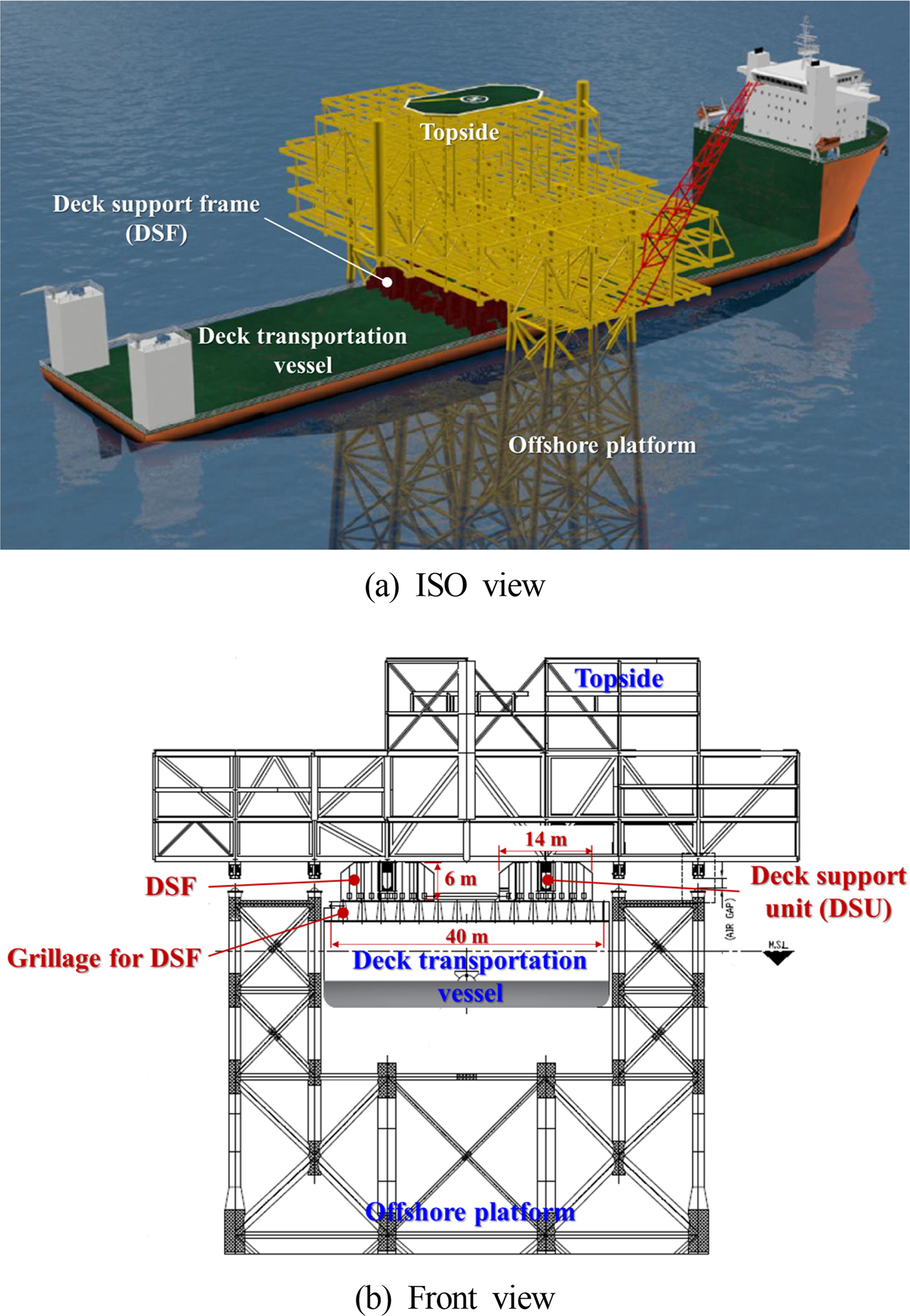
Fig. 2.
Load and boundary conditions for structure analysis of DSF

Fig. 3.
FEM model of passive type DSF

Fig. 4.
Stress contour results of LC3
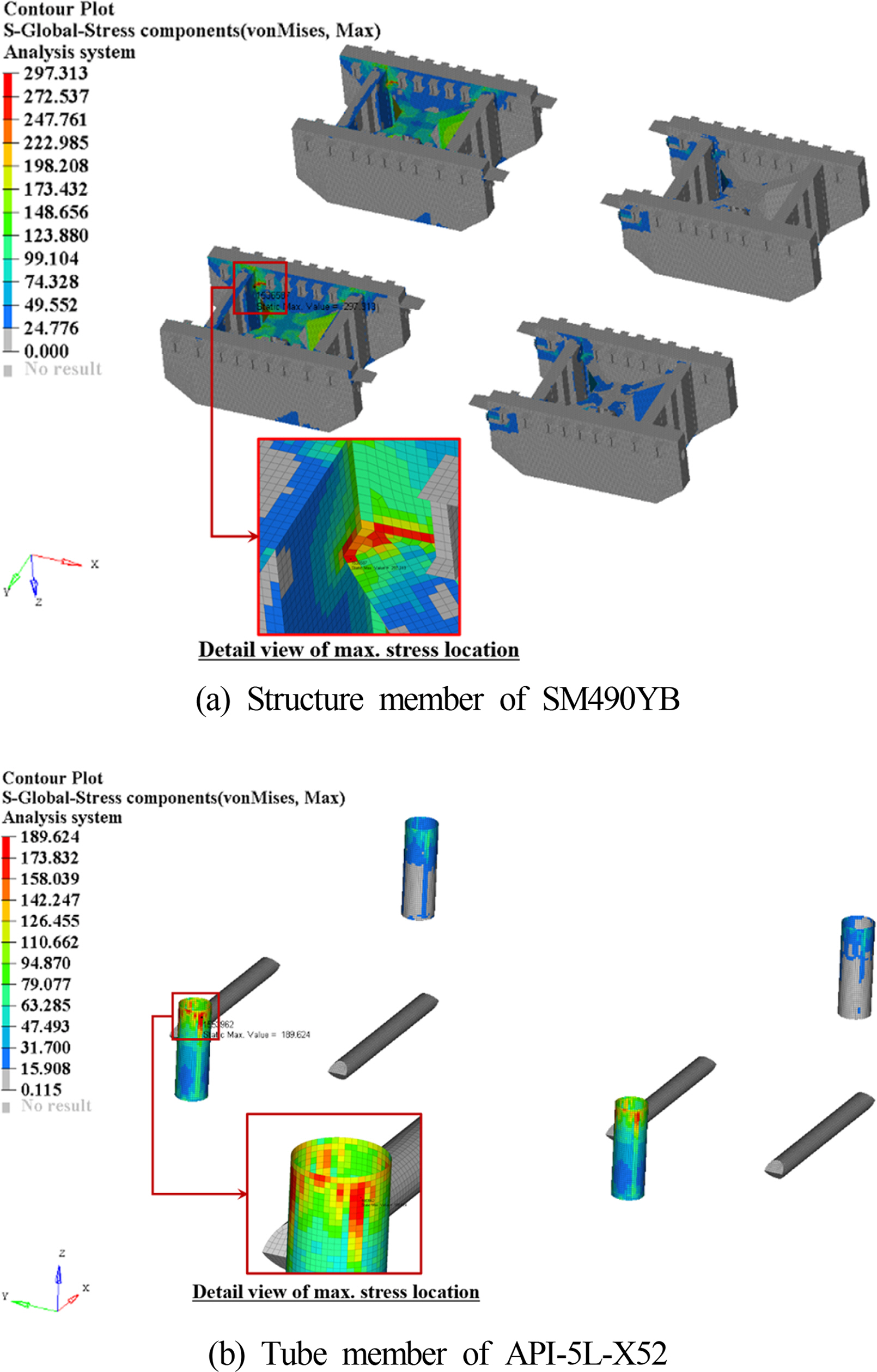
Fig. 5.
Design variables and their range for passive type DSF
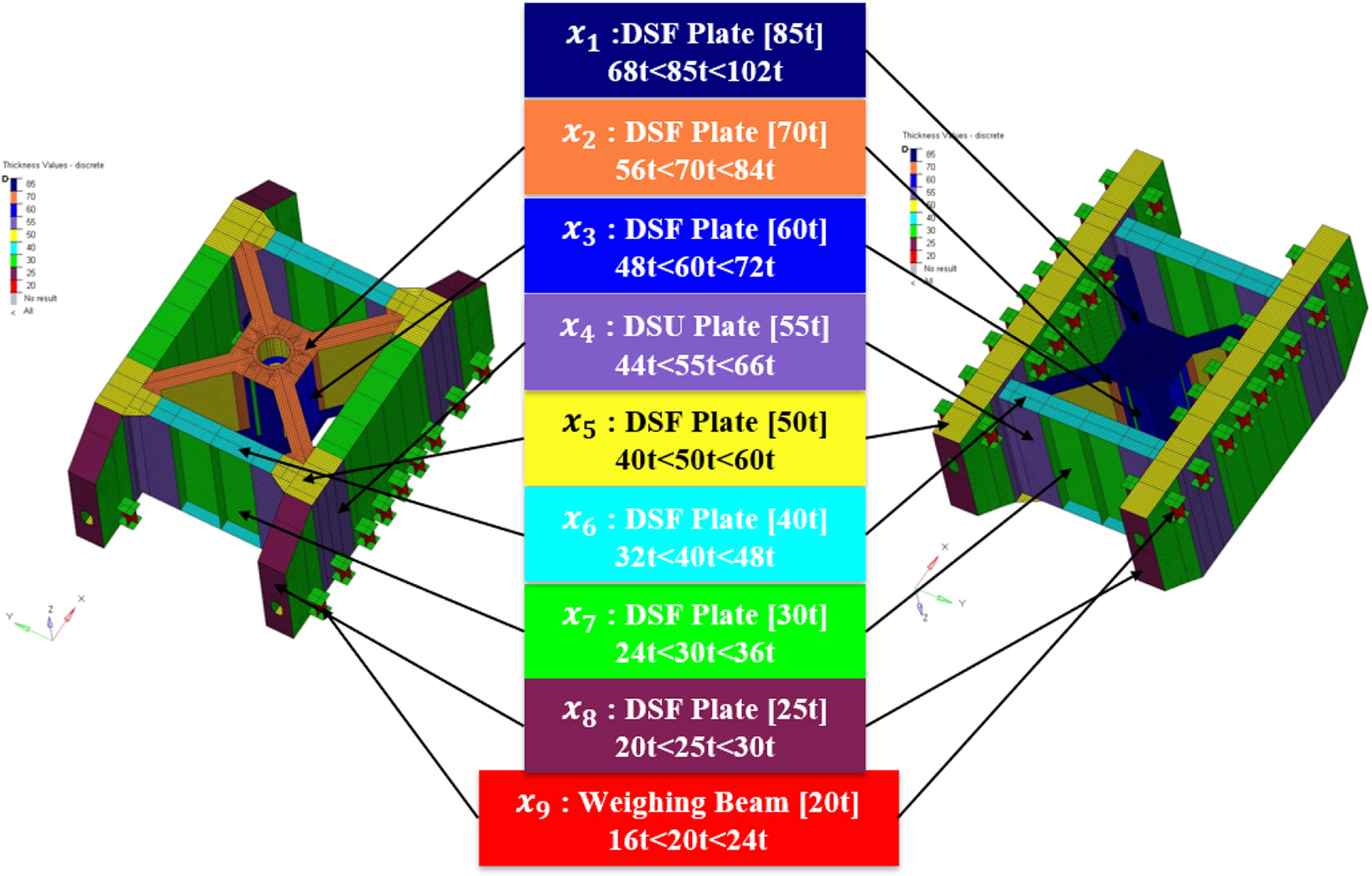
Fig. 6.
Iteration history of objective functions
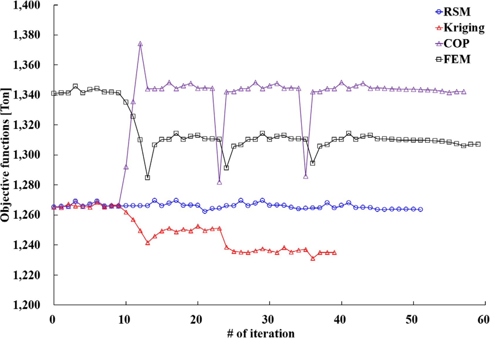
Table 1.
Design load case for structure analysis of passive type DSF
|
Operation condition |
Design load case |
Reference to rule & guidance |
|
Load-out |
LC1 - weighing
LC2 - initial
LC3 - skidding |
- Guidelines for load-outs
- Load transfer operations |
|
Transportation |
LC4 - transport |
- Guidelines for marine transportations
- Offshore installation operations |
Table 2.
|
Material property |
SM490YB |
API-5L-X52 |
|
Elastic modulus (N/mm2) |
206,000 |
208,000 |
|
Poisson’s ratio |
0.3 |
0.3 |
|
Density (N-s2/mm4) |
7.85E-9 |
7.85E-9 |
|
Yield strength (MPa) |
355 |
375 |
Table 3.
Structure analysis results of passive type DSF
|
Design load case |
Max. stress (MPa) |
Structure safety |
|
|
SM490YB |
API5LX52 |
|
LC1 |
244.023 |
0.952 |
OK |
|
LC2 |
194.926 |
120.139 |
OK |
|
LC3 |
297.313 |
189.624 |
OK |
|
LC4 |
153.521 |
103.403 |
OK |
Table 4.
Correlation coefficient of Kriging surrogate model
|
Response |
Correlation coefficient |
|
|
x1
|
x2
|
x3
|
x4
|
x5
|
x6
|
x7
|
x8
|
x9
|
|
W̃(x)K − mass
|
0.843 |
0.222 |
1.386 |
0.052 |
0.942 |
0.834 |
0.003 |
0.332 |
0.101 |
|
g̃(x)K − LC1
|
0.491 |
0.019 |
0.682 |
0.083 |
0.954 |
1.134 |
0.094 |
0.705 |
0.349 |
|
g̃(x)K − LC2
|
0.265 |
0.018 |
0.671 |
0.113 |
1.062 |
0.859 |
0.133 |
0.406 |
0.853 |
|
g̃(x)K − LC3
|
0.631 |
0.578 |
0.760 |
0.041 |
0.888 |
0.457 |
0.091 |
0.240 |
0.658 |
|
g̃(x)K − LC4
|
1.511 |
0.374 |
0.757 |
0.18 |
0.772 |
0.005 |
0.691 |
0.071 |
0.198 |
Table 5.
Comparative results of approximate optimization
|
Method |
Optimum (mm) |
Objective (t) |
Approximate constraint (MPa) |
Actual constraint (MPa) |
NFE |
|
RSM |
x1 = 20 |
1263.70 |
g1 = 213.24
g2 = 202.28
g3 = 301.75
g4= 163.73
|
g1 = 229.08
g2 = 199.88
g3 = 299.34
g4 = 167.54 |
260 |
|
x2 = 30 |
|
x3 = 24 |
|
x4 = 48 |
|
x5 = 40 |
|
x6 = 66 |
|
x7 = 48 |
|
x8 = 70 |
|
x9 = 105 |
|
|
Kriging |
x1 = 21 |
1235.18 |
g1 = 221.01
g2 = 200.79
g3 = 301.15
g4 = 171.26 |
g1 = 217.78
g2 = 202.23
g3 = 303.871)
g4 = 166.16 |
200 |
|
x2 = 27 |
|
x3 = 25 |
|
x4 = 47 |
|
x5 = 41 |
|
x6 = 63 |
|
x7 = 48 |
|
x8 = 70 |
|
x8 = 100 |
|
|
COP |
x1 = 19 |
1336.80 |
g1 = 237.67
g2 = 195.53
g3 = 301.75
g4 = 162.39 |
g1 = 238.43
g2 = 192.53
g3 = 289.96
g4 = 152.73 |
290 |
|
x2 = 33 |
|
x3 = 27 |
|
x4 = 48 |
|
x5 = 46 |
|
x6 = 65 |
|
x7 = 47 |
|
x8 = 70 |
|
x8 = 100 |
|
|
FEM (Non-approximate) |
x1 = 18 |
1,217 |
- |
g1 = 269.38
g2 = 200.56
g3 = 301.752)
g4 = 169.16 |
- |
|
x2 = 29 |
|
x3 = 19 |
|
x4 = 48 |
|
x5 = 43 |
|
x6 = 63 |
|
x7 = 46 |
|
x8 = 70 |
|
x8 = 97 |
References
Baek, SH., Kim, HS., & Han, DS. (2011). Structural Optimization of Variable Swash Plate for Automotive Compressor Using Orthogonal Polynomials.
Transactions of the Korean Society of Mechanical Engineers - A,
35(10), 1273-1279.
https://doi.org/10.3795/KSME-A.2011.35.10.1273

Cho, SK., Byun, H., & Lee, TH. (2009). Selection Method of Global Model and Correlation Coefficients for Kriging Metamodel.
Transactions of the Korean Society of Mechanical Engineers - A,
33(3), 813-818.
https://doi.org/10.3795/KSMEA.2009.33.8.813
DNV-GL. (2012). Load Transfer Operations. Det Norske Veritas.
DNV-GL. (2013). Offshore Installation Operations. Det Norske Veritas.
DNV-GL. (2015). Structural Design of Offshore Units WSD (Working Stress Design) Method. Det Norske Veritas.
GL. (2015a). Guidelines for Load-outs. GL Noble Denton.
GL. (2015b). Guidelines for Marine Transportations. GL Noble Denton.
Haftka, RT., & Gürdal, Z. (1991). Elements of Structural Optimization. Dordrecht, Netherlands. Kluwer Academic Publishers.
Ji, YJ., Kwak, JS., Lee, HY., & Kim, SC. (2015). Optimal Arrangement of Resilient Mount installed on Frame Support Structure at Shipboard Equipment under Shock Load.
Journal of the Society of Naval Architects of Korea,
52(4), 298-304.
https://doi.org/10.3744/SNAK.2015.52.4.298
Jung, JJ., Lee, WS., Shin, HS., & Kim, YH. (2009). Evaluating the Impact Load on the Offshore Platform During Float-over Topside Installation. Proceedings of 9th International Offshore and Polar Engineering Conference. Osaka, Japan. p 205-210.
Kim, HS., Kim, BW., Jung, D., & Sung, HG. (2017). Numerical Study for Topside Effect on Behavior of Deck Transportation Vessel and Seafastening Structure.
Proceedings of OCEANS 2017. Aberdeen, UK:
https://doi.org/10.1109/OCEANSE.2017.8084841
Park, JM., Park, CH., Kim, TS., & Choi, DH. (2011). Optimal Determination of Pipe Support Types in Flare System for Minimizing Support Cost.
Journal of the Society of Naval Architects of Korea,
48(4), 325-329.
https://doi.org/10.3744/SNAK.2011.48.4.325
Park, JH., Lee, D., Yang, JW., & Song, CY. (2019). Design Enhancement to Avoid Radar Mast Resonance in Large Ship Using Design of Experiments.
Journal of Ocean Engineering and Technology,
33(1), 50-60.
https://doi.org/10.26748/KSOE.2018.088
Park, SH. (2012). Design of Experiments. Seoul, Korea. Minyoung Publishing.
Simulia. (2018). Abaqus User Manual. Simulia.
Song, CY., Lee, J., & Choung, J. (2011). Reliability-based Design Optimization of an FPSO Riser Support Using Moving Least Squares Response Surface Meta-models.
Ocean Engineering,
38(1), 304-318.
https://doi.org/10.1016/j.oceaneng.2010.11.001
Song, CY., & Lee, J. (2010). Comparative Study of Approximate Optimization Techniques in CAE-based Structural Design.
Transactions of the Korean Society of Mechanical Engineers -A,
34(11), 1603-1611.
https://doi.org/10.3795/KSME-A.2010.34.11.1603


