Numerical Study on Taylor Bubble Rising in Pipes
Article information
Abstract
Slug flow is the most common multi-phase flow encountered in oil and gas industry. In this study, the hydrodynamic features of flow in pipes investigated numerically using computational fluid dynamic (CFD) simulations for the effect of slug flow on the vertical and bent pipeline. The compressible Reynold averaged Navier-Stokes (RANS) equation was used as the governing equation, with the volume of fluid (VOF) method to capture the outline of the bubble in a pipeline. The simulations were tested for the grid and time step convergence, and validated with the experimental and theoretical results for the main hydrodynamic characteristics of the Taylor bubble, i.e., bubble shape, terminal velocity of bubble, and the liquid film velocity. The slug flow was simulated with various air and water injection velocities in the pipeline. The simulations revealed the effect of slug flow as the pressure occurring in the wall of the pipeline. The peak pressure and pressure oscillations were observed, and those magnitudes and trends were compared with the change in air and water injection velocities. The mechanism of the peak pressures was studied in relation with the change in bubble length, and the maximum peak pressures were investigated for the different positions and velocities of the air and water in the pipeline. The pressure oscillations were investigated in comparison with the bubble length in the pipe and the oscillation was provided with the application of damping. The pressures were compared with the case of a bent pipe, and a 1.5 times higher pressures was observed due to the compression of the bubbles at the corner of the bent. These findings can be used as a basic data for further studies and designs on pipeline systems with multi-phase flow.
1. Introduction
Multiphase flow could be encountered in many industrial fields, such as chemical processing, nuclear cooling systems, and oil and gas industries. The oil and gas industry is the most common industry where multiphase flow can occur among them due to the complex processes and oil and gas production, such as drilling, oil and gas transportation from a well to a refinery plant, and separation devices.
The flow patterns/flow regimes can be classified into several types according to the flow rates, the geometry of the system, and the inclination of the pipe in the gas-liquid flow in pipes, such as bubbly flow, slug flow, plug flow, annular flow, and dispersed flow (Brennen, 2005). One of the most common and complex flow regimes is slug flow. Slug flow is identified by the large bullet-shaped bubble occupying more than 60% of the cross-sectional area of the pipe, which is well-known as a Taylor bubble (Davies and Taylor, 1950).
This flow can cause severe internal pipe corrosion, a structural vibration leading to fatigue failure or resonance, and poor reservoir management in oil and gas systems. For a better understanding of slug flow, many experimental studies have been conducted. Among them, the particle image velocimetry (PIV) method is mostly used to measure the flow behavior around the Taylor bubble (Polonsky et al., 1999; Van Hout et al., 2002; Nogueira et al., 2006). Van Hout et al. (2002) investigated the flow field induced by a Taylor bubble rising in a motionless water condition using the PIV method. They measured the average velocity of 100 bubbles and the instantaneous bubble in three different areas. They reported that a rising bubble would not affect the liquid if the liquid was more than 0.5 diameters away from the bubble nose or 12 diameters away from the bubble tail. Nogueira et al. (2006) adopted the PIV method and pulsed shadow technique (PST) to obtain better visualization of the bubble. The velocity field around the bubble and the bubble shape were measured under stagnant and flowing liquid conditions. The results showed that the bubble shape is strongly dependent on the liquid viscosity.
Although remarkable experimental studies have been conducted to understand slug flow behavior, computation is still necessary to understand the complex nature of slug flow because of the experimental limitations and difficulties. Early numerical studies on slug flow in a vertical pipe revealed computational fluid dynamics (CFD) to be the most effective method to overcome the experimental limitations and study the hydrodynamic characteristics of slug flow in a pipe. Kawaji et al. (1997) reported that the bubble length does not affect the bubble terminal velocity in a stagnant liquid through a vertical pipe using the volume of fluid (VOF) method. Clarke and Issa (1997) proposed a new numerical model that accounts for the small-dispersed bubble behind a Taylor bubble. The model revealed inaccurate results against their assumption. Therefore, they suggested that a future model should use two-fluid model to simulate slug flow with dispersed bubbles properly. Bugg et al. (1998) studied the hydrodynamics characteristics of slug flow in a vertical pipe using VOF. They showed that the results, including bubble shape, bubble rising velocity, liquid film thickness, had good agreement with the experimental data in the literature.
The VOF method is one of the powerful methods that is used widely in this topic (Ndimisa et al., 2005; Taha and Cui, 2006; Zheng and Che, 2007). Among them, Taha and Cui (2006) have published remarkable work. The author discovered that the character of the wake pattern behind the bubble region could be divided by an inverse viscous number, and the change in the liquid viscosity and surface tension results in a change in bubble shape. Later, Kang et al. (2010) discovered that the Archimedes number determines the size of the wake region. Yan and Che (2011) performed a numerical study on the mechanism of slug flow-induced CO2 corrosion with and without dispersed bubbles. More recently, Massoud et al. (2018) considered dimensionless parameters in the analysis to understand the Taylor bubble rising problem. The correlation, which consists only of the Reynolds and the Froude number, was introduced to calculate the bubble rise velocity.
Despite the significant numerical and experimental studies published on Taylor bubble flow in pipes, they focused mainly on the hydrodynamic features of slug flow; hence, the pressure data induced by slug flow is limited. To investigate the pressure induced by slug flow, a simulation was performed by changing the air injection velocity in the vertical pipe. The effect of the bubble length on the pressure oscillation in the vertical pipe was found, and the peak pressure at different air injection velocities was analyzed. The pressure damping in the pipe was studied using a method to calculate the roll-damping coefficient for the lateral motion of a ship. The bent pipe was studied under the same simulation conditions as the vertical pipe to examine the effects of geometry on the peak pressure in a pipe. In addition, the effects of a change in the air injection velocity on the peak pressure were compared with the effects of a change in the water velocity on the peak pressure.
2. Computational Setup
2.1. Model Geometry
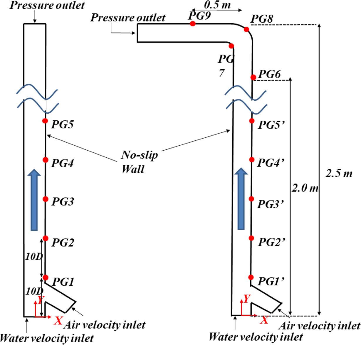
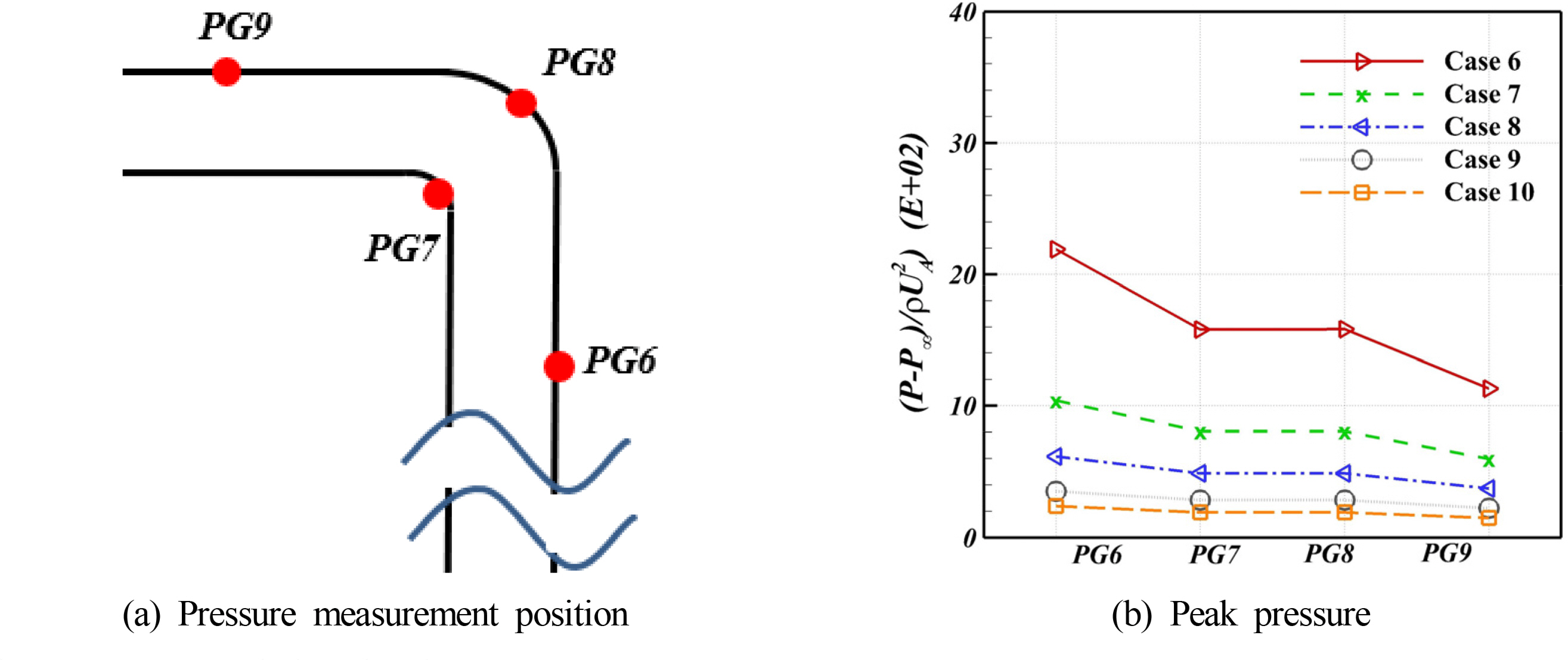
Fig. 1 shows a schematic image of the vertical with the details of two inlets. A 32 mm diameter vertical pipe, 2.5 m in length, with two inlets, one for the water inlet and the other for the air inlet, was used to simulate air-water slug flow in a vertical pipe. Once a certain amount of air was injected, a bubble was self-generated due to the buoyancy induced by the density difference between the water and air. The pressure fluctuations on the wall were monitored using five probes for the simulation time at five different locations (PG1, PG2, PG3, PG4, and PG5). In addition, the same diameter pipeline but bent at 2.5 m was also used to determine the effects of slug flow on a curved pipe wall. Fig. 1(b) presents the bent pipeline geometry. Air was injected through the air inlet at different velocities. Pressure monitors were placed at different positions (PG6, PG7, PG8, and PG9); the solution domain refers to the experiment by Nogueira et al. (2006).
2.2 Governing Equation
The CFD software Star-CCM+ (CD-Adapco, 2015) was used to simulate the single Taylor bubble rising in the vertical and bent pipe in the co-current condition. In Star-CCM+, the finite volume method (Hirsch, 1988) was considered to discretize the governing equations. As governing equations, continuity Eq. (1) and the Reynolds-averaged Navier-Stokes (RANS) equation (Eq. (2)) are used as follows:
To consider the energy convergence and compressibility of air, the energy convergence equation (Eq. (3)) and the ideal gas equation (Eq. (6)) were used in the study.
The Volume of Fluid (VOF) method developed by Hirt and Nichols (1981) was used to track the interface of air and water. The VOF method calculates the volume fraction of the gas and volume fraction of liquid in every computational cell, as shown in Eq. (7).
2.3 Convergence and Turbulent Model Test
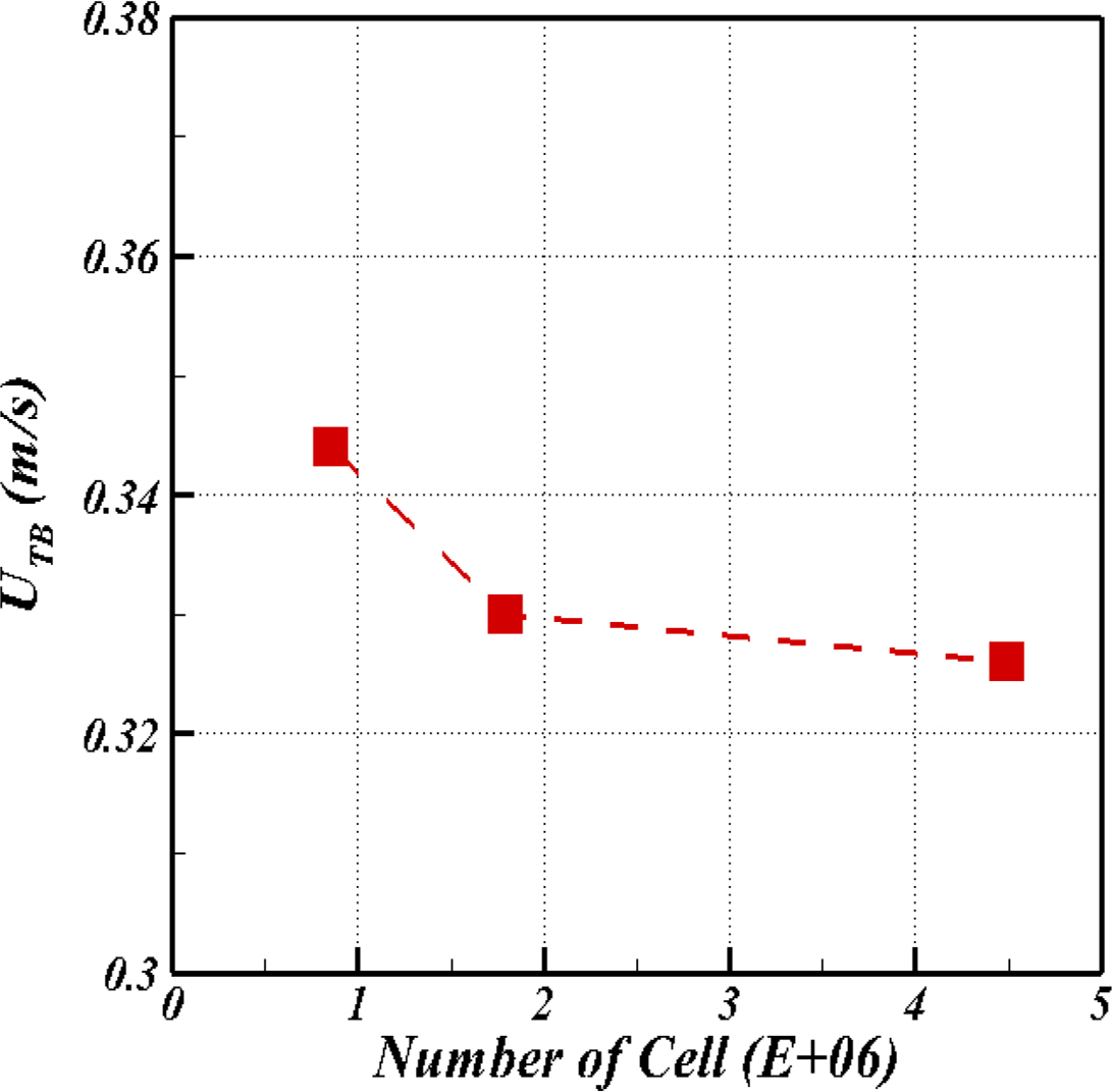
Before examining the effect of slug flow in a pipe using the CFD tool, the grid convergence test was performed about the terminal velocity, which is the constant speed due to the restraining force exerted by the fluid and is one of the main hydrodynamic features of slug flow. The CFD simulations at a liquid velocity of 0.074 m/s, which corresponds to the Reynolds number based on the bubble terminal velocity (ReUTB) of 325 was carried out, and the simulation results were compared with the available experimental data (Nogueira et al., 2006). The coarse and fine meshes were derived by decreasing and increasing the cell numbers per pipe diameter using a refinement factor (rk) of
The grid uncertainty study revealed a monotonic convergence for the bubble terminal velocity with Rk,G = 0.333 (Table 2). The grid uncertainty(Uk,G) of 1.540% also verified the monotonic convergence, which is when Uk,G < 5.00 %. Based on the results of the grid convergence test, the medium mesh structure (G2) was chosen for further simulations in the study.
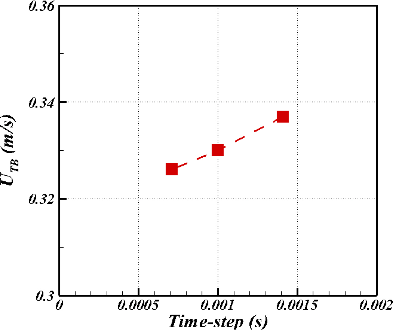
The same procedures were also performed for the time step uncertainty analysis of the simulations. Tables 3 and 4 provide details of the time step uncertainty analysis. The result also shows the monotonic convergence with Rk,T = 0.571 and time uncertainty with Uk,T = 1.21% (Fig. 3). Both the grid convergence test and time convergence test results were in the monotonic convergence range, and the uncertainty was below 5.00%. Therefore, the base mesh system was chosen, and the time step was set to 1.00 ×10⁻³ regarding the computational time and accuracy of the result.
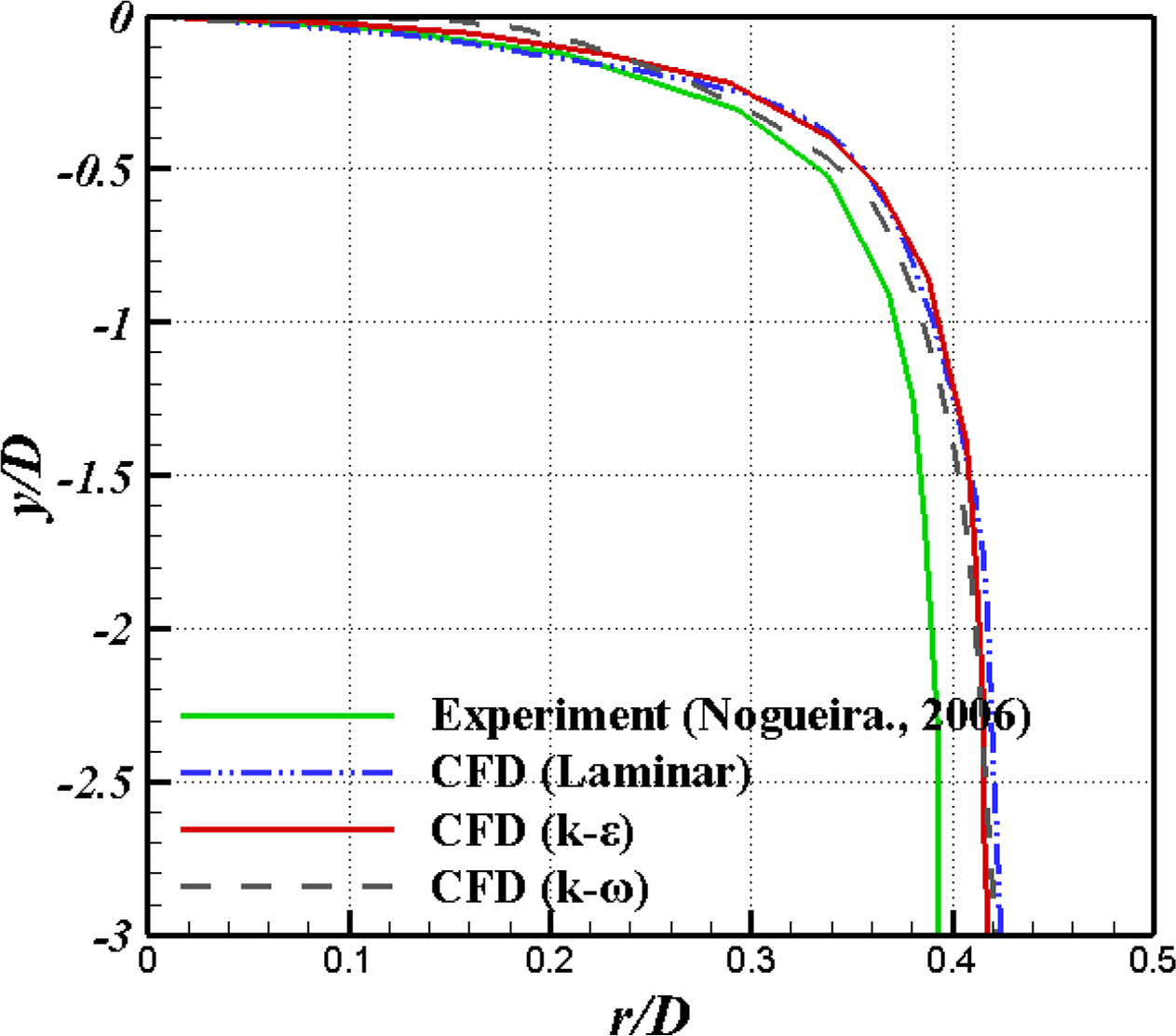
The flow in the present study was strictly a laminar-liquid and turbulent gas problem (Biberg, 2005). Therefore, the flow characteristics cannot be defined simply by the Reynolds number, such as single-phase flow. To study this type of flow, Naraigh et al. (2011) examined the effects of an interaction between the laminar liquid and turbulent gas in the interface using a physical model. On the other hand, this method is limited in the commercial program Star-CCM+. Therefore, the entire flow region was assumed to be turbulent flow based on fully-developed turbulent gas. Tables 5 and Fig. 4 compare the bubble characteristics in different turbulent models. The Realizable k−∊ model showed better agreement than the others. Therefore, the Realizable k−∊ was used in this study.
2.4 Validation
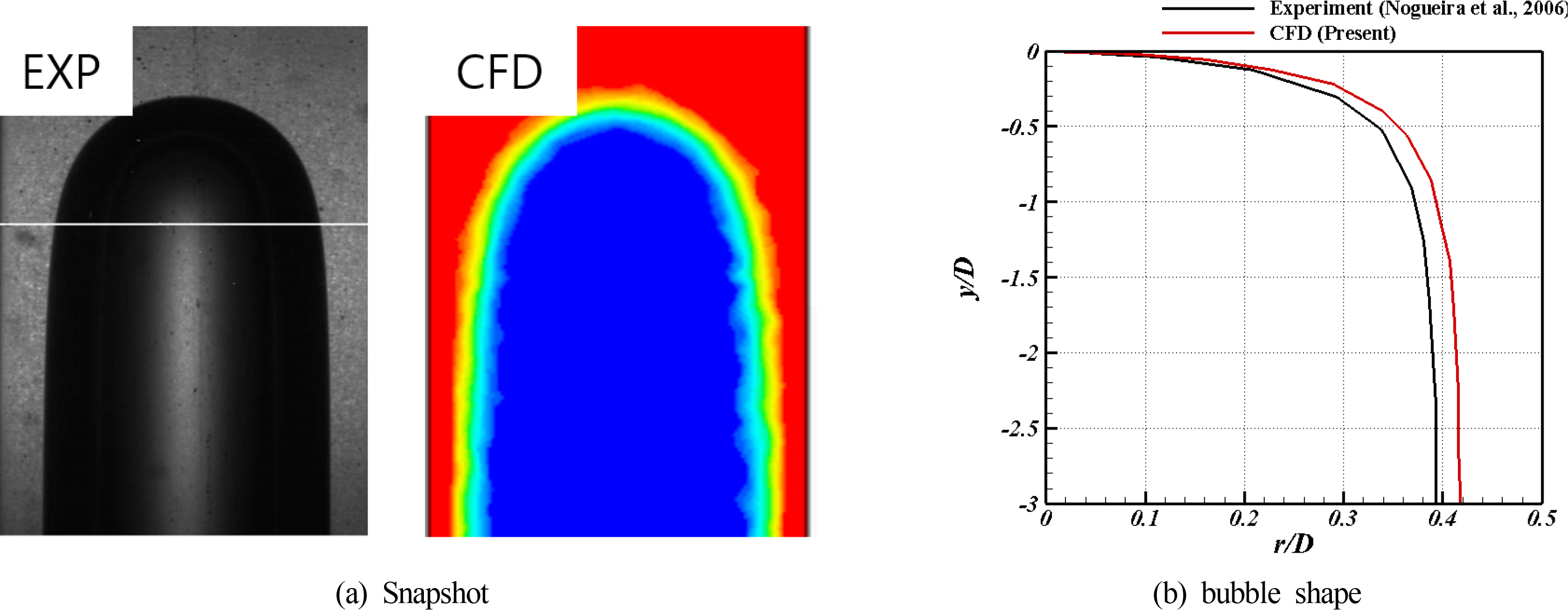
The simulation was validated by a comparison with the experimental results reported by Nogueira et al. (2006) on a single Taylor bubble rising in co-current flow conditions. The experimental condition corresponds to ReUTB = 325, Froud number (FrUTB)) = 0.68, and Eotvos number (Eo) = 167. Fig. 5 compares the simulation and the experimental result of the Taylor bubble shape and liquid film thickness;both are the main hydrodynamic features of the Taylor bubble mentioned by Araújo et al. (2012).
The present simulation agreed well with the bubble shape with a mean difference in the liquid film thickness of 4.11%. The simulation could predict the shape of a bubble with a reasonable liquid film thickness compared to the experimental results.
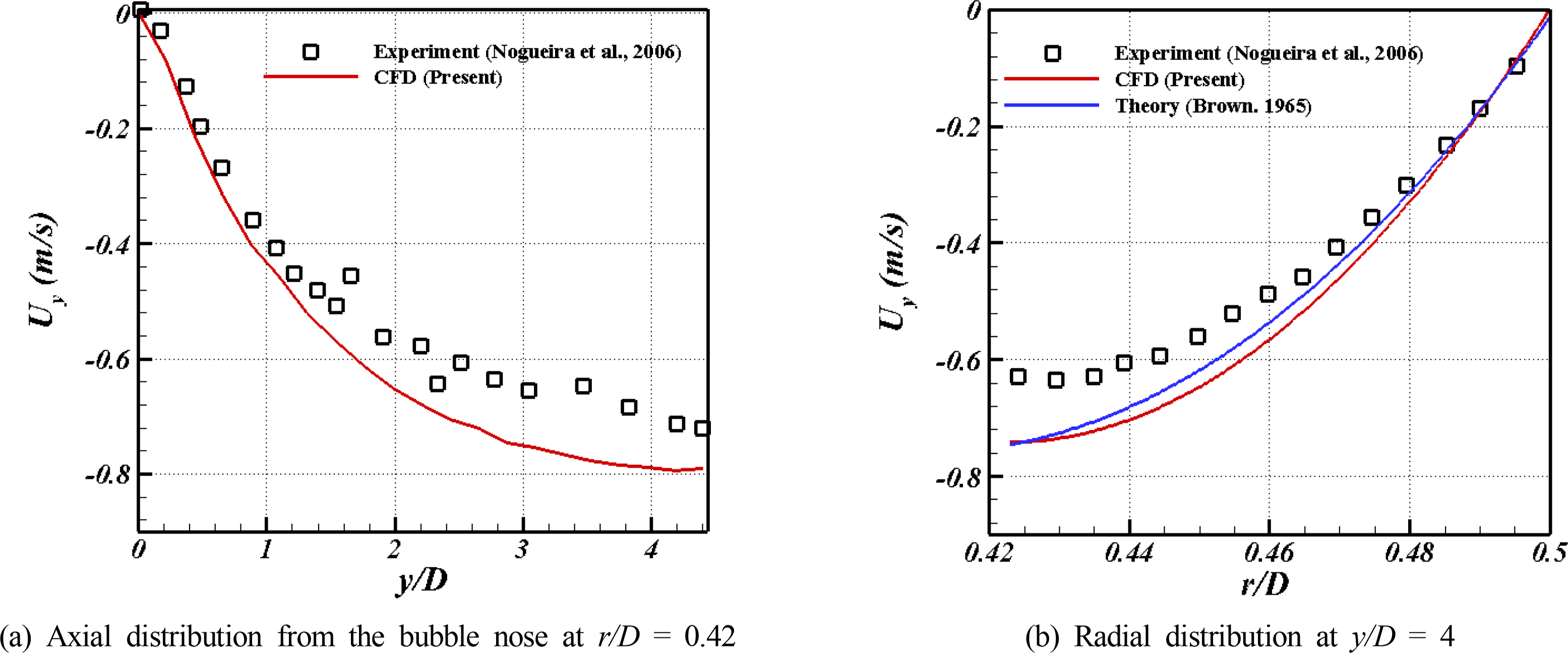
Fig. 6 shows the axial and radial distribution of the y-direction velocity in the liquid film, comparing the CFD results and experimental results. Fig. 6 presents acceptable matching between the CFD result and experimental result within a 10 % difference. The radial velocity distributions can be compared with the theoretical values suggested by Brown (1965), and the differences were much less than those with the experimental results because the PIV measurements usually have a high level of errors near the bubbles due to the diffraction of its laser sheet.
Furthermore, the bubble terminal velocity of the simulation was compared with the theoretical and experimental results, as shown in Table 6, with the respective deviation. Dumitrescu (1943) suggested a correlation for the bubble terminal velocity, which was developed by Nicklin et al. (1962) as Eqs. (9) and (10).
2.5 Case Study
In the present study, the first five cases were performed using the vertical pipe by changing the air injection velocity. The liquid velocity and air volume remained constant at 0.074 m/s and 3.06 × 10⁻⁴ m3, respectively, which are the same as the experimental data to investigate only the effects of the air injection velocity. The bending pipe was inevitable in the pipeline design for optimal space use under the limited design conditions. Therefore, the vertical pipe and the vertical to horizontal 90° bent pipe were investigated to examine the effects of geometry in the pipe. From Cases 6 to 10, the bent pipe was used to study the effect of geometry under the same conditions as the first five cases. In addition, the simulation considered the laminar, transient, and turbulent regimes by changing the water velocity while keeping the air injection velocity constant to compare the effect of the air injection velocity and the effect of the water velocity. Table 7 provides details of the simulation case.
3. Simulation Results
3.1 Slug Flow in a Vertical Pipe
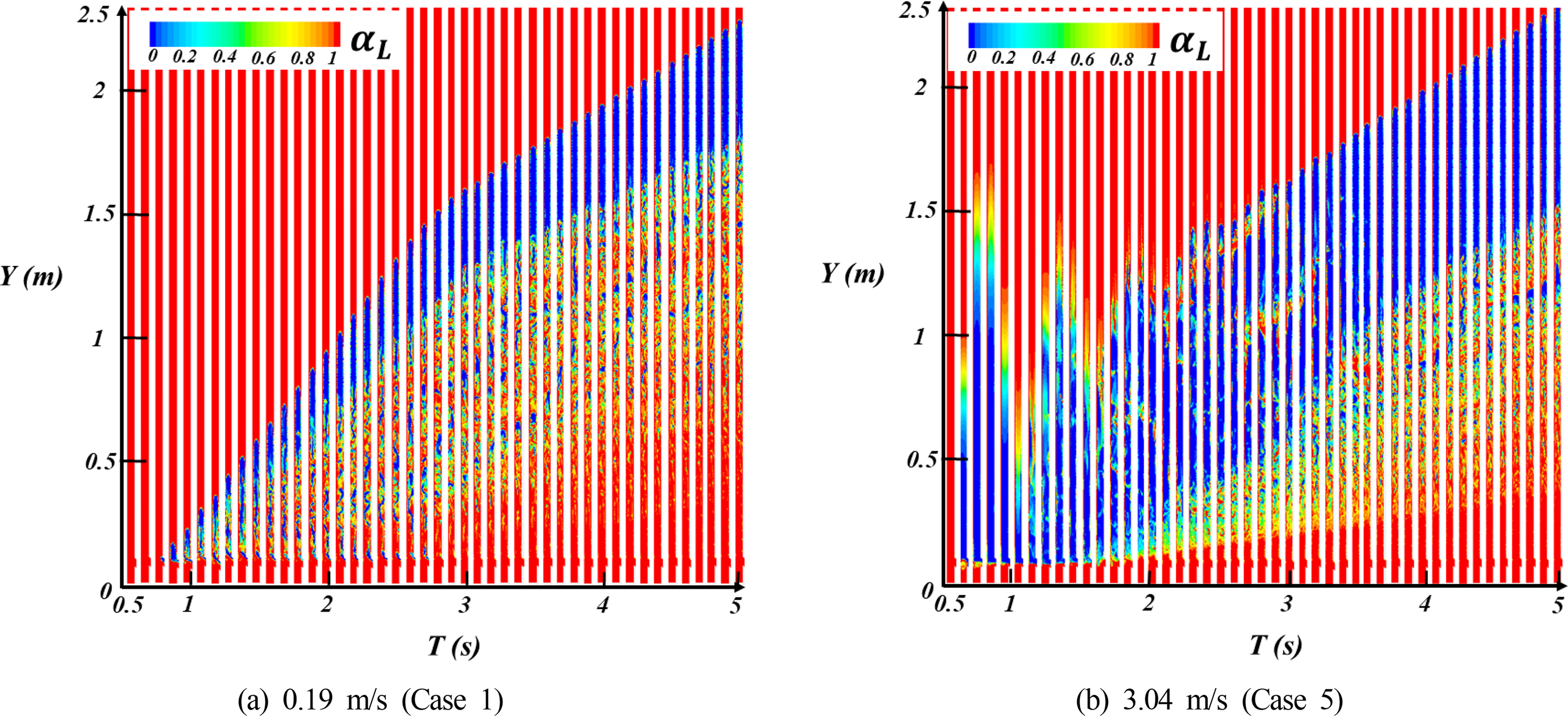
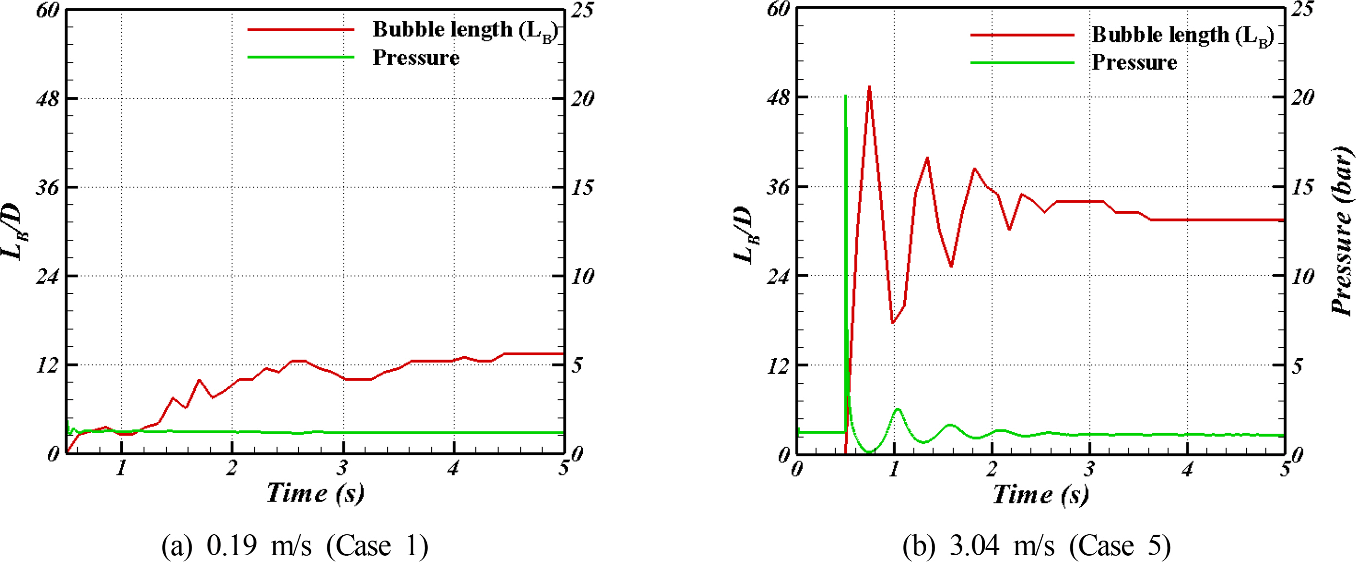
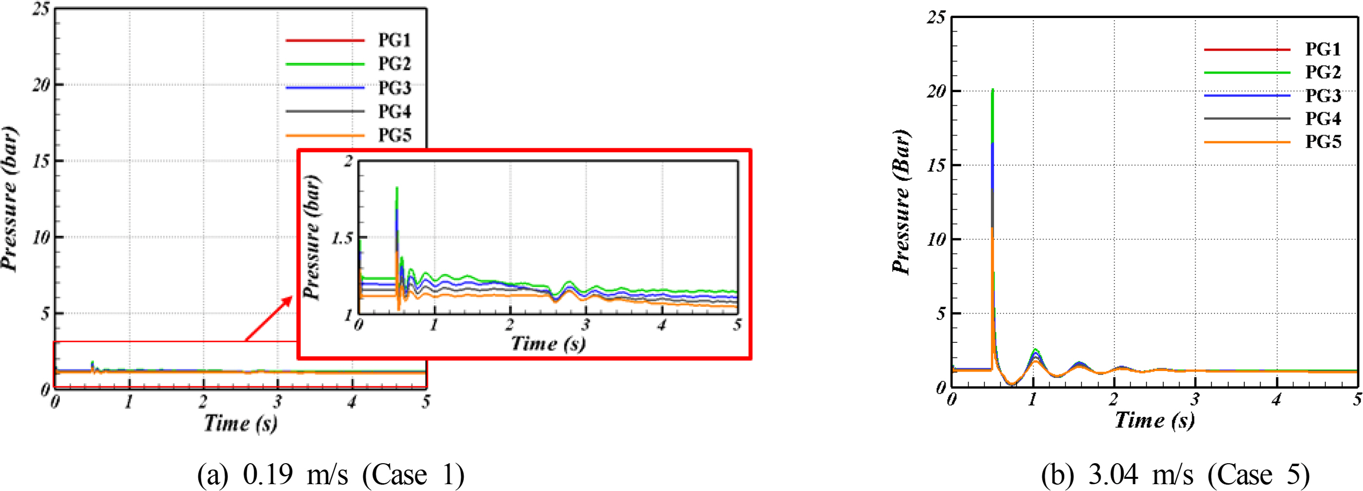
Fig. 7 presents snapshots of the VOF image, which was taken from 0.50 s to 5.00 s with a 0.10 s interval. Cases 1 and 5 were compared to show the difference in bubble behavior at different air injection velocities. The air injection velocity was 0.19 m/s and 3.04 m/s, respectively. In the relatively smaller air injection velocity of 0.19 m/s (Case 1), the air was compressed when the air is started to be injected, and the size of the bubble increased. In Case 5, however, which has a higher air injection velocity of 3.04 m/s, the air fluctuated with the injection and stabilized. The bubble behavior is described quantitatively as the length of the bubble and is shown in Fig. 8 with the pressure fluctuations at PG2. In Case 1, the bubble length barely changed during the simulation time, and the pressure fluctuations were small. In the Case 5, however, the bubble length initially changed dramatically then stabilized in 2.00 s. A peak pressure occurred at the moment air was first injected, followed by pressure vibrations. Therefore, the air injection velocity affects the bubble length, and it brings a change in pressure fluctuation in the pipe.
Fig. 9 compares the time history of the pressures with various measurement points for cases 1 and 5. The pressures showed the same behavior at various measurement positions with those different pressure magnitude. This means that air injection affects the entire region of the pipeline with different injection velocities. Furthermore, a high level of pressure fluctuations was observed in Case 5 because of its high injection velocity. The fluctuations were very small in Case 1, which had the smallest injection velocity.
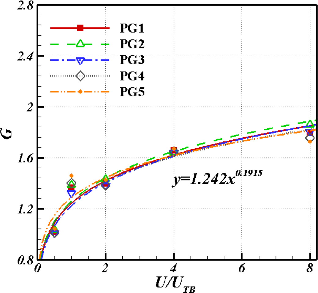
Fig. 10 presents the results of the peak pressure analysis. The figure shows the change in peak pressure as a function of the air injection velocity and the peak pressure in each location. The peak pressure in the vertical pipe increased linearly with increasing the air injection velocity (Fig. 10(a)). On the other hand, an opposite trend was observed when the peak pressure was normalized by the air injection velocity. Considering the movement of bubbles (Fig. 7), the peak pressure in the pipe was influenced greatly by the compression of air. When air is injected at a relatively slow flow rate, the air compresses and forms a Taylor bubble and shows a large peak pressure. At a fast flow rate, however, the air is dispersed and shows a small peak pressure, y. Fig. 10(c) shows the dimensionless peak pressure at different locations in each case. The peak pressure increased slightly from PG1 to PG2, and the largest peak pressure is shown in PG2, which decreases gradually from PG2 to PG5 in all cases.
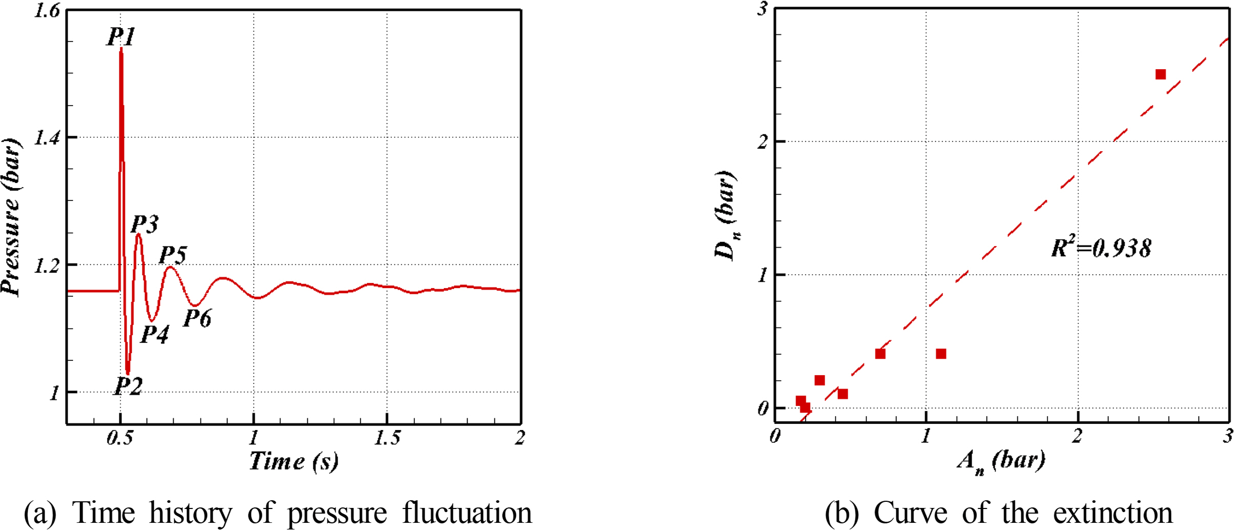
Fig. 11(a) presents the pressure fluctuations at 0.19 m/s of the air injection velocity as a time history. The pressure showed a peak at 0.50 s when air was injected first and decreased with time. The damping was similar to the roll damping for the ship lateral motion. To study this pressure damping, the roll damping coefficient was calculated using Eqs. (13) and (14):
Using Eqs. (13) and (14) with the successive positive peak and negative peak from the pressure data (Fig. 11(a)), the extinction curve was plotted, as shown in Fig. 11(b). At five different locations, the extinction curves were plotted by changing the air injection velocity.
As shown in Fig. 12, the gradient of the extinction curve increased with increasing air injection velocity. This means that the pressure fluctuations at a higher air injection velocity were damped faster than those at a lower air injection velocity. On the other hand, the gradient of the extinction curve was unaffected by the location. As described above, the method to calculate the roll-damping coefficient for ship lateral motion was applied to the pressure oscillation induced by the bubble in a pipe. Water appears to play an important role in damping the pressure.
3.2 Slug Flow in a Bent Pipe
As shown in Fig. 13, the peak pressure around the bent area at different air injection velocities was studied. The normalized peak pressure, as the pressure coefficient in the bent pipe, decreased with increasing distance from the inlet. This trend weakened as the air injection velocity increased. Although it was expected that the peak pressure difference between PG7 and PG8 was due to the gravitational force, the difference was not noted in terms of the peak pressure. The lack of an apparent difference between PG7 and PG8 might due to the hydrostatic pressure becoming negligible because of high peak pressure.
The peak pressure analysis in the bent pipe was also conducted and compared with the peak pressure in the vertical pipe. As shown in Fig. 14 (a), the peak pressure in the bent pipe increased with increasing air injection velocity in the same manner of the vertical pipe. Similarly, the peak pressure in the bent pipe was nominalized by air injection velocity. The dimensionless peak pressure in the bent pipe decreased more dramatically than that in the vertical pipe as the air injection velocity increased. The largest peak pressure in the bent pipe was 1.5 times higher than that in the vertical pipe. The highest peak pressure in the bent pipe occurred in PG1’ and decreased with increasing distance from the inlet to the pressure gauge.
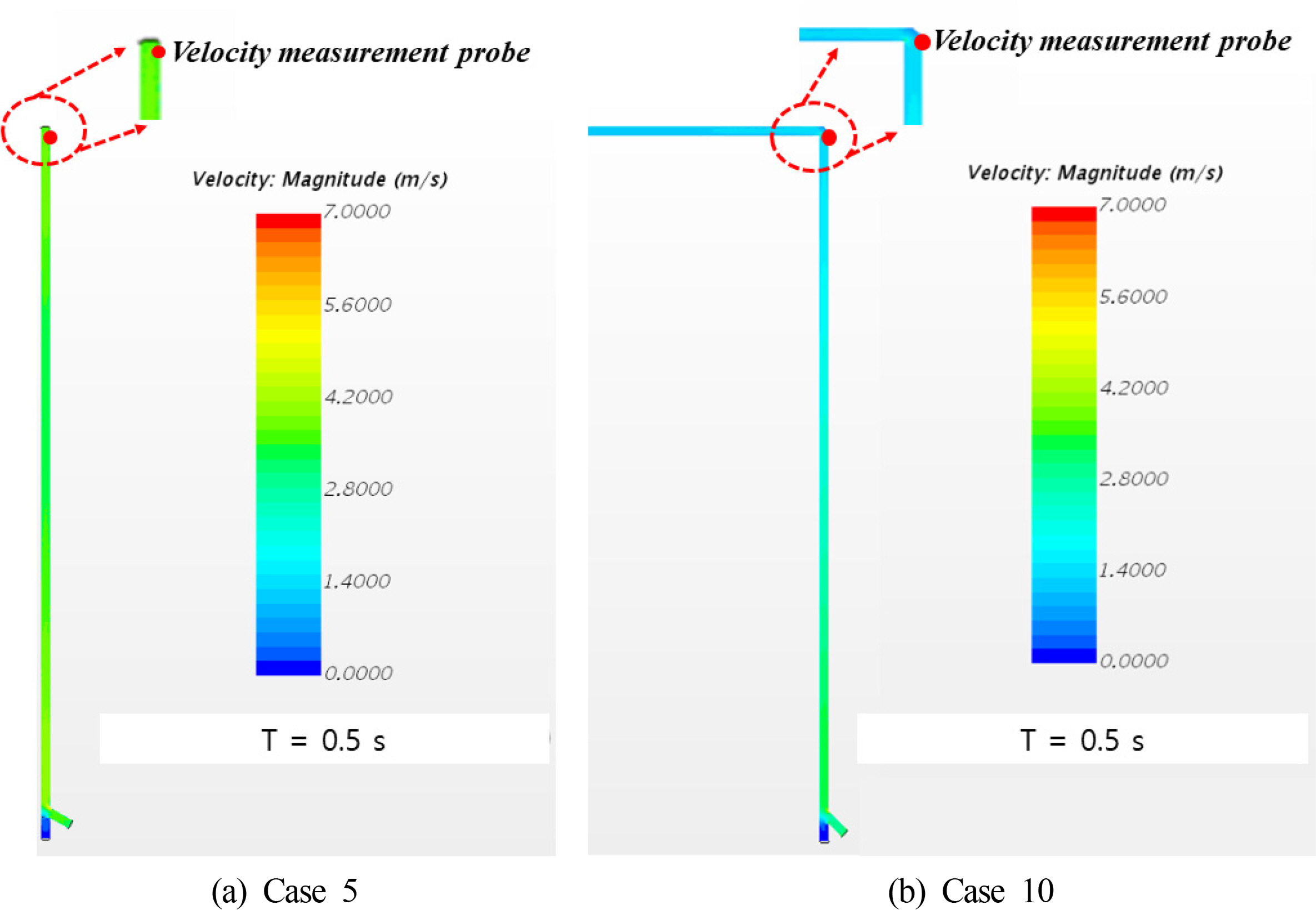
Fig. 15 shows the velocity field of the vertical pipe and bent pipe. When the air was injected, the fluid was stuck at the bend, and instantaneously, a stagnant point that could not be seen in the bent pipe was formed. The velocity was monitored, where the stagnant point was formed in the bent pipe, and the vertical pipe was also monitored at the same location as the one in the bent pipe. Fig. 16 shows the time histories of the velocity at the measurement probe shown in Fig. 15 for Cases 5 and 10. Note that the measurement point for the vertical pipe was 2.4 m away from the inlet and that for the bent pipe was 2.5 m to avoid simulation errors near the pressure outlet. As shown in Fig. 16, the velocity at 0.50 s, when the peak pressure occurs in the vertical pipe, was 4.40 m/s, but the velocity at 0.50 s in the bent pipe was 1.20 m/s. The flow in the bent pipe was slower than that in the vertical pipe, which means that the fluid does not flow properly in the bent pipe. In addition, the velocity in the bent pipe became instantaneously zero when the peak pressure occurred, but there was no point where the velocity became zero in the vertical pipe at 0.50 s. This can explain why the peak pressure in the bent pipe was higher than that in the vertical pipe.
3.3 Effect of Water Velocity
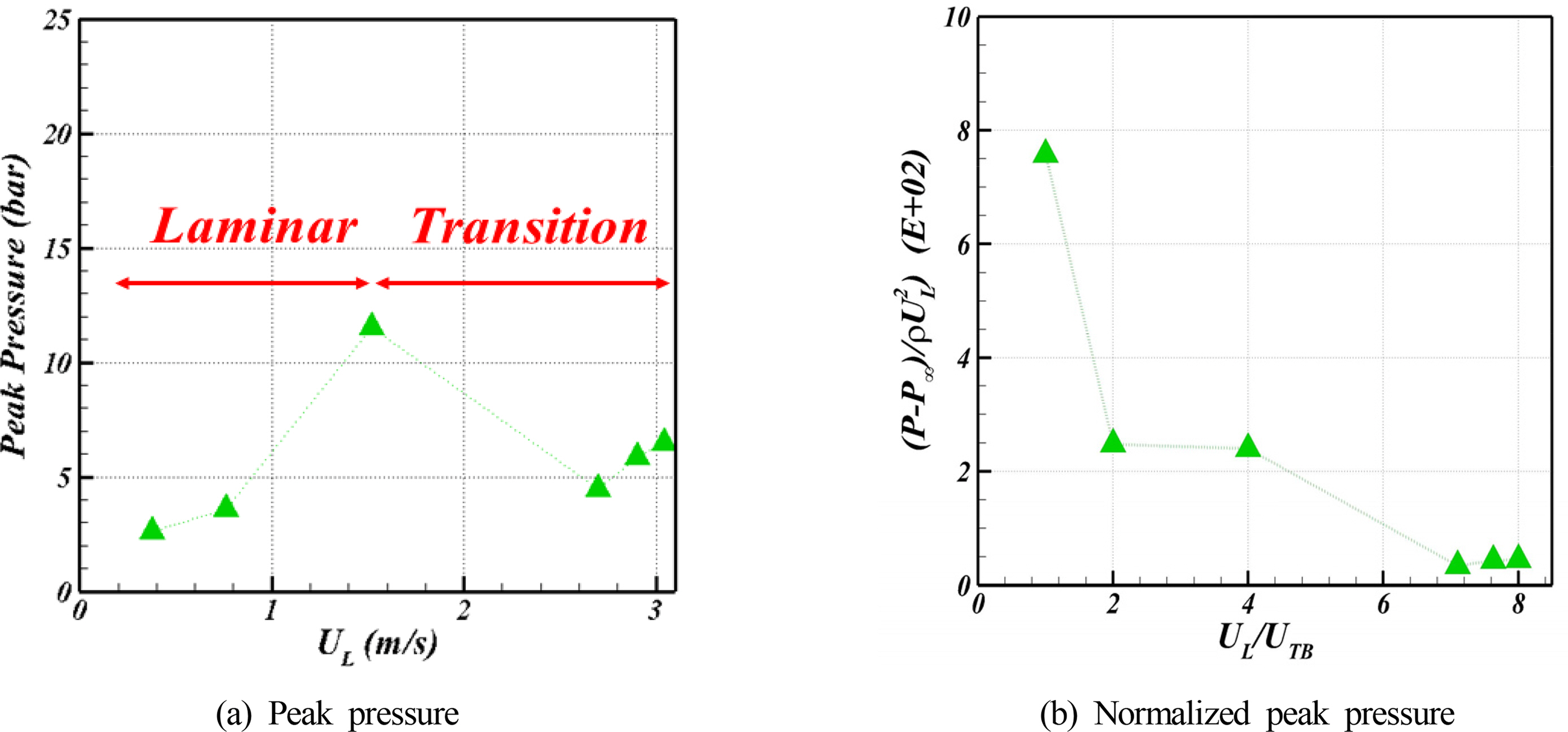
The effect of the water velocity on the peak pressure in a pipe was investigated by measuring the peak pressure in the bent pipe after changing the water velocity from 0.38 m/s to 3.00 m/s at a fixed air injection. While the peak pressure increased with increasing air injection velocity, the peak pressure increased linearly with increasing water velocity until the water velocity reached to 1.52 m/s, but it decreased after water velocity was more than 1.52 m/s and started to rise slightly at 2.70 m/s and reached the peak pressure, even though the water velocity increased after 3 m/s, as shown in Fig. 17(a). The linear increase region was under the laminar flow. Moreover, the peak pressure of the transient region was irregular, and the region where the peak pressure maintained a certain level was turbulent. When the peak pressure was normalized as the pressure coefficient (Fig. 17(b)), a similar trend was observed for all water flow regimes when the air velocity was changed as the pressure coefficient decreased with increasing water velocity. This means that the compressibility of air is also affected by the water velocity, and its effect is higher when the flow velocity is relatively small.
4. Conclusion
In the present study, the pressures induced by the slug flow in the pipeline were investigated numerically using Star-CCM+. The vertical and bent pipes were considered for various air and water injection velocities. The simulation setups were tested by changing the mesh size and time step based on the GCI method. The simulations were validated with experimental and theoretical data with good agreement for the main hydrodynamic characteristics of a Taylor bubble, i.e., the bubble shape, bubble terminal velocity, and liquid film velocity. The slug flow simulations were conducted by varying the air injection velocity from 0.19 m/s to 3.04 m/s and water velocity from 0.38 to 3.04 to investigate the effects of the bubble on the pressures in the pipeline. The key findings are summarized as follows.
The peak pressures were observed when the air was injected into the pipeline, and pressure oscillations were followed by fluctuations of the bubble length. The pressure oscillations occurred due to the compressibility of air, and the magnitude increased for high air injection velocities. Furthermore, the pressure oscillations showed the same trend for all the measurement positions because the bubbles affect the entire region of the pipeline.
The peak pressure showed the maximum at the PG2, which was located 20D from the inlet, and it increases with increasing air injection velocity. An opposite trend was shown after normalizing the pressure to the pressure coefficient using the air injection velocity. This means that the peak pressure is strongly affected at lower air injection velocities, because the bubbles can be compressed more at those velocities.
The pressure damping in the vertical pipe was investigated using the method to calculate the roll damping coefficient for the lateral motion of a ship. Damping is stronger at higher air injection velocities, while the distance from the inlet did not affect pressure damping.
When the pipe had a bend, the peak pressure showed a 1.5 times larger magnitude than that in the vertical pipeline in the same air and water injection velocity. The water has a stagnant point at the corner of the bend and causes more air compression in the bent pipe.
The compressibility of the air was also affected by the water velocity, and its effect was higher when the flow velocity was relatively small, showing a similar trend to the air injection velocity. The change in peak pressure with various water velocities was linear when the flow regime was laminar, but it fluctuated when the water velocity increased.
Overall, bends in pipes where slug flow is expected should be minimized in the pipeline design stage because a bent pipe is more vulnerable to slug flow than a vertical one. These findings are based on a simple pipeline geometry, and it can provide useful data for other experimental studies. Nevertheless, further studies on pipeline system design considering slug flow will be needed.
Notes
This study was supported by the R&D Platform Establishment of Eco-Friendly Hydrogen Propulsion Ship Program (No. 20006636), PNU Korea-UK Global Graduate Program in Offshore Engineering (N0001288), and Global Advanced Engineer Education Program for Future Ocean Structures (P0012646) funded by the Ministry of Trade, Industry & Energy (MOTIE, Korea), and the National Research Foundation of Korea (NRF) grant funded by the Ministry of Science and ICT (MSIT, Korea) through GCRC-SOP (No. 2011-0030013).

