1. Introduction
Simulation-driven design is one of the most important methods for ship optimization. With the development of computer-aided design technology, research on hull shape optimization through computer simulation has gradually been applied to design more energy-efficient and environmentally friendly ships. In the preliminary design stage, it is very important to optimize the hydrodynamic characteristics of the hull form. As computers speed up and memory grows, researchers are experimenting more with Computer Aided Design (CAD) and simulation (CFD) methods.
Due to the complex geometry shape of a ship's hull, it is difficult to use numerical methods to describe it. Therefore, researchers often choose to modify the hull form by making changes to a basic design. Lackenby (1950) developed a method to modify a hull by controlling the position of the center of buoyancy and shifting the section curves. Since then, the Lackenby method has been widely used in hull modification.
In recent years, there have mainly been two popular ways of modifying a bulbous bow geometry: parametric modeling and the Free-Form Deformation (FFD) method. Chrismianto and Kim (2014) used a Cubic Bezier curve and curve-plan intersection methods to generate a parametric bulbous bow. Luo and Lan (2017) used a B-Spline curve and NURBS curve to generate a parametric bulbous bow in the CAD-CFD integration platform CAESES. Plug-in software called Grasshopper was used to generate a parametric bulbous bow from a few vertexes and NURBS curves.
The wave-making resistance of a ship hull depends largely on the bow part (the area between the stem and mid-ship). It is efficient to optimize the bow part of a ship to reduce the wave-making resistance. The bulbous bow and the hull between the bulbous bow and mid-ship are two main parameters to optimize.
Different governing equations are used in a CFD solver to predict a ship hull’s hydrodynamic performance. One of the most popular methods is the Reynolds averaged Navier-Stokes (RANS) method. Zhang et al. (2018) used the RANS method to calculate the total resistance in an optimization framework (Park et al., 2019; Kim et al., 2019). Usually, hundreds of simulations are carried out in an optimization process, and the hydrodynamic performance prediction can be quite a time consuming. Researchers have tried different ways to reduce the computing time. Han et al. (2012) selected a non-linear potential flow using the Rankine panel method to predict trim and sink during a simulation. Kostas et al. (2015) used the Neumann-Kelvin formulation and the boundary element method (BEM) to simulate the wave-making resistance.
Many kinds of optimization equations have been used to find an optimal solution quickly and accurately. Zhang et al. (2018) used the Particle Swarm Optimization (PSO) algorithm to help find an optimal bulbous bow. Huang et al. (2016) implemented a “new improved Artificial Bee Colony” (NIABC) algorithm in KCS hull optimization. Gammon implemented a Multi-Objective Genetic Algorithm (MOGA) in the optimization of a fishing vessel, and the optimization equations showed high accuracy and efficiency.
In this study, the wave-making resistance of a catamaran in calm water was selected as the objective function for optimization. The length, breadth, and angle of the bulbous bow were modified by the FFD method and then optimized by the Non-dominated Sorting Genetic Algorithm (NSGA)-II. The bow part was optimized by simulating nine different hull forms that were modified by the Lackenby method and then comparing them. Finally, after obtaining the optimal demi-hull, the distance between two demi-hulls was optimized.
2. Demi-hull Geometry Modification Method
2.1 Bulbous Bow Modification
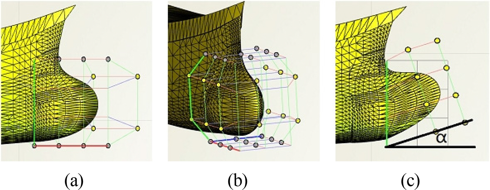
The FFD and Lackenby methods were applied to modify the hull geometry. The bulbous bow area begins from station No. 20, and it was modified in three dimensions: the length, breadth, and its angle with the baseline. Fig. 1 shows how the FFD method is applied to the bulbous bow. The bulbous bow shape is modified by a control box with certain control points on it (Tomas and Scott, 1986). The bulbous bow angle α is defined in Fig. 1c as the angle between the base line and the rotated control box. The clockwise direction is defined as positive, and the anticlockwise direction is defined as negative.
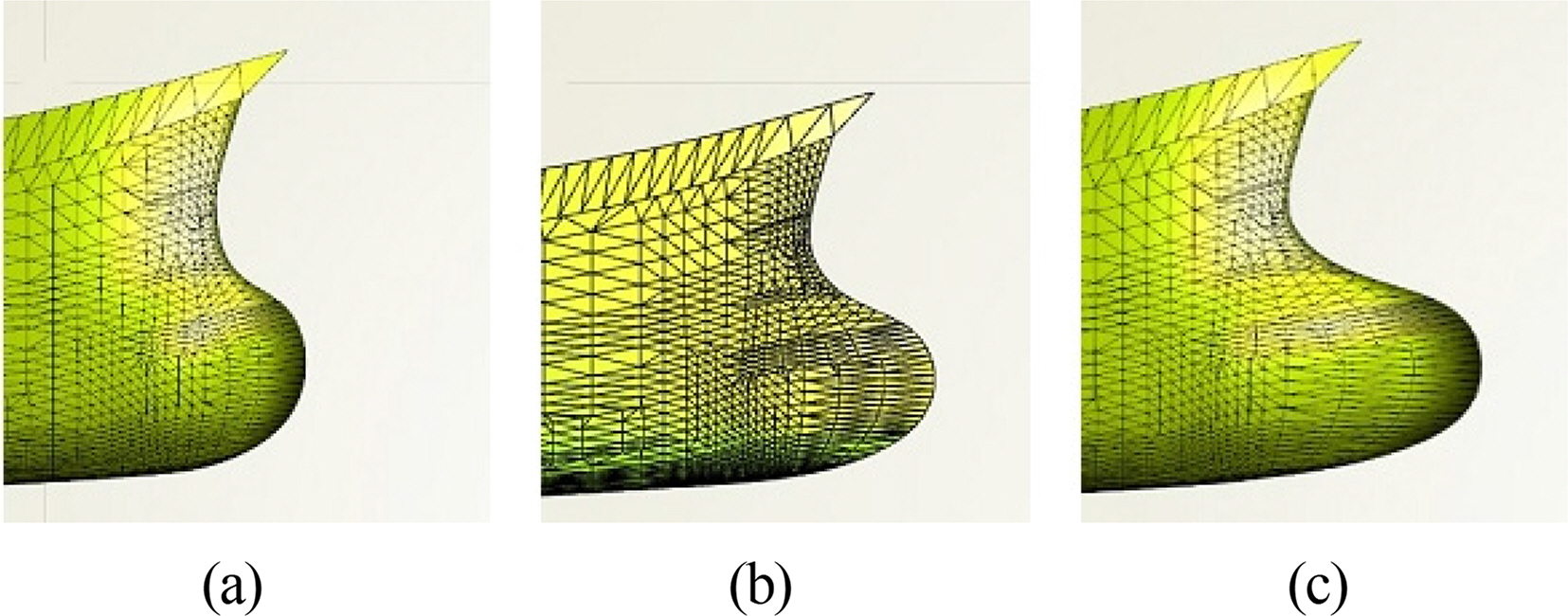
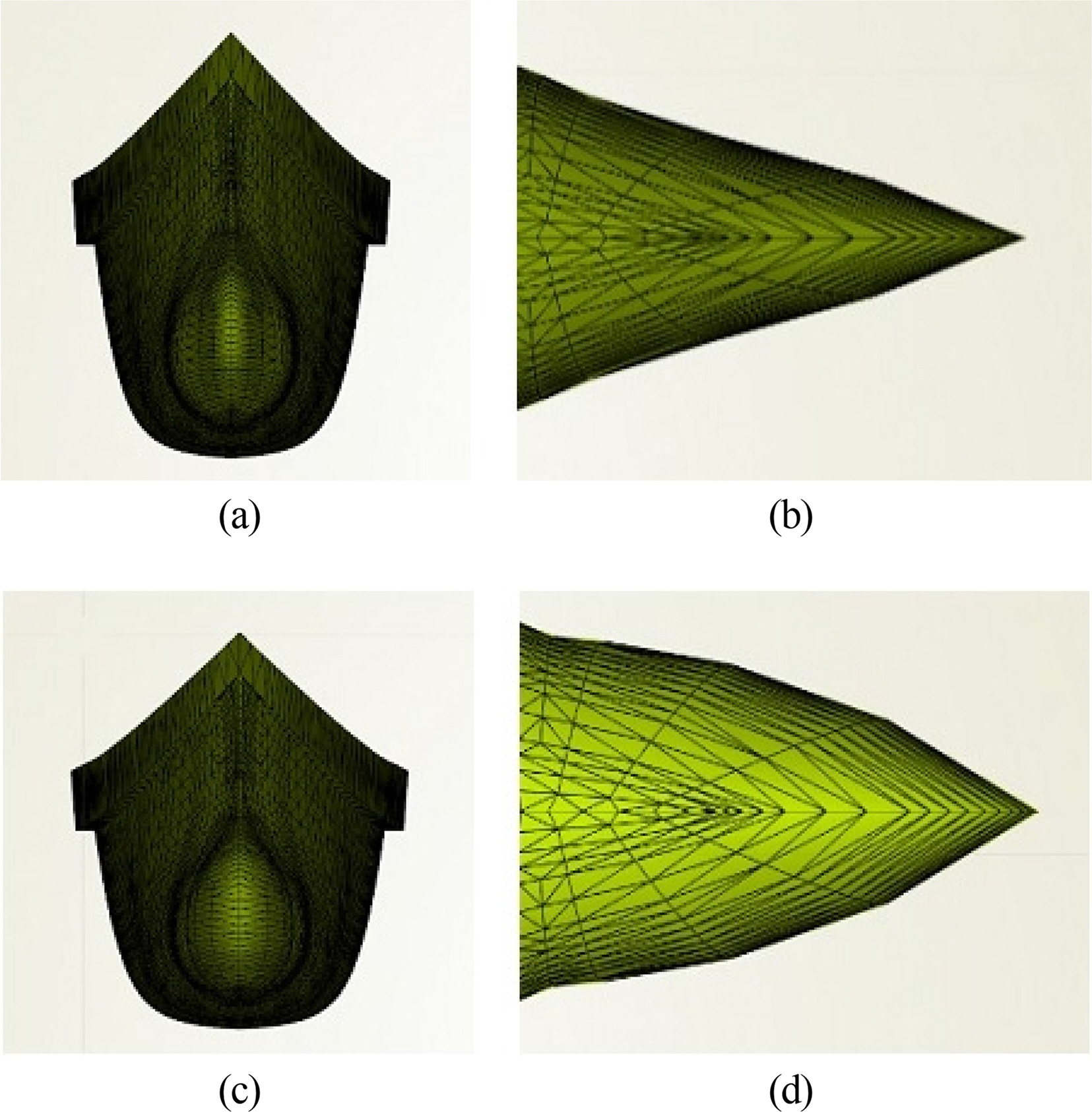
Fig. 2 shows the length of the bulbous bow modified under the constraint of −0.02LOA ≤ ΔL ≤ 0.02LOA, where ΔL is the change of length of the bulbous bow, and LOA is the overall length. Fig. 3 shows the breadth of the bow modified under the constraint of 0.8B ≤ B’ ≤ 1.3B, where B is the original breadth of the bow, and B’ is the breadth of the new bow. Fig. 4 shows the angle of the bow modified under the constraint of −9° ≤ α ≤ 3°, where α is the difference from the original angle.
2.2 Bow Part Modification
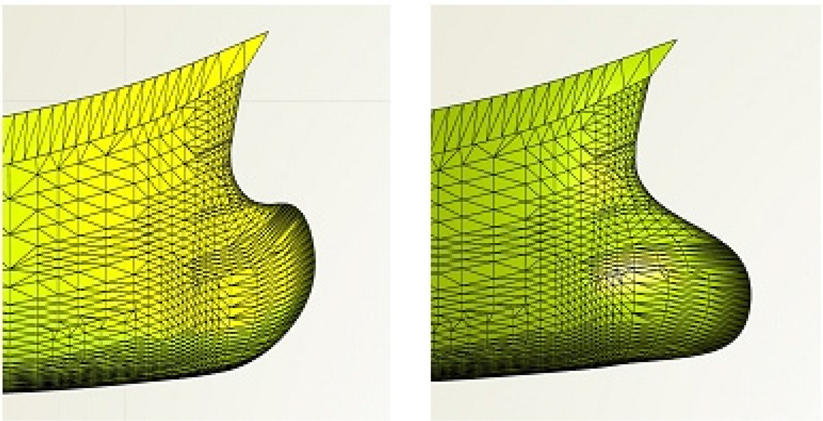
The bow part is the part of the hull between the bulbous bow and mid-ship. The Lackenby method was used for the bow part modification. The longitudinal center of buoyancy (LCB) was changed slightly while the displacement was kept constant. The change in LCB (ΔLCB) was set as a design variable. Fig. 5 shows the bow part modified by moving the LCB by ±0.4%. The inflection point of the original sectional area curve was located around station 16, so this station was set to be the modification center.
3. Numerical Calculation by STAR-CCM+
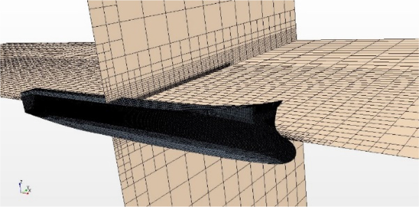
A high-speed catamaran was selected as an example for optimization, and its main data are shown in Table 1. The high-speed catamaran travels with a high Froude number (i.e., Fn > 0.3). In this case, the viscous resistance is usually a smaller proportion of the total resistance, and the contribution of the bow part to the viscous resistance is negligible. Therefore, optimizing the resistance in an inviscid fluid is an effective way to optimize the performance of the high-speed ship. STAR-CCM+ was selected to perform the numerical simulation and evaluation, and the fluid model was set as an inviscid fluid model.
4. Software Integration and Demi-hull Optimization
4.1 Bulbous Bow Optimization
The resistance was simulated in STAR-CCM+ and fed back to CAESES by coupling the two programs. The FFD method was used to modify the bulbous bow shape with the design variables: the length, breadth, and angle. NSGA-II was then used to obtain the optimal bulbous bow.
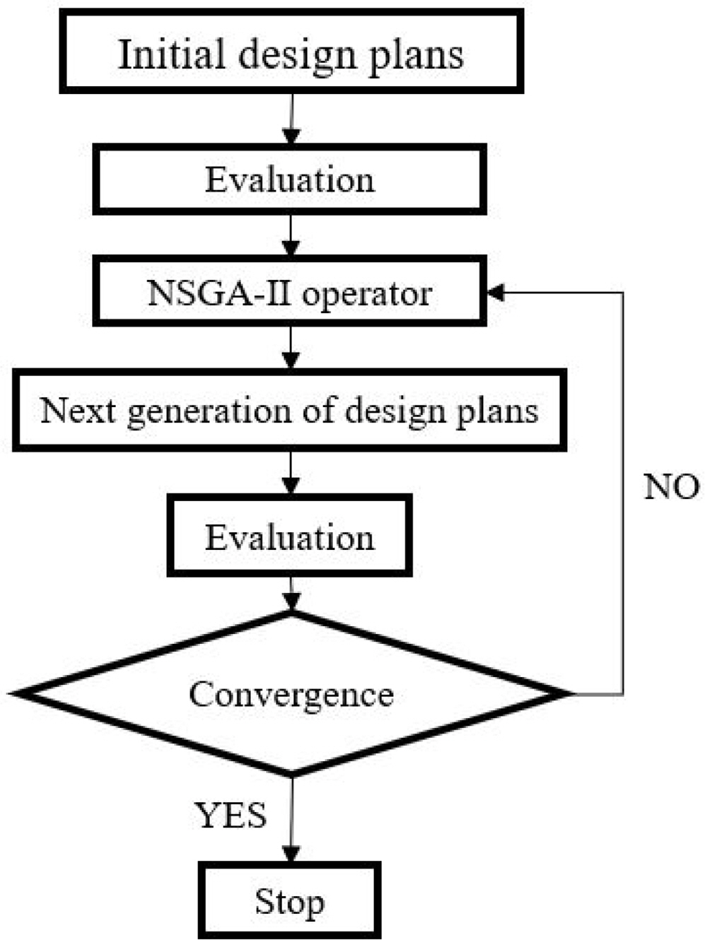
Fig. 7 shows a flow chart of the NSGA-II process for the design variables of the bulbous bow. Firstly, 27 initial design plans were generated by changing the bulbous bow length, breadth, and angle defined by the FFD method as the first generation. 27 simulations were then carried out in STAR-CCM+ to obtain the resistance results. The plans that performed well were selected to mutate and crossover to obtain the next generation.. New generations of hull plans were simulated and selected again and again until the resistance results converged.
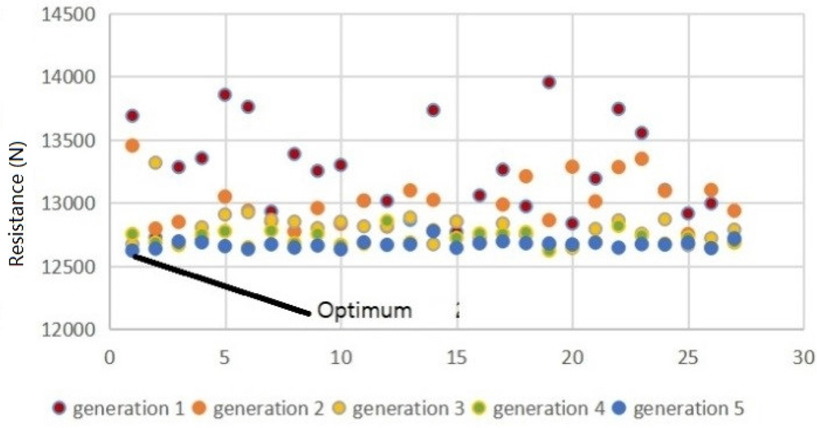
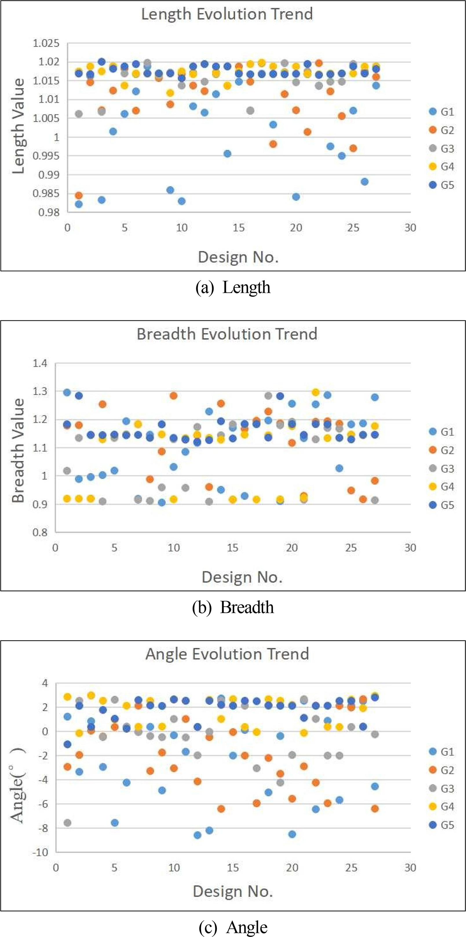
Fig. 8 shows the resistance results of the inviscid fluid after 5 generations of different bulbous bow plans. The results are from 135 simulations carried out by STAR-CCM+. The noted point represents the optimal solution. Fig. 9 shows the evolution of the length, breadth, and angle. It can be seen that the length converges to 1.018, the breadth converges to 1.14, and the angle converges to 2.64°.
4.2 Bow Part Optimization
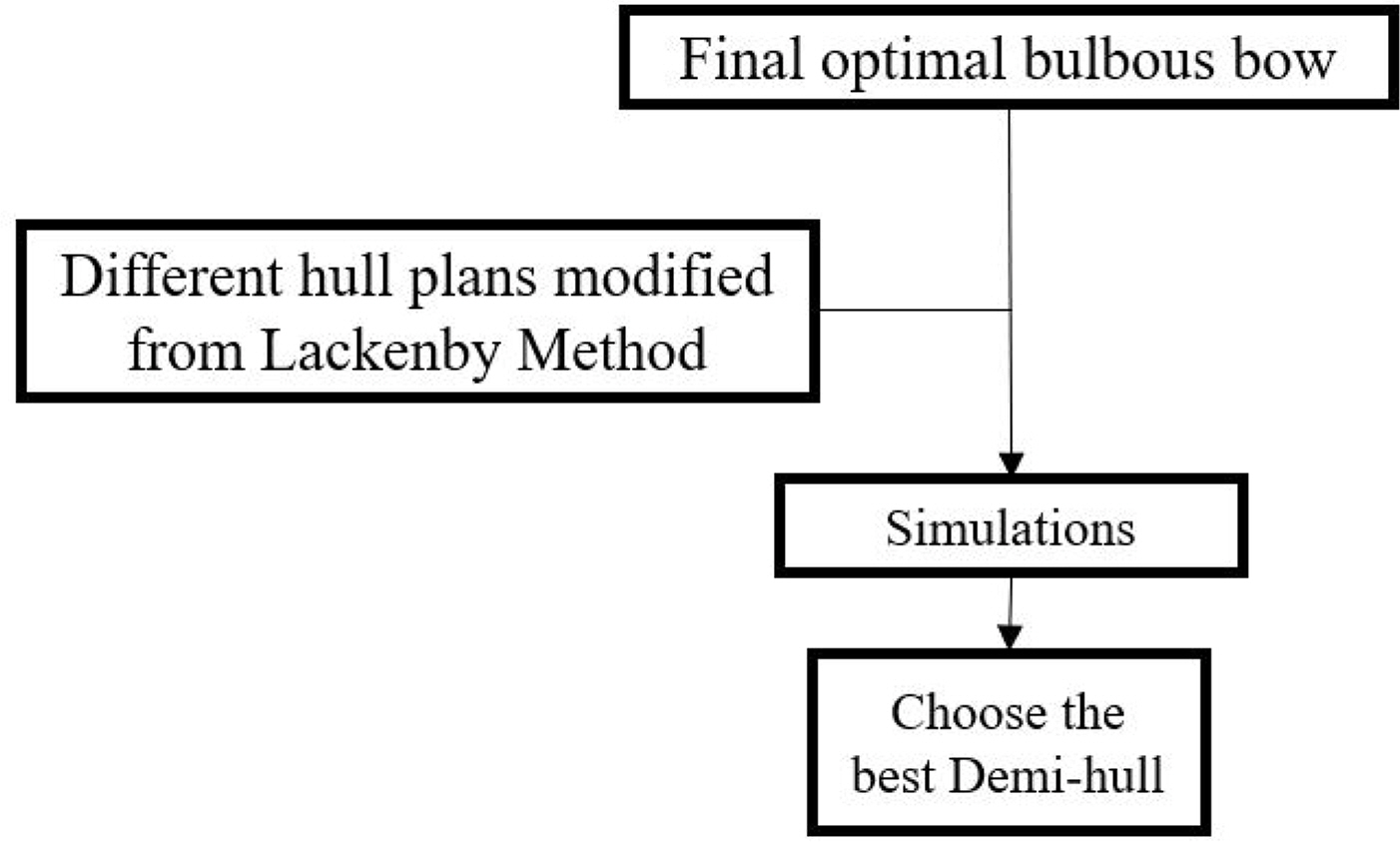
The bow part was modified by using the Lackenby method to shift the section curve, and the design variable was ΔLCB. A total of 9 different plans from the Lackenby method were computed, and the optimized demi-hull form was obtained. Fig. 10 shows a flow chart of choosing the optimal demi-hull.
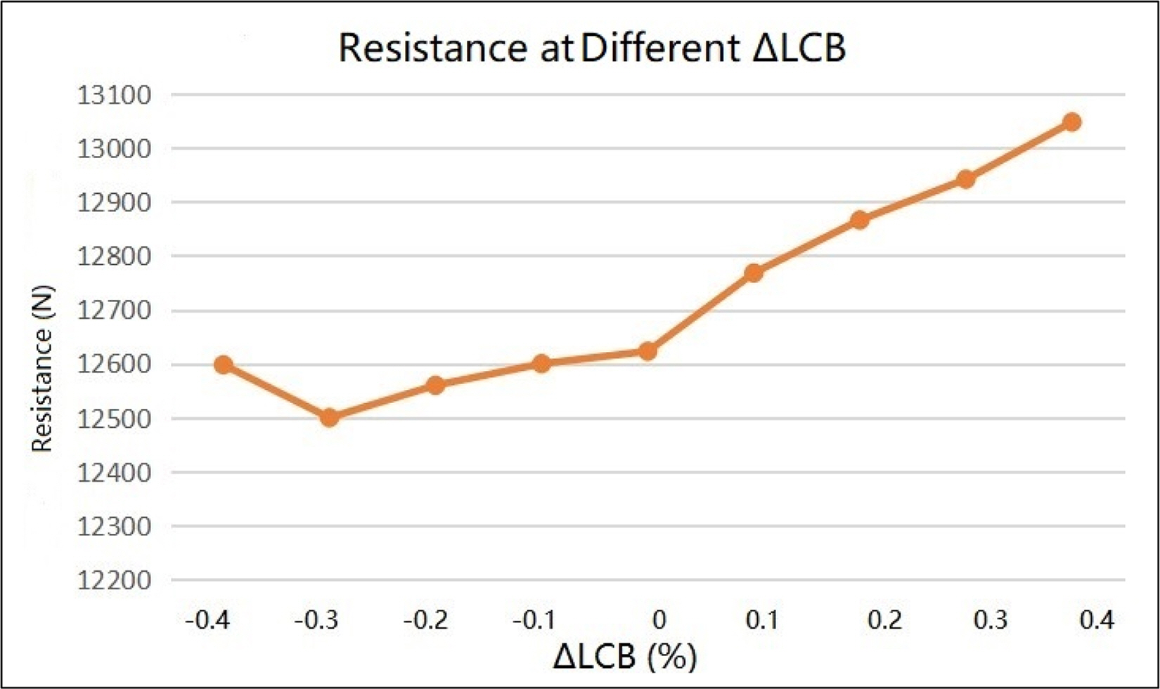
Fig. 11 shows the simulation results of the 9 different hull forms from the Lackenby method. The results show that the resistance was reduced by about 1% when the longitudinal center of buoyancy was moved backward by 0.3%.
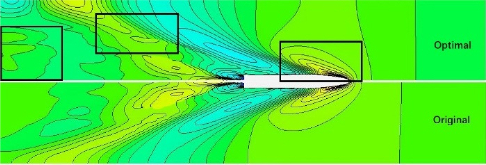
The wave pattern comparison is shown in Fig. 12. The 3 main differences are pointed out with 3 black squares. The wave pattern at the bow of the optimal demi-hull is smaller, and the wave pattern in the far field of the optimal demi-hull is lower than the original one.
5. Optimization of Distance Between Demi-hulls
According to Millward (1992), the effect on the resistance coefficient is separated into three parts. The effect of the distance has no rules to follow when Fn is in the range of around 0.2 to 0.4. In the Fn range of 0.4 to 0.7, the distance between the demi-hulls has a positive correlation with the total wave-making resistance. When the distance between the demi-hulls is larger, the negative interference of the two demi-hulls is weaker. When Fn is beyond 0.7, the 2 lines of the resistance coefficient begin to cross, which means the effect of the distance also has no rules to follow. However, we do know that there is a potential optimal distance.
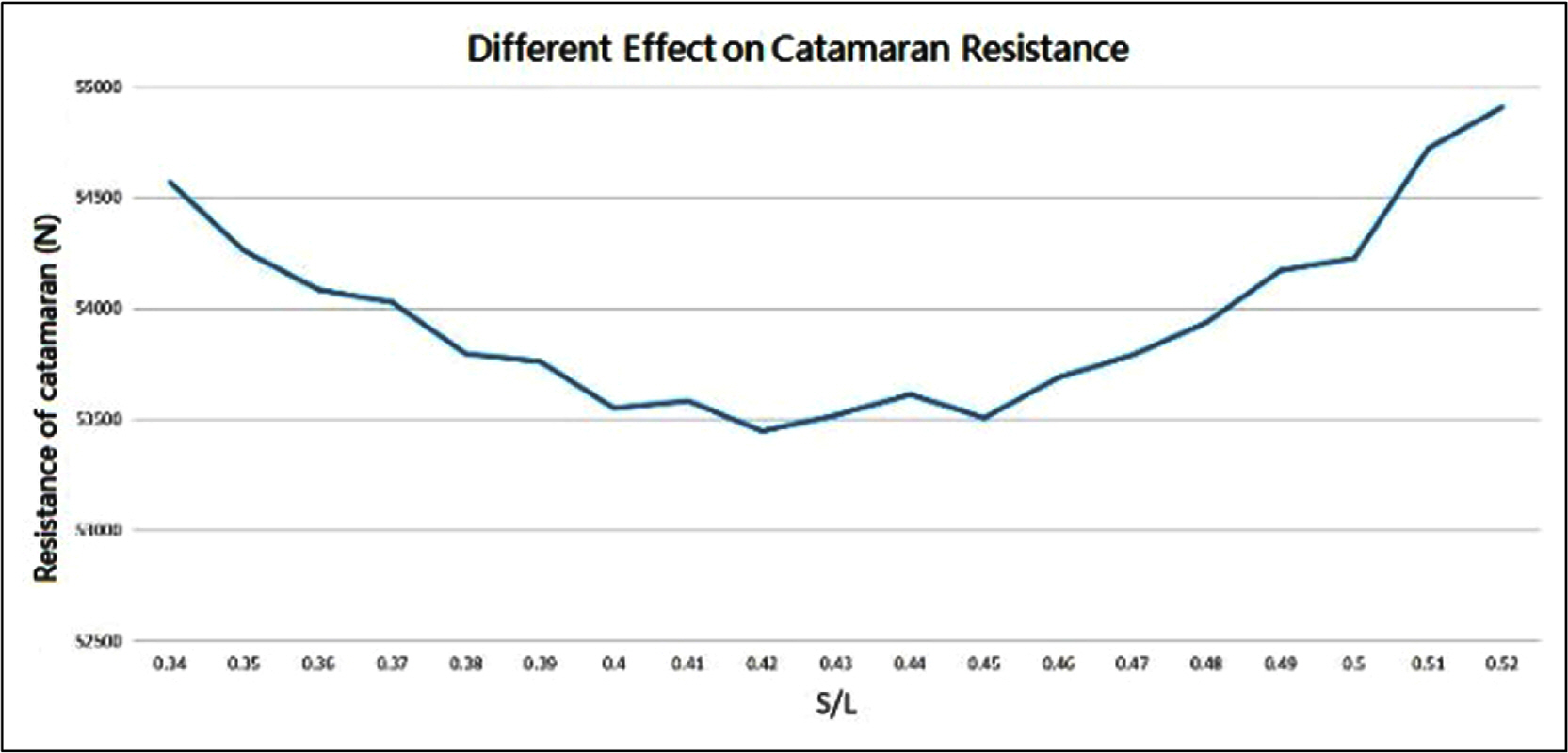
With the design speed of the catamaran (Fn=0.73), 19 different cases of separation between the two demi-hulls were generated and simulated. The results are shown in Fig. 13. The resistance of the catamaran is smallest when S/L is 0.42. This means the optimal distance of the two demi-hulls is 8.4 m. S is the distance between the two demi-hulls, and L is the length of the catamaran. The results show that the distance between the demi-hulls of the catamaran does have an optimal value in this case.
6. Conclusion
The hull form of a high-speed catamaran was optimized by coupling the software CAESES and STAR-CCM+. The resistance simulation was carried out using the RANS method, and the fluid model was set to inviscid to reduce the computing time. The bulbous bow of the demi-hull was optimized by a genetic algorithm, and the forms were generated by the FFD method for various lengths, breadths, and angles. The bow part between the bulbous bow and the mid-ship was then optimized by simulating 9 different hull forms that were modified by the Lackenby method while keeping the displacement of the demi-hull constant. The design variable was ΔLCB. The distance between the two demi-hulls was then optimized by simulating 19 different separation cases.
The wave-making resistance of the optimal demi-hull was reduced by 6.2% compared to the original demi-hull. The total resistance of the catamaran had optimal performance when the distance between the two demi-hulls was 8.4 m (S/L=0.42). The results showed that this optimization loop is feasible and efficient. The NSGA-II algorithm was used for only the bulbous bow optimization, and the bow part was optimized independently. However, the bulbous bow and the bow part affect each other. Future work will focus on optimizing the bulbous bow and bow part of the hull together to find the best combination of the two parts.


