J. Ocean Eng. Technol. Search

CLOSE


J. Ocean Eng. Technol. > Volume 34(3); 2020 > Article
Park and Choung: Punching Fracture Experiments and Simulations of Unstiffened and Stiffened Panels for Ships and Offshore Structures

Abstract

Ductile fracture prediction is critical for the reasonable damage extent assessment of ships and offshore structures subjected to accidental loads, such as ship collisions and groundings. A fracture model combining the Hosford-Coulomb ductile fracture model with the domain of solid-to-shell equivalence model (HC-SDDE), was used in fracture simulations based on shell elements for the punching fracture experiments of unstiffened and stiffened panels. The flow stress and ductile fracture characteristics of JIS G3131 SPHC steel were identified through tension tests for flat bar, notched tension bar, central hole tension bar, plane strain tension bar, and pure shear bar specimens. Punching fracture tests for unstiffened and stiffened panels are conducted to validate the presented HC-DSSE model. The calibrated fracture model is implemented in a user-defined material subroutine. The force-indentation curves and final damage extents obtained from the simulations are compared with experimental results. The HC-DSSE fracture model provides reasonable estimations in terms of force-indentation paths and residual damage extents.

Nomenclature

A, ε0, n: Material parameters of Swift constitutive model

a, b, c, nf: Hosford-Coulomb model parameters

D: Damage indicator

DHC: Damage indicator of Hosford-Coulomb model

DDSSE: Damage indicator of DSSE model

d: Dimension

i: Number of experiments for fracture model calibration

I: Identity tensor

I1: First invariant of stress tensor

J2: Second invariant of the deviatoric stress tenso

J3: Third invariant of the deviatoric stress tensor

le: Length of element

R: Residual error

s: Deviatoric part of stress tensor

t: Thickness of specimen

f1, f2 , f3: Function of Lode angle parameters

g1, g2: Function of stress triaxaility

d, p: DSSE model parameter

k: Flow stress

η: Stress triaxiality

θ̄: Lode angle parameter

ε̄p: Equivalent plastic strain

ɛ¯HCpr : Fracture strain of Hosford-Coulomb model

ɛ¯DSSEpr : Fracture strain of localization necking criterion

ɛ¯DSSEPST : Strain at the onset of localization under plane strain tension

ε̄p,f : Fracture strain

α: Least square error function

ε̄plat: End of yield plateau

σ: Caucy stress tensor

σm: Mean stress

σ̄: von Mises stress

1. Introduction

In accidental scenarios related to ships and offshore structures that involve contact, such as collision and grounding, large deformation and fracture may occur occasionally. Damage assessment based on the numerical analysis of an accident can reduce the cost of physical experiments and reduce human, social, and environmental damages through the design of a structure that effectively responds to the accident load. Mild and high-tensile strength steels primarily used in the shipbuilding and offshore industry are considered as ductile materials. Therefore, information regarding the plasticity and fracture behavior of these steels is essential for an accurate structural behavior prediction through the numerical analysis of shipbuilding and offshore structures as well as material experiments.
In a phenomenological model, fracture initiation is defined as the point at which the damage indicator, which is expressed in terms of stress or strain, reaches a threshold. Researchers have used phenomenological models with stress triaxiality and lode angle as stress state parameters to predict ductile material failure (Johnson and Cook, 1985; Xue, 2007; Bai and Wierzbicki, 2008; Choung et al., 2015a; Choung at al., 2015b; Park et al., 2017; Cerik et al., 2019c; Park et al., 2019a; Park et al., 2020). Bai and Wierzbicki (2010) developed the modified Mohr–Coulomb model expressed by stress triaxiality and Lode angle parameter. Mohr and Marcadet (2015) proposed a Hosford–Coulomb (HC) fracture strain model expressed in terms of Mohr–Coulomb failure condition and the Hosford equivalent stress. The Mohr–Coulomb yield criterion-based fracture strain model has been demonstrated through theoretical/experimental studies to simulate the fracture prediction of ductile materials with high accuracy (Roth and Mohr, 2016; Algarni et al., 2017; Cerik et al., 2019a; Park et al., 2019b).
Researchers have attempted to quantitatively measure the extent of damage through failure tests on unstiffened/stiffened panels that are typically used in marine structures (Choung and Cho, 2008; Min and Cho, 2012; Park et al., 2016; Cho et al., 2018; Nho et al., 2018; Cerik et al., 2019b). Although plastic deformation problems accompanied by large strains such as impact and stranding generate complex loads, such as compression, shear, bending, and tension, the major damage mode is caused in the tensile region owing to the continued deformation of the thin-walled shell structure. In this tensile mode damage, localized necking usually occurs, resulting in a local thickness reduction. In other words, the stress state at the point where the local necking occurs changes from a plane stress to a triaxial stress. To accurately predict the local necking, fine solid element meshing is essential. Meanwhile, to reduce computational cost and enhance the simplicity of modeling, use of a shell element is inevitable. However, the existing phenomenological models significantly reduces the accuracy of fracture prediction in shell-element-based numerical analyses (Pack and Mohr, 2017; Park et al., 2019a; Cerik and Choung, 2020). Recently, researchers have attempted to improve the fracture prediction accuracy of a shell-element-based numerical analysis such that it is comparable to that of a solid-element-based numerical analysis. Pack and Mohr (2017) presented a domain of solid-to-shell equivalence (DSSE) model, where the thickness direction necking of a plate was defined as a fracture condition in the shell-element-based fracture simulation.
This study aims to obtain the plasticity and fracture behavior characteristics data of JIS G3131 SPHC, which is a thin structural steel material, and to perform a quantitative verification of the fracture model presented through structural experiments. Swift hardening law and HC–DSSE model material constants were obtained through tensile tests and numerical analysis of specimens of various fracture modes (flat bar, notched tension, central hole, plane strain, and pure shear). A user subroutine was developed to apply the proposed fracture model as a fracture criterion for the commercial finite element program, Abaqus/Explicit. The quantitative verification of the proposed fracture model was performed by comparing the punching experiment of unstiffened/stiffened panels and the fracture stimulation.

2. Theoretical Background

2.1 Stress State Variable

The stress state of an isotropic material can be represented by the stress triaxiality (η) and Lode angle parameter (θ̄), which are expressed in terms of the stress invariant (Eqs. (1)(2)). The stress triaxiality and lode angle are expressed in terms of the first invariant (I1) of the stress tensor (σ) and the second invariant (J2) and third invariant (J3) of the deviatoric stress tensor (s) (Eqs. (3)(6)). The range of the Lode angle parameter is −1.0 ≦ θ̄≦ 1.0. The relationship between the stress triaxiality and Lode angle parameteris given in Eq. (7), and it can be represented in the plane stress state, as shown in Fig. 1.
(1)
η=I133J2=σmσ¯
(2)
θ¯=1-2πarccos[332J3(J2)3/2]=1-2πarccos[272J3σ3¯]
(3)
I1=tr[σ]
(4)
J2=12s:s
(5)
J3=det[s]
(6)
s=σ=-13I1I=σ-σmI
(7)
θ¯=1-2πarccos[272η(η2-13)]

2.2 Fracture Model for Three-dimensional Stress State

Mohr and Marcadet (2015) presented the Hosford-Coulomb (HC) model as a fracture criterion for ductile materials and structures in a three-dimensional stress state under a proportional loading. In the HC model, the constant stress state parameter, ( ɛ¯HCpr) is giben as function of stress state parameters {η, θ̄} and depends on material constants {a, b, c, nf} (Eq. (8)). Under proportional loading, if the equivalent plastic strain (ε̄p) reaches the fracture strain, it is assumed that fracture has occurred. Roth and Mohr (2016) suggested nf = 0.1 for general steel. Therefore, only material constants a, b, and c need to be determined in the HC model. The material constants a and c of the HC model represent the sensitivities of the stress triaxiality and Lode angle parameter, respectively. The material constant b determines the overall level of the fracture strain. Because the HC model has a small number of material constants, the material constants can be derived through a small number of experiments. Furthermore, the accuracy of the fracture prediction for ductile materials has been demonstrated and used by many researchers. On the other hand, a fracture model needs to consider the variability of the loading path during the deformation of materials and structures. Hence, a linear damage accumulation model, which is expressed as the accumulation of equivalent plastic strains, was used (Eq. (12)). In the accumulative damage model, failure occurs when the damage indicator (D) reaches 1.0.
(8)
ɛ¯HCpr(η,θ¯)=b(1+c)1nf({12([(f1-f2)a+(f1-f3)a+(f2-f3)a])}1a+c(2η+f1+f3))-1nf
(9)
f1=23cos(π6(1-θ¯))
(10)
f2=23cos(π6(3+θ¯))
(11)
f3=-23cos(π6(1+θ¯))
(12)
D=0ɛ¯pfdɛ¯pɛ¯HCpr

2.3 Fracture Model for Plane Stress States

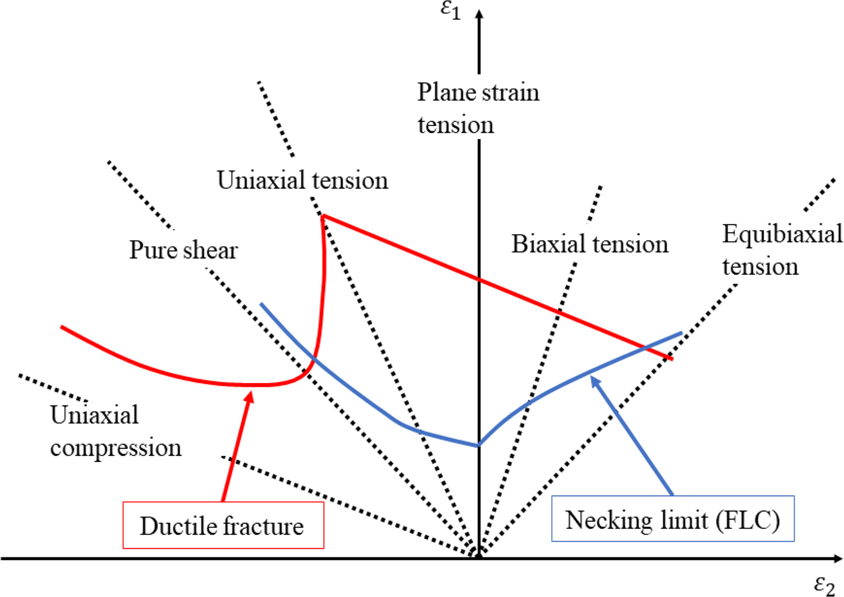
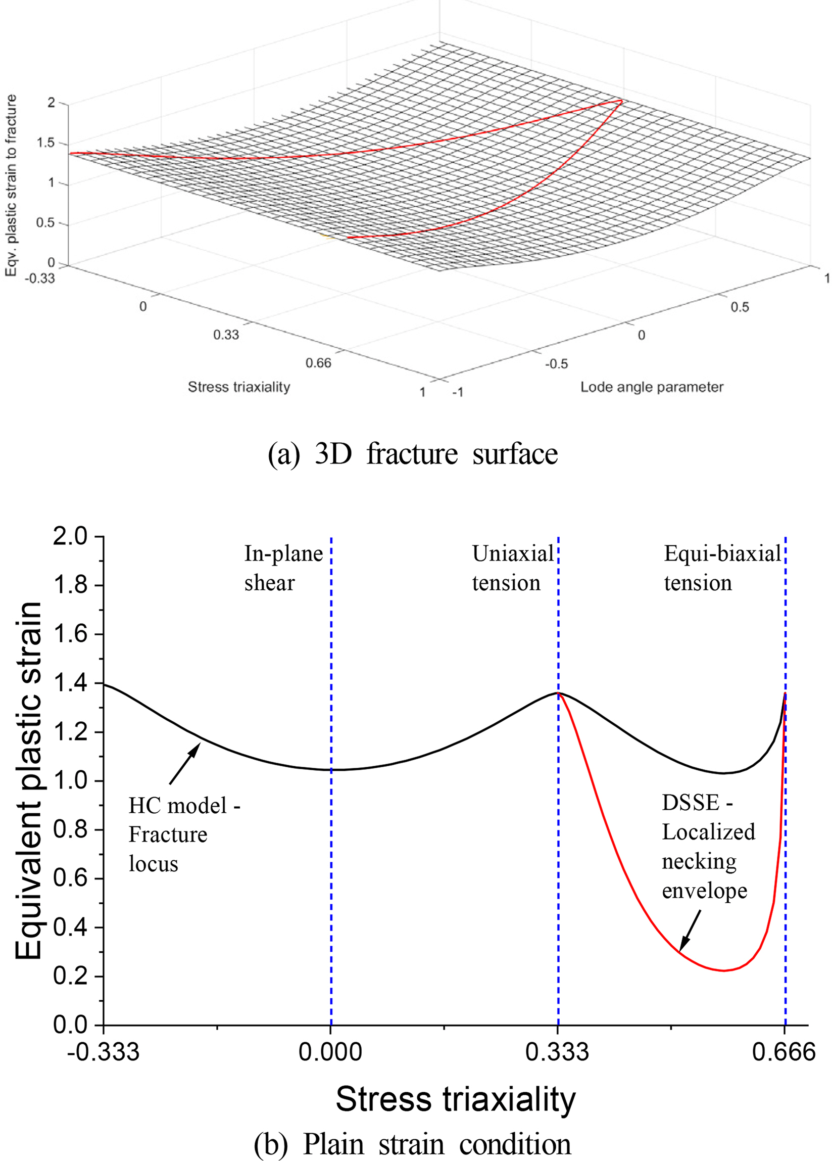
Ships and offshore structures are typical thin-walled shell structures, and shell-element-based modeling for the numerical analysis of these structures is essential for reducing time and simplifying modeling. The classical equivalent plastic-strain-based fracture model including the HC model shows a significantly reduced fracture prediction accuracy in shell-element-based fracture simulations. Pack and Mohr (2017) presented a DSSE model as a fracture criterion for plane stress states through the Marciniak–Kuczynski (MK) analysis of a unit-size shell element model. The MK analysis is primarily used to theoretically derive the forming limit curve of a material to avoid molding defects (necking, fracture, etc.) in the plate forming process. Therefore, the DSSE model considers the thickness direction necking to be a fracture criterion based on assuming that the difference between the local necking in the thickness direction and the point of occurrence of fracture is small based through MK analysis. In this study, for the fracture criterion in the shell-element-based fracture simulation, as shown in Fig. 2, the ductile fracture criterion (HC model) and the necking limit criterion (DSSE model) were applied. The application range of the DSSE model was (1/3≦η≦2/3) for the biaxial tension regime, and the DSSE fracture strain ( ɛ¯DSSEpr) comprised the stress triaxiality and material constants b, d, and p, as shown in Eq. (13). The material constant b was used in the HC model as well. Park and Mohr (2017) presented the DSSE model material constant p = 0.01 for ordinary steel through MK analysis. Therefore, only material constant d remained in the DSSE model.
Park and Mohr (2017) presented a Considère-assumption-based simplified equation to derive the material constant d of the DSSE model. In the Considère assumption, necking is defined as a plastic instability phenomenon. The flow stress ( k[ɛ¯DSSEPST]) at the local necking plastic strain ( ɛ¯DSSEPST) in the plane strain tensile (PST) state is shown in Eq. (16). Substituting the plane strain tensile state ( η=1/3) into Eq. (13) yields Equation (17), which can be solved through numerical iterations. The linear damage accumulation model of the DSSE is expressed as Eq. (18).
(13)
ɛ¯DSSEpr=b[{12((g1-g2)d+g1d+g2d)}1d]-1p}
(14)
g1=32η+13-34η2
(15)
g2=32η-13-34η2
(16)
k[ɛ¯DSSEPST]=23dk[ɛ¯DSSEPST]dɛ¯p
(17)
(1+2d-1)1d=3(ɛ¯DSSEPSTb)-p
(18)
D=0ɛ¯pfdɛ¯pɛ¯DSSEpr

3. Obtaining Fracture Model Material Constants

3.1 Material Experiment

3.1.1 Steel type

Plates are primarily used in the manufacture of marine structures. Generally, a thick steel plate of thickness 6 mm or more is used as a laboratory specimen. In some cases, structural experiments are conducted using scale model of double hulls (Ehlers et al., 2008; Ringsberg et al., 2018; Cerik et al., 2019b), but large structural experiments are subject to constraints (experimental equipment capacity, cost issues, etc.). In this study, owing to these practical limitations, a damage evaluation study was conducted through a structural experiment of a unstiffened/stiffened panels of a JIS G3131 SPHC hot-rolled thin plate with a thickness of 1.9 mm. The width of the target steel base plate was 1,530 mm, and the chemical composition is shown in Table 1. The longitudinal direction of the plate material was defined as a rolling direction.

3.1.2 Tensile tests

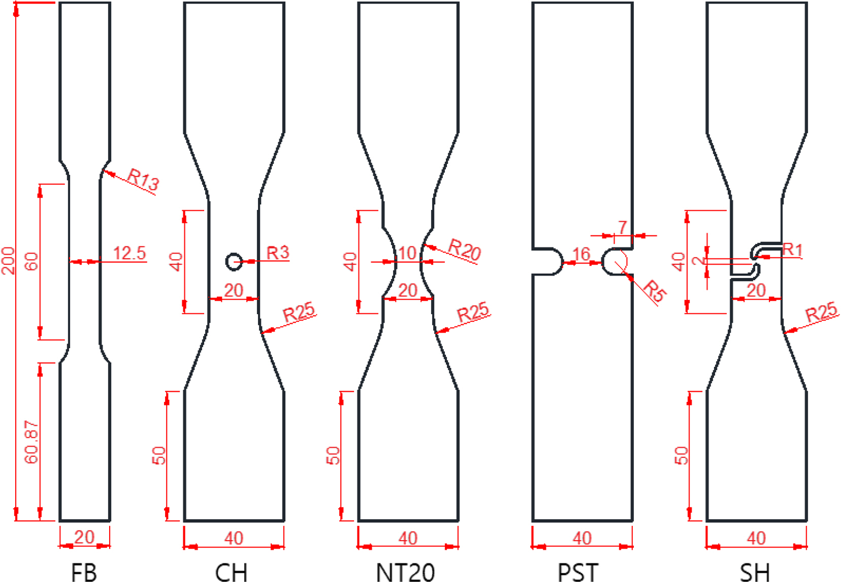
Fig. 3 shows the drawing and names of tensile specimens fabricated for the calibration of flow stress and fracture model material constants. The specimens were processed in the direction perpendicular to the steel processing direction, and the specimen thickness was 1.9 mm, which is the same as that of the base material. The dimensions of the flat smooth bars (FB) were in accordance with ASTM (2004) standards. A notched tension specimen (NT20) was used to verify the flow stress owing to its high elongation to fracture and excellent experimental reproducibility. The central hole specimen (CH) had a hole of radius of 4 mm at the center of the specimen, and it was designed to derive the stress state parameter in a pure tensile state at the fracture point. PST and pure shear (SH) specimens were designed to induce fracture states owing to PST and pure shear, respectively.
A tensile test was performed at room temperature through displacement control at a stroke speed of 0.5 mm/min using a universal material testing machine. In the experiment, the load of the lode cell and the displacement of the 50 mm extensometer were measured. The obtained load–displacement curve was used for the quantitative verification of the numerical analysis.

3.2 Numerical Analysis

3.2.1 Finite element modeling

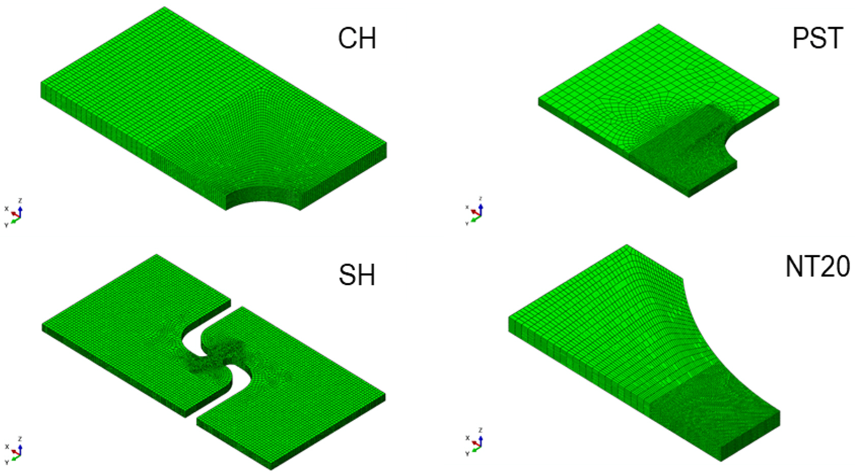
A numerical analysis of each specimen is essential to derive the loading path at the fracture point. Fig. 4 shows the finite element model. CH, PST, and NT20 modeling was performed based on an 1/8 modeling by applying symmetrical conditions in the length, width, and thickness directions of the specimen. The shear specimens were modeled based on a 1/2 modeling through symmetrical conditions with respect to the thickness direction of the specimen. Each specimen was produced up to 50 mm, to which the extensometer was attached. In addition, by increasing the element size in regions far from the predicted fracture notch of the specimen, the time cost of numerical analysis was reduced. The size of the elements was determined by a sensitivity test according to the size of the elements. Finally, 10 elements were arranged in the thickness direction of the specimen.

3.2.2 Flow stress calculation

The true strain–true stress curve obtained through the tensile testing of smooth specimens is not valid beyond the ultimate strength, at which specimen non-uniformity occurs. In the numerical analysis of a fracture accompanied by a large strain, the flow stress is extrapolated using the Swift constitutive equation. The Swift construction equation including the yield plateau where the initial yield stress is maintained comprises two parts: before and after ε̄plat where the yield plateau ends, as shown in Eq. (19).
(19)
k=f[ɛ¯p]={σ0ifɛ¯pɛ¯platA(ɛ0+ɛ¯p)nifɛ¯p>ɛ¯plat
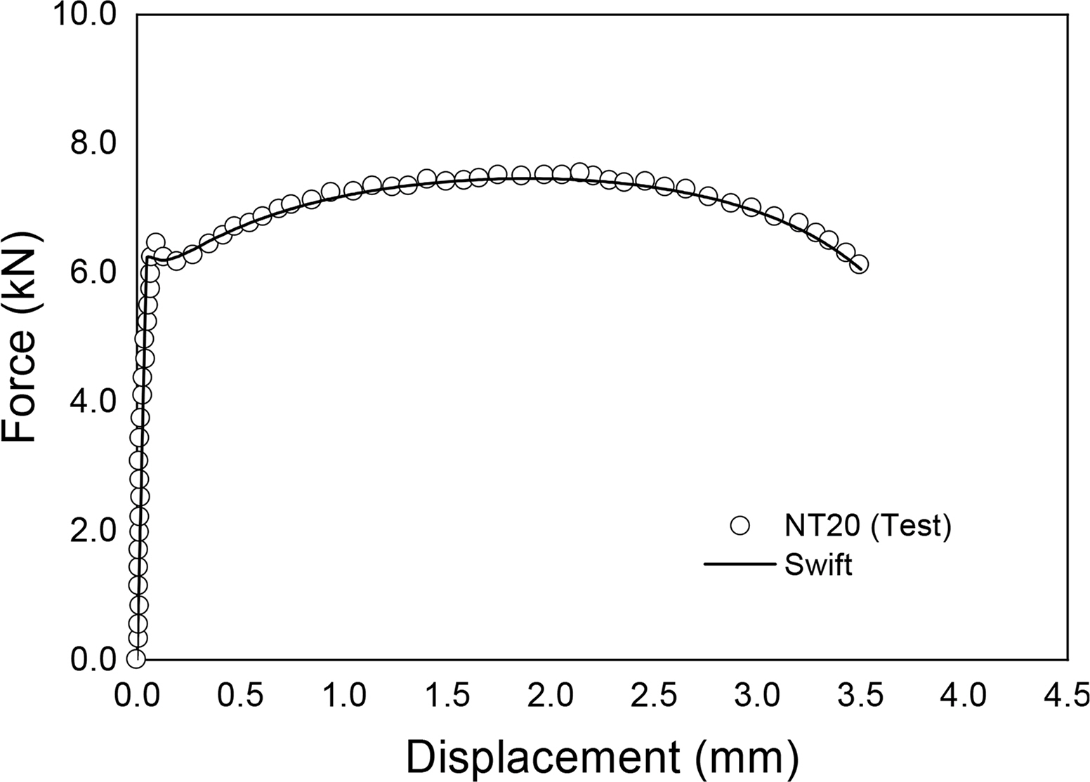
The material constants of the Swift constitutive equation, {A, ε0, n} were determined through a fit to the uniform-true-stress–uniform-true-strain curve obtained from the smoothing material experiment up to the ultimate strength. The flow stress is shown in Fig. 5, and it was used to compute the numerical analysis results and experimental results of NT20, which are shown in Fig. 6. It was confirmed from the numerical analysis results of NT20 that the flow stress, which was suggested from the numerical analysis, matched the experimental results accurately.

3.2.3 Loading path review

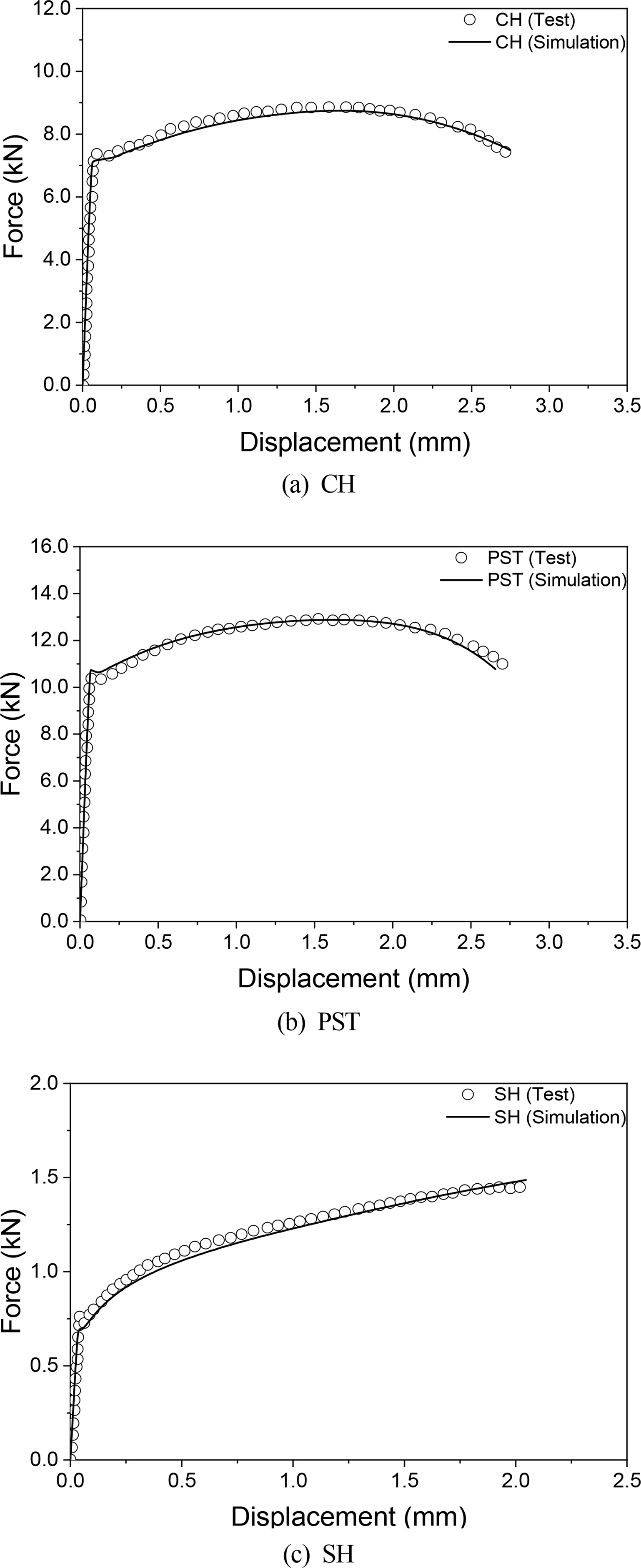
In this study, the time at which specimen fracture occurred was defined as the time at which the specimen suddenly lost its stiffness and the load rapidly decreased during the experiment. In the numerical analysis, the fracture initiation part was defined as the factor with the largest equivalent plastic strain at the time of fracture. Fig. 7 shows a load–displacement curve obtained from the experiments and numerical analysis of CH, PST, and SH until the point of failure. The numerical analysis results are consistent with the experiment results.
Fig. 8 shows the stress state parameter variability according to the equivalent plastic strain at the fracture point of each specimen. It was observed that CH exhibited a relatively small stress state variability. In the case of PST, it was confirmed that the variability of the stresstriaxiality was greater than that of the Lode angle because the initial notch radius did not maintain the shape as the specimen was subjected to a tensile force. In the case of SH, it was discovered that a tensile–shear combined load was applied in the initial pure tension as it approached the fracture point.

3.3 Determination of Fracture Model Material Constants

An optimization technique was applied to determine the material constants of the HC model. The design variables were set to the material constants of the HC model, the constraint to the range of the material constants, and the objective function to the minimum value of the error residual sum of squares (R2) (Eq. (20)). The residual sum of squares of error means the sum of squares of the ratio of the loading path data to the corresponding predicted data, ɛ¯HCpr, as shown in Eq. (21). The numerical analysis data of each specimen comprised at least 300 data points until failure occurred such that the error occurring in the entire loading path was minimized. i indicates the number of experiments conducted to calibrate the material constant. The material constants of the DSSE model were determined using Eqs. (16) and (17). Table 2 shows the material constants of the final version of the HC model as well as the design variables, constraints, residual sum of squares, and material constants of the DSSE model.
(20)
R2={|(0ɛ¯pfdɛ¯pɛHCpr¯)|-1}2
(21)
α¯=argmin{i=13{|(0ɛ¯fdɛ¯pɛ¯HCpr)|i-1}2}
Fig. 9(a) shows the HC model in a three-dimensional plane. It was observed that JIS G3131 SPHC steel was more sensitive to the volatility of the stress triaxiality than the lode angle. Fig. 9(b) shows the HC-DSSE model in the plane stress state. It was observed that the HC and DSSE models indicated the lowest strain in the PST, and that the necking condition of the DSSE was significantly lower than that of the HC model.

4. Semistatic Punching Experiment and Simulation

4.1 Experiment Summary

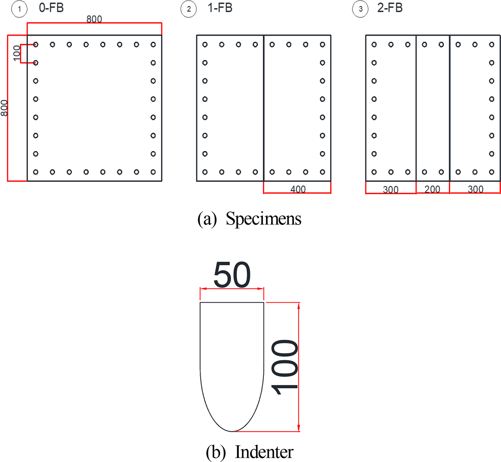
In this study, for the quantitative verification of the proposed HC–DSSE fracture model, an unstiffened and two stiffened panels punching fracture experiments of the same JIS G3131 SPHC steel and a shell-element-based fracture simulation were performed. The experimental setup is shown in Fig. 10, where the specimen was bolted to the jig to be fixed, to which a forced displacement of the indenter was applied. The indenter was manufactured in an ellipse shape of radii 50.0 and 25.0 mm in the major and minor axes, respectively (Fig. 11 (b)), and the major axis was in contact with the specimen. The drawings and names of the unstiffened and stiffened panels are shown in Fig. 11 (a). The unstiffened panel (0-FB) measured 800 mm × 800 mm × 1.9 mm, whereas the reinforcement measured 25.0 mm in height and 1.9 mm in thickness. For the stiffened panels, the stiffener was welded to the unstiffened panel, and depending on the number of reinforcing materials used, it was categorized into 1-FB for one reinforcing material, and 2-FB for two reinforcing materials. The thickness centerline of the reinforcing material of 1-FB coincided with that of the stiffened panels. Therefore, the indenter penetrated the stiffener. The centerline of the 2-FB reinforcing material was 100 mm off the centerline of the specimen, and an indenter penetrated between the stiffeners. It was single-pass welded using a TIG (tungsten inert-gas arc welding) arc welding machine. The welding speed was 5.0 mm/min, the rated output current was 50 A, and the load voltage is 70 V. The effective width excluding the specimen support was 600.0 mm × 600.0 mm. To evenly distribute the force to the fixed part of the specimen, a cover was separately manufactured. The forced displacement speed of the indenter was 10 mm/min. The stroke displacement and load were measured from the experiment.

4.2 User Subroutine Development

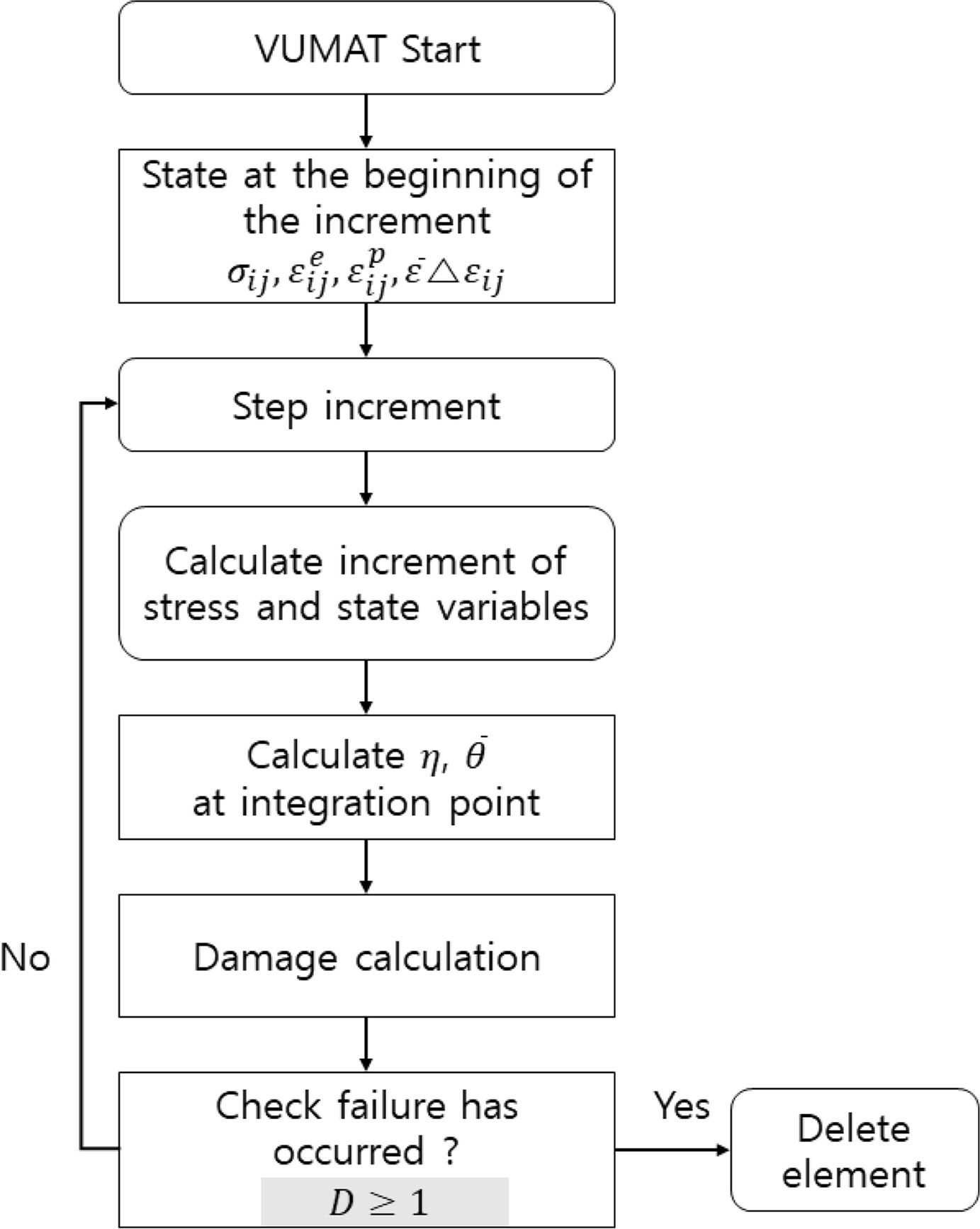
Through the development of the user subroutine of Abaqus/Explicit, a commercial finite element analysis program, the HC–DSSE model was applied as a fracture criterion. Fig. 12 shows the general algorithm of the material user subroutine, VUMAT. A single shell element has a section point in the component thickness direction. In this study, a four-node reduced integration (S4R) shell element with five integral thickness points, which is provided by Abaqus/Explicit, was used in the modeling. When one of the five-section points reached DHC = 1.0 or all five integration points reach DDSSE = 1.0, the integration point loses its stiffness and deleted. An element is deleted if all integration points lose their stiffnesses.

4.3 Numerical Analysis

4.3.1 Numerical analysis of unstiffened panel

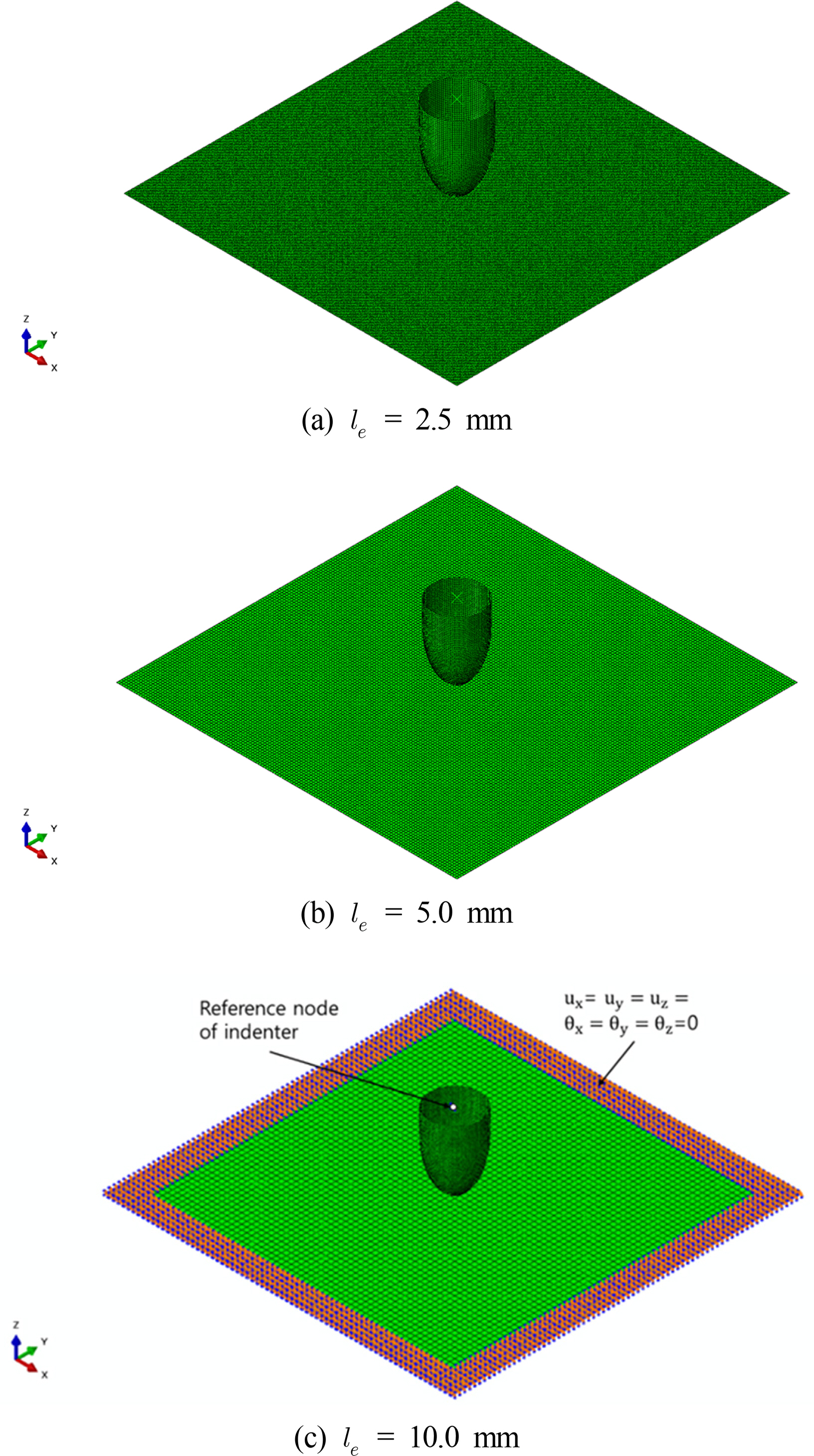
The finite element model of the unstiffened panel specimen was generated using an S4R shell element. The indenter was modeled with a four-node rigid element. To verify the sensitivity of the element size, the element size of the unstiffened panel was modeled such that the ratio of the specimen thickness of 1.9 mm to the element length le was approximately 5.0 (le = 10.0 mm), 2.5 (le = 5.0 mm), and 1.25 (le = 2.5 mm). The modeling according to the boundary conditions and element size of the numerical analysis is shown in Fig. 13. The shell element was created for the entire width of the specimen (800 mm × 800 mm), and the six degrees of freedom of the specimen fixture, except for the effective width (600 mm × 600 mm), was fixed. The load was implemented by applying a forced displacement to the reference node of the rigid element (indenter). The speed of the indenter was 10 mm per minute, which was slow; hence, the analysis time was long. To address this problem, mass scaling and energy balance methods can be used. Because mass scaling can significantly induce the effect ofinertia force at high-speed deformation during fracture, the analysis time was accelerated using energy balance. In other words, the simulation time was reduced by increasing the speed of the indenter such that the ratio of the kinetic energy to the total energy was maintained within 1.0%. After the speed was determined, the friction coefficient was determined such that the error rate of the load–displacement curve slope was the smallest in the experiment through repeated numerical analyses. According to numerical analysis, the friction coefficient was assumed to be 0.23.
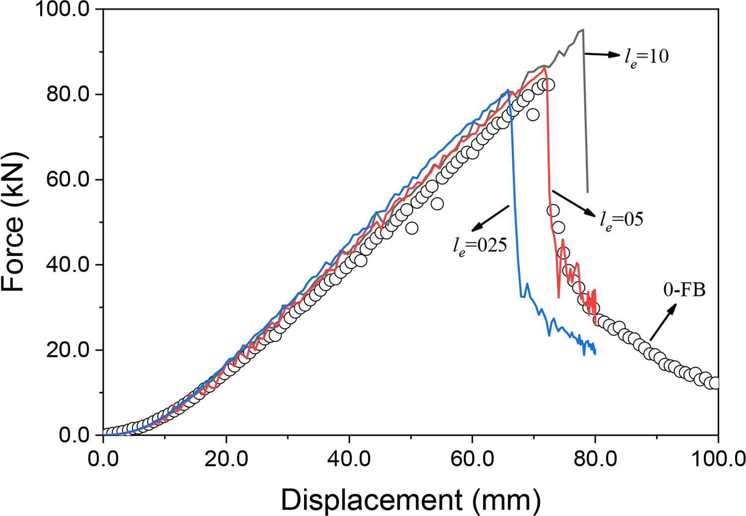
Fig. 14 shows the load–stroke displacement curves from the unstiffened panel experiment and the numerical analysis. Based on the numerical analysis result, it was discovered that the fracture displacement differed according to the element size. In this study, the effect of the shell element size on the fracture strain was not considered, and because the shell element size that yielded the most accurate simulation result was 5.0 mm (le/t = 2.5), 5.0 mm was selected as the final element size. Fig. 15 shows the stress triaxiality according to the equivalent plastic strain increment of the indenter top surface and the bottom surface selection point of the fracture initiation point.
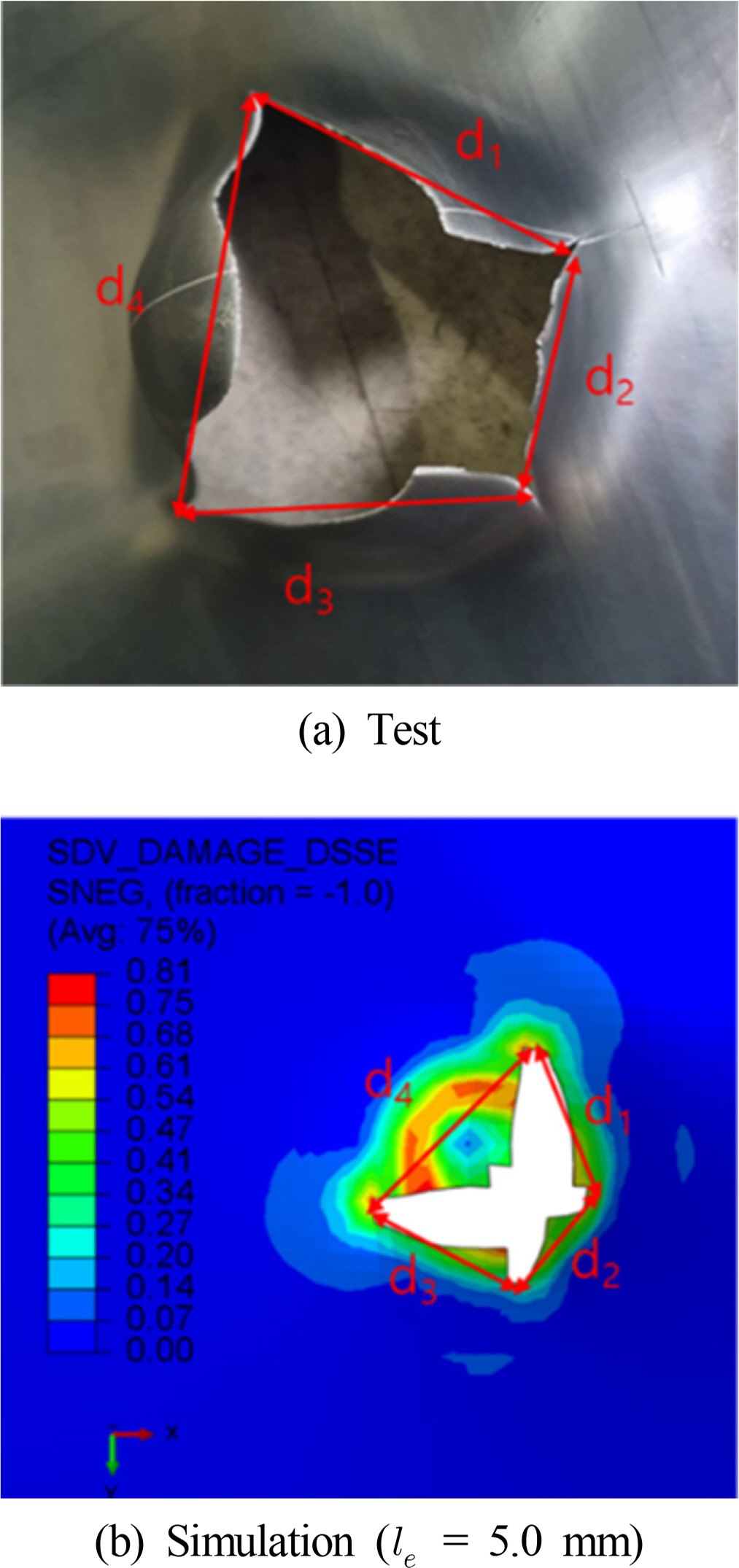
It was discovered that the stress states of the top (the indenter contact surface) and bottom surfaces of the specimen at the fracture point were highly strained under nearly equi-biaxial tension. Fig. 16 and Table 3 show the fracture extents of the final displacement results in the experiment and numerical analysis. From these results, it was discovered that the final fracture shape of the simulation analysis matched well with that of the experiment.

4.3.2 Numerical analysis of reinforcing plates

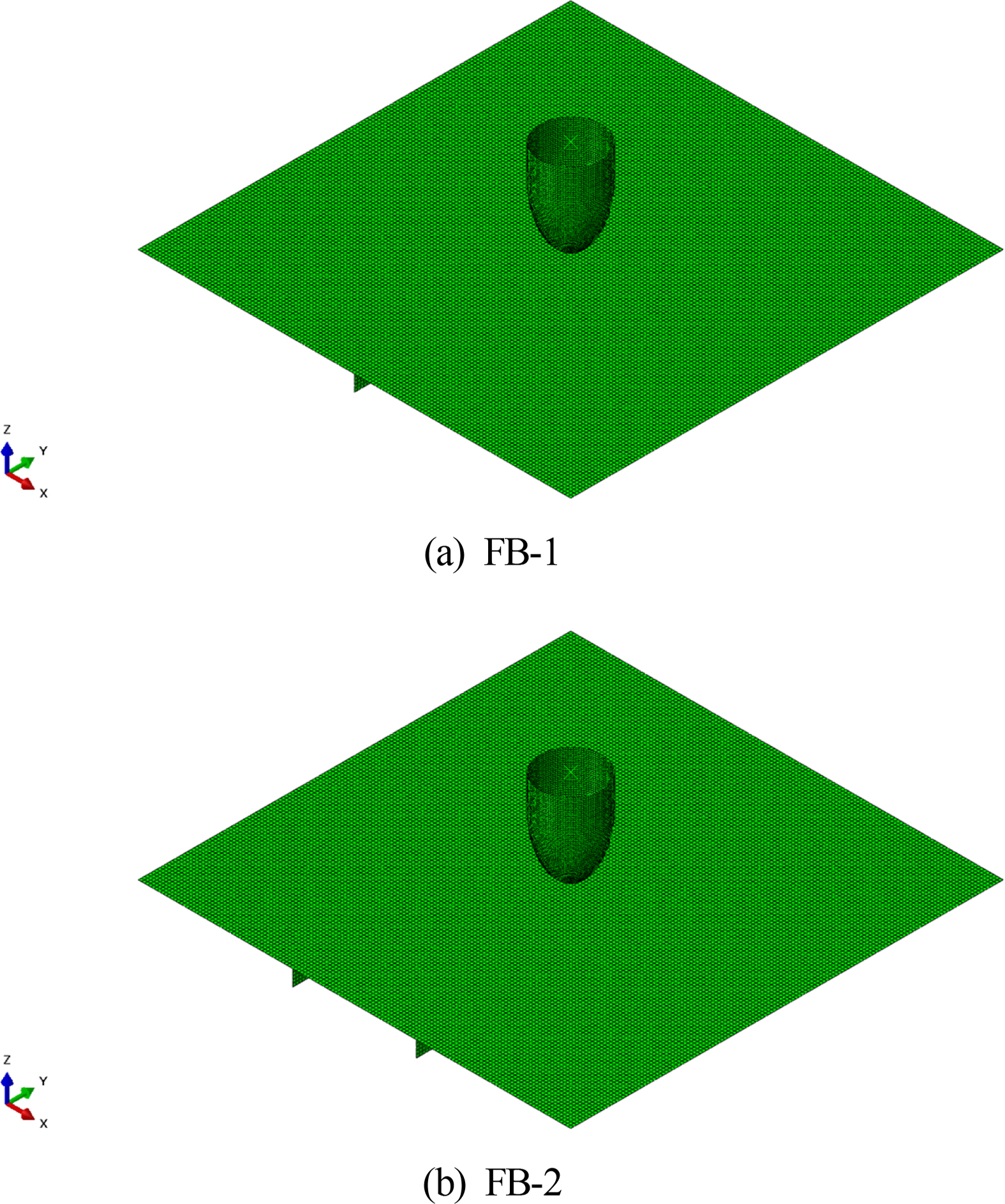
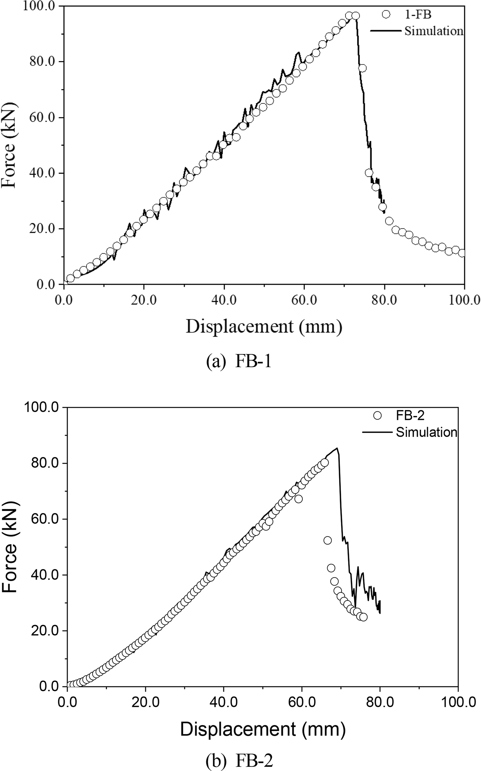
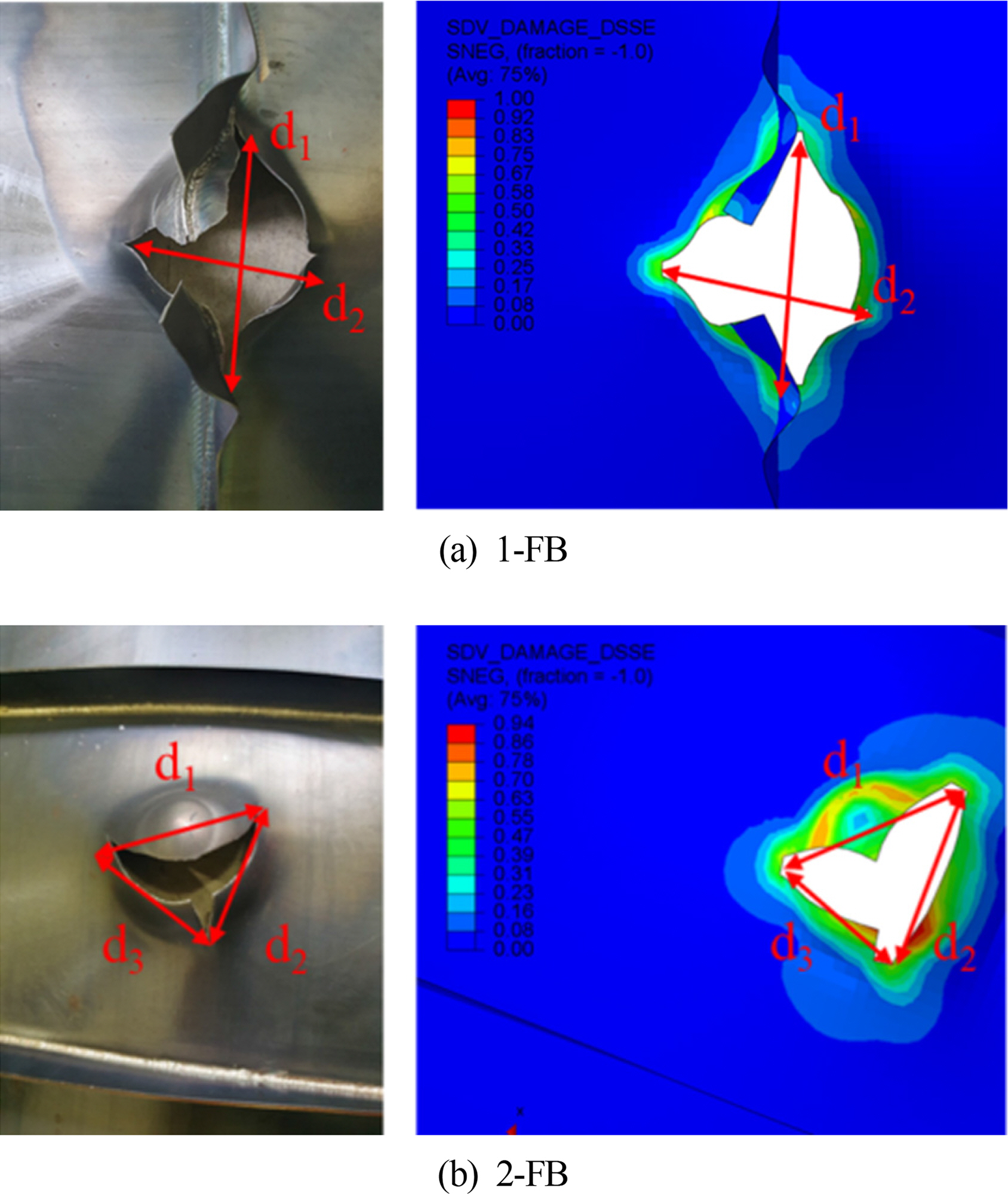
The element size of the stiffened panels in the modeling was le = 5.0, which was determined through the element size convergence test of the unstiffened panel. The FB-1 and FB-2 numerical analysis models are shown in Fig. 17. The boundary conditions and analysis conditions were the same as those for the unstiffened panel. Fig. 18 shows the numerical analysis results. It was observed that the fracture displacement and maximum load in the numerical analysis of 1-FB were similar to the experimental values. The error rates of the fracture initiation load and the fracture initiation displacement in the 2-FB numerical analysis were 6% and 8.4%, respectively. Fig. 19 shows the fractures of the specimens obtained from the experiments and numerical analyses of 1-FB and 2-FB. Table 4 shows a comparison of the fracture ranges from the experiments and numerical analysis, in which a relatively small error rate was observed.

5. Conclusion

Tensile specimens were fabricated using smooth bars for general structural steels and tested, in which nonlinear numerical analysis and extrapolation were used to obtain the flow stress values up to the large strain section. To obtain the material constants for the HC fracture model and DSSE fracture model, various notched specimens were fabricated and tested on the same steel, and the flow stress results were applied to the nonlinear numerical analysis model to confirm the quantitative numerical analysis results. An optimization method was applied to the numerical analysis results of these material constant acquisition specimens to acquire the material constants of the HC and DSSE models.
A user subroutine was developed to apply the HC–DSSE fracture model as a fracture condition to a commercial finite element analysis program. Furthermore, to conduct a quantitative verification of the fracture model, a punching experiment of a unstiffened/stiffened panels and a fracture simulation based on a shell element were performed. The element size of the numerical model of the stiffened panels was determined by the sensitivity test of the shell element size for the numerical analysis of the unstiffened panel. Local necking occurred in the local area on the materials and structures, whereas dense elements simulated the exact necking point in the numerical analysis. Although the DSSE model considered necking and ductile fracture displacement to be closely related, it was difficult to ascertain exactly when the actual fracture occurred after the necking. Therefore, considering the exact necking point as a fracture using a dense element can underestimate the fracture displacement. This effect can be corrected by sufficiently enlarging the element size. It was confirmed in this study that the numerical analysis result predicted the fracture behavior of the structure the most accurately when the element size was approximately 2.5 times the thickness of the structure. In the future, it is necessary to solve the component sensitivity issue of the fracture model by conducting studies, such as the correction of fracture strain according to the element size. Furthermore, accidents such as the collision and stranding of the ship’s offshore structures typically cause dynamic loads on the structures. To apply the ductile material fracture model to these problems, studies on the effect of strain rate on ductile fracture should be conducted in the future.

Notes

Author ORCIDs and Contributions
Author name ORCID Contributions
Park, Sung-Ju 0000-0002-7129-8567 ①②③④
Choung, Joonmo 0000-0003-1407-9031
① Conceived of the presented idea or developed the theory
② Carried out the experiment or collected the data
③ Performed the analytic calculations or numerical simulations
④ Wrote the manuscript
⑤ Supervised the findings of this study

Acknowledgements

This work was supported by Korea Environment Industry & Technology Institute (KEITI) through Industrial Fac ilities & Infrastructure Research Program, funded by Korea Ministry of Environment(MOE)(146836). This research weas funded and conducted under 「the Competency Development Program for Industry Specialists」 of the Korean Ministry of Trade, Industry and Energy (MOTIE), operated by Korean Institute for Advancement of Technology (KIAT). (No. N0001287, HRD program for Korea-UK Global Engineer Education Program for Offshore Plant)

Fig. 1
Stress states on the plane of stress triaxiality and Lode angle parameter (Cerik et al., 2019a)
joet-34-3-155f1.jpg
Fig. 2
A schematic curves of ductile fracture and necking limit
joet-34-3-155f2.jpg
Fig. 3
Design of the specimens (unit: mm)
joet-34-3-155f3.jpg
Fig. 4
Finite element models of the specimens
joet-34-3-155f4.jpg
Fig. 5
Flow stress of JIS G3131 SPHC
joet-34-3-155f5.jpg
Fig. 6
Comparison of experimental and numerically predicted force-displacement curve of NT20
joet-34-3-155f6.jpg
Fig. 7
Comparison of force-displacement between test and simulation
joet-34-3-155f7.jpg
Fig. 8
Evolution of the equivalent plastic strain against stress state parameters
joet-34-3-155f8.jpg
Fig. 9
Fracture locus of JIS G3131 SPHC grade steel
joet-34-3-155f9.jpg
Fig. 10
Schematic and photo of a punch test
joet-34-3-155f10.jpg
Fig. 11
Drawing of the test specimens and indenter (unit: mm)
joet-34-3-155f11.jpg
Fig. 12
Material user subroutine algorithm
joet-34-3-155f12.jpg
Fig. 13
Finite element models of un-stiffened panel
joet-34-3-155f13.jpg
Fig. 14
Comparison of displacement-force curve between un-stiffened panel test and simulation
joet-34-3-155f14.jpg
Fig. 15
Evolution of stress triaxiality in the fracture initiation element (mesh size: 5.0 mm)
joet-34-3-155f15.jpg
Fig. 16
Comparison of fracture propagation between un-stiffened panel tests and simulations
joet-34-3-155f16.jpg
Fig. 17
Finite element models of stiffened panel
joet-34-3-155f17.jpg
Fig. 18
Comparison of force-displacement curves obtained tests and simulation
joet-34-3-155f18.jpg
Fig. 19
Comparison of fracture propagation between stiffened panel test and simulations
joet-34-3-155f19.jpg
Table 1
Chemical composition of JIS G3131 SPHC steel
Material C Si Mn P S
JIS G3131 SPHC 0.0509 0.02 0.24 0.014 0.0062
Table 2
Calibrated HC-DSSE model parameters
Constraint HC model parameters R2 DSSE parameter
a b c d
1.0≤a≤2.0 1.5979 1.3599 0.0012 0.0007 1.7027
0.1≤ b ≤2.0
0.0001≤c≤0.2
Table 3
Comparison of the experimentally measured and numerically predicted rupture size for un-stiffened panel test
Case d1 (mm) d2 (mm) d3 (mm) d4 (mm)
0-FB (Test) 7.3 5.1 7.1 8.7
0-FB (Simulation) 7.32 5.2 6.63 8.04
Error 0.27 1.96 6.62 7.59
Table 4
Comparison of the experimentally measured and numerically predicted rupture size for stiffened panel test
Case d1 (mm) d2 (mm) d3 (mm)
1-FB (Test) 12.0 9.9 -
1-FB (Simulation) 11.70 9.73 -
Error 2.50 1.72 -

2-FB (Test) 8.0 8.0 7.0
2-FB (Simulation) 7.9 7.3 6.7
Erorr 1.25 8.75 4.29

References

Algarni, M., Choi, Y., & Bai, Y. (2017). A Unified Material Model for Multiaxial Ductile Fracture and Extremely Low Cycle Fatigue of Inconel 718. International Journal of Fatigue, 96, 162-177. https://doi.org/10.1016/j.ijfatigue.2016.11.033
crossref
American Society for Testing and Materials (ASME). (2004). Standard Test Methods of Tension Testing of Metallic Materials (ASTM E8), American Society for Testing and Materials.

Bai, Y., & Wierzbicki, T. (2008). A New Model of Metal Plasticity and Fracture with Pressure and Lode Dependence. International Journal of Plasticity, 24(6), 1071-1096. https://doi.org/10.1016/j.ijplas.2007.09.004
crossref
Bai, Y., & Wierzbicki, T. (2010). Application of Extended Mohr- Coulomb Citerion to Ductile Fracture. International Journal of Fracture, 161(1), 1-20. https://doi.org/10.1007/s10704-009-9422-8
crossref pdf
Cerik, BC., & Choung, J. (2020). On the prediction of ductile fracture in ship structures with shell elements at low temperatures. Thin-Walled Structures, 151, 106721. https://doi.org/10.1016/j.tws.2020.106721
crossref
Cerik, BC., Lee, K., Park, SJ., & Choung, J. (2019a). Simulation of Ship Collision and Grounding Damage Using Hosford-Coulomb Fracture Model for Shell Elements. Ocean Engineering, 173, 415-432. https://doi.org/10.1016/j.oceaneng.2019.01.004
crossref
Cerik, BC., Ringsberg, JW., & Choung, J. (2019b). Revisiting MARSTRUCT Benchmark Study on Side-shell Collision with a Combined Localized Necking and Stress-state Dependent Ductile Fracture Model. Ocean Engineering, 187, 106173. https://doi.org/10.1016/j.oceaneng.2019.106173
crossref
Cerik, BC., Park, B., Park, SJ., & Choung, J. (2019c). Modeling, Testing and Calibration of Ductile Crack Formation in Grade DH36 Ship Plates. Marine Structures, 66, 27-43. https://doi.org/10.1016/j.marstruc.2019.03.003
crossref
Choung, J., & Cho, SR. (2008). Study on True Stress Correction from Tensile Tests. Journal of Mechanical Science and Technology, 22, 1039-1051. https://doi.org/10.1007/s12206-008-0302-3
crossref pdf
Choung, J., Park, SJ., & Kim, Y. (2015a). Development of Three Dimensional Fracture Strain Surface in Average Stress Triaxiaility and Average Normalized Lode Parameter Domain for Arctic High Tensile Steel: Part I Theoretical Background and Experimental Studies. Journal of Ocean Engineering and Technology, 29(6), 445-453. https://doi.org/10.5574/KSOE.2015.29.6.445
crossref pdf
Choung, J., Park, SJ., & Kim, Y. (2015b). Development of Three-Dimensional Fracture Strain Surface in Average Stress Triaxiaility and Average Normalized Lode Parameter Domain for Arctic High Tensile Steel: Part II Formulation of Fracture Strain Surface. Journal of Ocean Engineering and Technology, 29(6), 454-462. https://doi.org/10.5574/KSOE.2015.29.6.454
crossref pdf
Cho, SR., Park, JY., Song, SU., & Park, SH. (2018). Scale Effects on the Structural Behavior of Steel Unstiffened Plates Subjected to Lateral Collisions. Journal of the Society of Naval Architects of Korea, 55(2), 178-186. https://doi.org/10.3744/SNAK.2018.55.2.178
crossref
Ehlers, S., Broekhuijsen, J., Alsos, HS., Biehl, F., & Tabri, K. (2008). Simulating the collision response of ship side structures: A failure criteria benchmark study. International Shipbuilding Progress, 55(1), 127-144. https://doi.org/10.3233/ISP-2008-0042
crossref
Johnson, GR., & Cook, WH. (1985). Fracture Characteristics of Three Metals Subjected to Various Strain, Strain Rates Temperatures and Pressures. Engineering Fracture Mechanics, 21(1), 31-48. https://doi.org/10.1016/0013-7944(85)90052-9
crossref
Mohr, D., & Marcadet, S. (2015). Micromechanically-motivated Phenomenological Hosford-coulomb Model for Predicting Ductile Fracture Initiation at Low Stress Triaxialites. International Journal of Solids and Structures, 67-68 40-55. https://doi.org/10.1016/j.ijsolstr.2015.02.024
crossref
Min, DK., & Cho, SR. (2012). On the Fracture of Polar Class Vessel Structures Subjected to Lateral Impact Loads. Journal of the Society Naval Architects of Korea, 49(4), 281-286. https://doi.org/10.3744/SNAK.2012.49.4.281
crossref pdf
Nho, IS., Park, MJ., & Cho, YS. (2018). Preliminary Structural Design of Blast Hardened Bulkhead (The 2nd Report : Scantling Formula for Curtain Plate Type Blast Hardened Bulkhead). Journal of the Society Naval Architects of Korea, 55(5), 379-384. https://doi.org/10.3744/SNAK.2018.55.5.379
crossref
Pack, K., & Mohr, D. (2017). Combined Necking & Fracture Model to Predict Ductile Failure with Shell Finite Elements. Engineering Fracture Mechanics, 182, 32-51. https://doi.org/10.1016/j.engfracmech.2017.06.025
crossref
Park, SJ., Lee, K., & Choung, J. (2016). Punching Fracture Simulations of Circular Unstiffened Steel Plates Using Three-dimensional Fracture Surface. Journal of Ocean Engineering and Technology, 30(6), 474-483. https://doi.org/10.5574/KSOE.2016.30.6.474
crossref pdf
Park, SJ., Park, B., & Choung, J. (2017). Ductile fracture predictions of High Strength Steel (EH36) Using Linear and Non-Linear Damage Evolution Models. Journal of Ocean Engineering and Technology, 31(4), 288-298. https://doi.org/10.26748/KSOE.2017.08.31.4.288
crossref pdf
Park, SJ., Lee, K., Cerik, BC., Kim, Y., & Choung, J. (2019a). Ductile Fracture of a Marine Structural Steel Based on HC-DSSE Combined Fracture Strain Formulation. Journal of the Society of Naval Architects of Korea, 56(1), 82-93. https://doi.org/10.3744/SNAK.2019.56.1.082
crossref
Park, SJ., Lee, K., Cerik, BC., & Choung, J. (2019b). Ductile Fracture Prediction of EH36 Grade Steel Based on Hosford-Coulomb Model. Ships and Offshore Structures, 14, 68-78. https://doi.org/10.1080/17445302.2019.1565300
crossref
Park, SJ., Cerik, BC., & Choung, J. (2020). Comparative Study on Ductile Fracture Prediction of High-tensile Strength Marine Structural Steels. Ships and Offshore Structures. https://doi.org/10.1080/17445302.2020.1743552
crossref
Ringsberg, JW., Amdahl, J., Chen, BQ., Cho, SR., Ehlers, S., Hu, Z., & Zhang, S. (2018). MARSTRUCT Benchmark Study on Nonlinear FE Simulation of an Experiment of an Indenter Impact with a Ship Side-shell Structure. Marine Structures, 59, 142-157. https://doi.org/10.1016/j.marstruc.2018.01.010
crossref
Roth, CC., & Mohr, D. (2016). Ductile Fracture Experiments with Locally Proportional Loading Histories. International Journal of Plasticity, 79, 328-354. https://doi.org/10.1016/j.ijplas.2015.08.004
crossref
Xue, L. (2007). Damage Accumulation and Fracture Iinitiation in Uncracked Ductile Solids Subject to Triaxial Loading. International Journal of Solids and Structures, 44(16), 5163-5181. https://doi.org/10.1016/j.ijsolstr.2006.12.026
crossref


ABOUT
BROWSE ARTICLES
ARTICLE CATEGORY

Browse all articles >

PUBLICATION ETHICS
FOR CONTRIBUTORS
Editorial Office
President Office BD Rm. 1302, 13 Jungang-daero 180beon-gil, Dong-gu, Busan 48821, Republic of Korea
Tel: +82-51-759-0656    Fax: +82-51-759-0656    E-mail: ksoehj@ksoe.or.kr                

Copyright © 2024 by The Korean Society of Ocean Engineers.

Developed in M2PI

Close layer
prev next