Study for Operation Method of Underwater Cable and Pipeline Burying ROV Trencher using Barge and Its Application in Real Construction
Article information

Abstract
We developed a heavy-duty work class ROV trencher named URI-T (Underwater robot it’s trencher) that can conduct burial and maintenance tasks for underwater cables and small diameter pipelines. It requires various supporting systems, including a dynamic positioning (DP) vessel, launch and recovery system (LARS), A-frame, and winch in order to perform burial tasks because of its dimensions (6.5 m × 5.0 m × 4.5 m, 20 t) and the tough working environment. However, operating a DP vessel has disadvantages as it is expensive to rent and operate and it is difficult to adjust the working schedule for some domestic coast construction cases. In this paper, we propose a method using a barge instead of a DP vessel to avoid the above disadvantages. Although burying the cable and pipeline using a barge has lower working efficiency than a DP vessel, it can save construction expenses and does not require a large crew. The proposed method was applied over two months at the construction of the water supply in Yokji-do, and the results were verified.
1. Introduction
In general, subsea cables and pipelines are buried for the purpose of supplying power and communication between land and islands (subsea cables), transporting fossil fuels (pipelines), and connecting waterworks (pipelines). Since these cables and pipelines are exposed to man-made hazards (tools such as anchors, trawl doors, etc.) and natural hazards (earthquakes, typhoons, etc.) (Jones and Hirai, 2001; Yoo and Shin, 2010), the burial is performed using various protection methods for economical feasibility and stability (Ahn and Kim, 2009). This research institute developed an underwater heavy-duty Remotely Operated Vehicle (ROV) trencher (Underwater Robot. It’s Trencher, URI-T) to conduct the post-lay inspection and burial (PLIB) of pre-laid cables and pipelines beneath the seabed using a water jetting system. URI-T was one part of a project to develop underwater robots for the construction of marine structures and infrastructure for performance verification from 2013 to 2019 (Jang, 2014) (Fig. 1). Subsequently, from 2019 to the present, the performance of URI-T, which was developed to promote the use of marine equipment research results, has been enhanced, and efforts are being made to secure commercial results by introducing the ROV trenchers on-site. As described above, the URI-T is an ROV trencher that buries and maintains cables and pipelines using water jetting and various work tools at depths of up to 2,500 m; it is 6.6 m (L) × 4.5 m (W) × 3.5 m (H) and weighs approximately 21 tons (Kang et al., 2019; Cho, et al., 2019a).
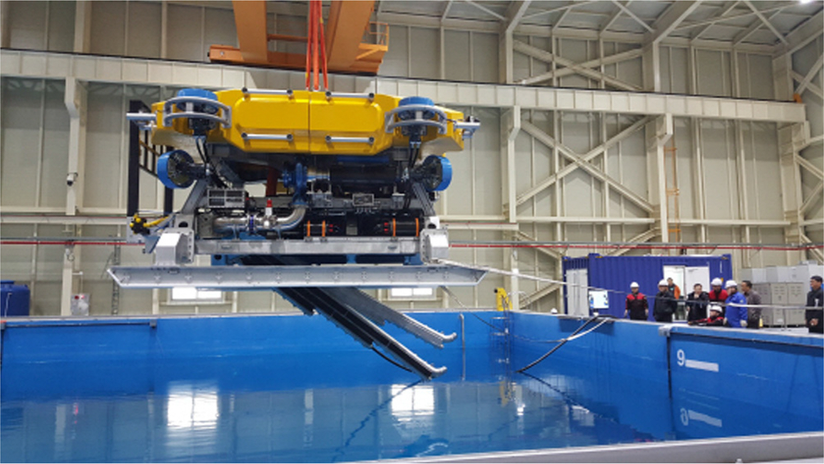
ROV Trencher, URI-T
At an actual burial work site, it is necessary to have a dynamic positioning (DP) vessel equipped with a launch and recovery system (LARS), including a winch and an A-Frame to launch and recover the ROV trencher and move the ship according to the movement of the ROV trencher. The A-Frame is a device used to stably move the ROV trencher from the deck to the surface of the water; it is used with a winch that winds and unwinds an umbilical cable used for the power supply and communication connection of the ROV trencher (Fig. 2). When the URI-T is operated using a DP vessel, the work efficiency can be maximized by enabling continuous operation for 24 hours, and the work stability can be improved by using a dedicated launch and recovery device. Nevertheless, a large amount of manpower is required for the operation of ships and ROV trenchers. Moreover, the rental and operation cost of ships is high, and it is difficult to coordinate rental schedules when using foreign ships. It is not easy to use both domestic and foreign DP vessels at some domestic sites that require burial tasks (e.g., for the construction work on the water supply in Yokji-do) because the work zone is small (within 10 km) and construction must be conducted with a fixed schedule and cost.

A LARS with a winch and A-Frame
In this paper, we introduce the method of operating the ROV trencher using a barge. The method can be applied to several burial work sites in Korea where it is difficult to use DP vessels. Each function of the DP vessel and its accompanying LARS device are replaced by using an anchor winch, a crane, and the newly designed cable handling system of the barge. Some of the existing operation scenarios are modified accordingly to the method. The proposed method was successfully applied to the Yokji-do waterworks construction that was conducted from November 2019 to January 2020. Using barges for the burial of subsea cables and pipelines has lower operational efficiency and operational stability than using DP vessels. However, since the rental cost of barges is comparatively low and manpower required for their operation is smaller, using barges can significantly reduce construction cost and facilitate schedule coordination in short work zones on the domestic coast. In Chapters 2 to 4, the overall system of the URI-T, its proposed method of operation, and its application to the Yokji-do waterworks construction are described, respectively. Conclusions and future plans are discussed in Chapter 5.
2. URI-T System Overview
The detailed performance and specifications of the URI-T are described in detail in Tables 1 and 2 below.
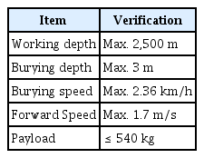
URI-T performance

URI-T’s specifications (Kang et al., 2019)
The URI-T is divided into a hydraulic system, a water jet system, an onboard remote control and power supply system, a hydraulic-based cable work tool, and a manipulator system. Details for each system follow.
Hydraulic system: A 250 kW hydraulic powered unit (HPU) is used to control the position and location of the ROV trencher and to drive the burial and maintenance tools. The HPU supplies the flow to 4 valve packs (2 for driving a thruster and 2 for driving a work tool), and each valve pack controls the flow rate of 8 thrusters (4 horizontal and 4 vertical thrusters), 2 manifolds (with 5 and 7 axes), 2 work tools (cutters and grippers), and 6 hydraulic cylinders (2 TSS handlers and 4 motion bases).
Water jet system: The water jet system is for spraying seawater on the seabed for a burial task. It sprays seawater by using 2 water pumps (1 port jetting arm and 1 starboard jetting arm) capable of supplying 986 m3 of water per hour and 2 jetting arms (1 port and 1 starboard) that spray water. In addition, a motion base is used to control the left/right and up/down position of the jetting arms; it can be adjusted from 0.2 m to 0.7 m in the left/right direction and by up to 3 m in up/down direction (Li et al., 2014).
Onboard remote control and power supply system: The onboard remote control system is implemented in a specially manufactured container and consists of a monitor wall, 2 control console chairs, a touch screen, and a power and communication distribution panel. It monitors the state of the URI-T and the power supply system and controls the functions and state necessary for the given task. The power supply system is implemented with two specially manufactured containers; it stably supplies the internal driving power of the URI-T and HPU and the power for the 2 water pumps.
Hydraulic-based cable work tools and manipulators: Work tools such as grippers, cutters, and manipulators are used for the maintenance of subsea cables and pipelines. The gripper and cutter are operated by the manipulator. The gripper can grip a cable with a diameter of 17 ∼ 110 mm with a force of 25 tons, and the cutter can cut a cable with a diameter of up to 110 mm using pressure of up to 69 mPa (Cho et al., 2019b).
3. Operation of the ROV Trencher using a Barge
3.1 ROV Trencher Operation Scenario using a DP Vessel
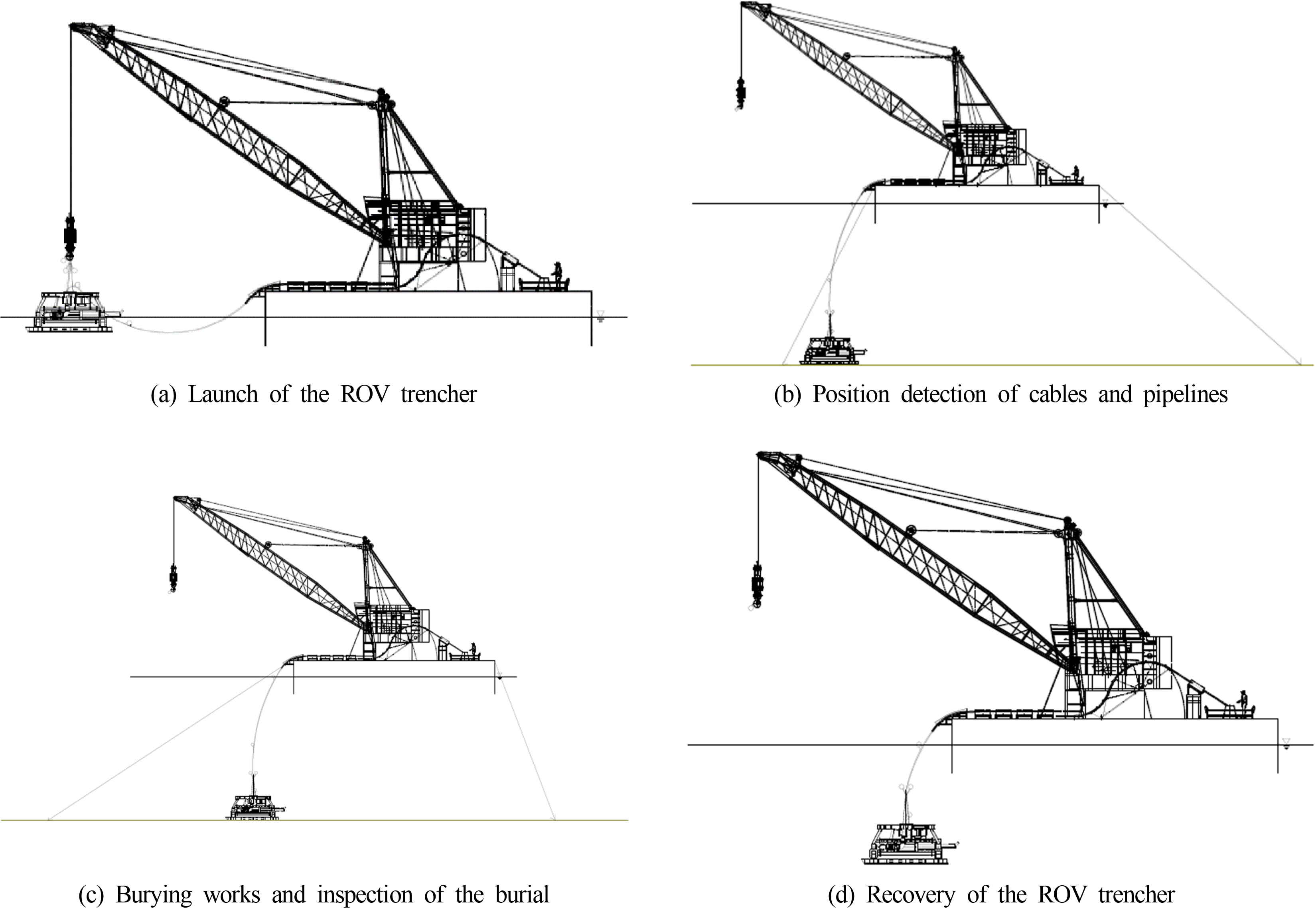
For burial tasks completed with an ROV trencher, it is typical to use a DP vessel equipped with a LARS device including a winch and A-Frame for the launch, recovery, and stability of the ROV trencher, as mentioned above. The actual operation scenario can be divided into 4 stages as shown in Fig. 3. The details are as follows.
ROV trencher launch: For a LARS device connected to the ROV trencher as shown in Fig. 2, the umbilical cable is connected to the ROV trencher through the an A-Frame, and the depth of the ROV trencher is controlled by adjusting the length of the umbilical cable with the corresponding winch controller. As shown in Fig. 3, the A-Frame is used for surface deployment from the DP ship deck. A winch is then used to position the ROV trencher on the seabed. After the ROV lands at a given depth, the position of the ROV trencher is monitored by the onboard remote control system using the Ultra-short baseline (USBL)1), and Quincy system2).
Position detection of pre-laid cables and pipelines using the cable and pipeline detection system (TSS350 and TSS440): After landing on the seabed, the ROV trencher deploys and moves the TSS handler and detects the location of cables and pipelines laid on the seabed. After the cables and pipelines have been located, the ROV trencher is placed over them. Meanwhile, the DP vessel follows the movement of the ROV trencher, keeping the umbilical cable as straight as possible. Otherwise, the ROV trencher could be inadvertently lifted by the umbilical cable and burial depth could not be guaranteed. Moreover, the umbilical cable could be damaged, causing damage or in the worst case, loss of the ROV trencher.
Cable and pipeline burial and post-lay survey: The ROV trencher located above the cables and pipelines tracks the location information of the TSS. It uses the waterjet system to perform the burial task and then uses the TSS350 and TSS440 to perform a post-lay survey after completion. Simultaneously, the DP vessel follows the movement line of the ROV trencher, keeping the umbilical cable as straight as possible.
ROV trencher recovery: The ROV trencher is recovered by steps in the reverse order of the launch. After the winch pulls the ROV trencher to the end of the A-Frame, the A-Frame is folded onto the deck of the ship. The length of the umbilical cable is then adjusted with a winch, recovering and tying it onto the deck. In the field, the work must be carried out according to the above scenario, otherwise the efficiency and accuracy of the work can be degraded, and the stability of the ROV trencher will not be guaranteed.

Operating scenario of the ROV trencher using a DP vessel
3.2 Improving the Operation of the ROV Trencher using a Barge
As mentioned above, for some burial work on the domestic coast, it is not only extremely difficult to find a DP ship in which an A-Frame or winch can be installed within the specified time limit, but the cost of construction may also be economically infeasible. A barge can therefore be a good alternative to a DP ship. When using a barge, the operational efficiency and stability are lower, but the cost of renting and operating the ship is also lower. A barge can be operated with a smaller workforce, which can provide a significant advantage at some burial sites along the domestic coast. In order to operate the ROV trencher using a barge, the following two problems must be solved: (1) When the ROV trencher moves on the seabed, as in the second and third steps of the scenario above, the barge must move with the ROV trencher (DP function). (2) A LARS device cannot be installed on a barge due to its size and weight, thus an operating system that can replace it is required. The following method is proposed to solve these problems.
It is possible to move a barge using a tugboat. This is, however, not suitable for use with an ROV trencher since the position of the barge is difficult to control and the speed is slow. We therefore propose using four or more anchors and anchor winches to fix the barge at sea, as shown in Fig. 4. The first and second anchors are used to fix the position of the barge, while the third and fourth anchors are installed at the initial working position using a tugboat. The first anchor is then retrieved and installed at the final working position using a tugboat. After the second anchor has been retrieved, it is also installed at the final working position. In this way, when the first and second anchor winches and the third and fourth anchor winches are synchronously pulled in and let out, the barge can be moved according to the movement of the ROV trencher (Fig. 5). The performance of the barge movement depends on the length of the anchor lines of the barge and the power of the anchor winches. With a single anchoring operation, the maximum length of the burial task is limited by the length of the anchor line. For example, assuming an anchor line length of 500 m and a water depth of 50 m, the barge can move up to approximately 280 m with one anchor installation operation.
To fulfill the function of the LARS device on a barge, we propose a method using a crane and a newly designed cable handling system, as shown in Fig. 6. The proposed cable handling system consists of a cable engine and a carousel. The cable engine has the function of unwinding and winding the umbilical cables, which are difficult to handle. It is composed of a number of cable tensioners arranged in a row. The carousel has a structure for storing the umbilical cables on the barge and can be easily removed when the umbilical cables are released. In addition, an automatic release device is installed on the crane hook on which the ROV trencher is hung to facilitate its launch and its recovery when deployed on the seabed. If a buoy is installed on the raveling device of the crane hook as shown in Fig. 7, it is raveled in the air. On the water, it floats due to the buoyancy of the buoy, releasing the raveling device and the connecting rope between the hook and the ROV trencher. A buoy is also installed on the connecting rope to prevent the connecting rope from getting caught in the thruster during operation and to easily connect the connecting rope with the crane hook when recovering the ROV trencher.
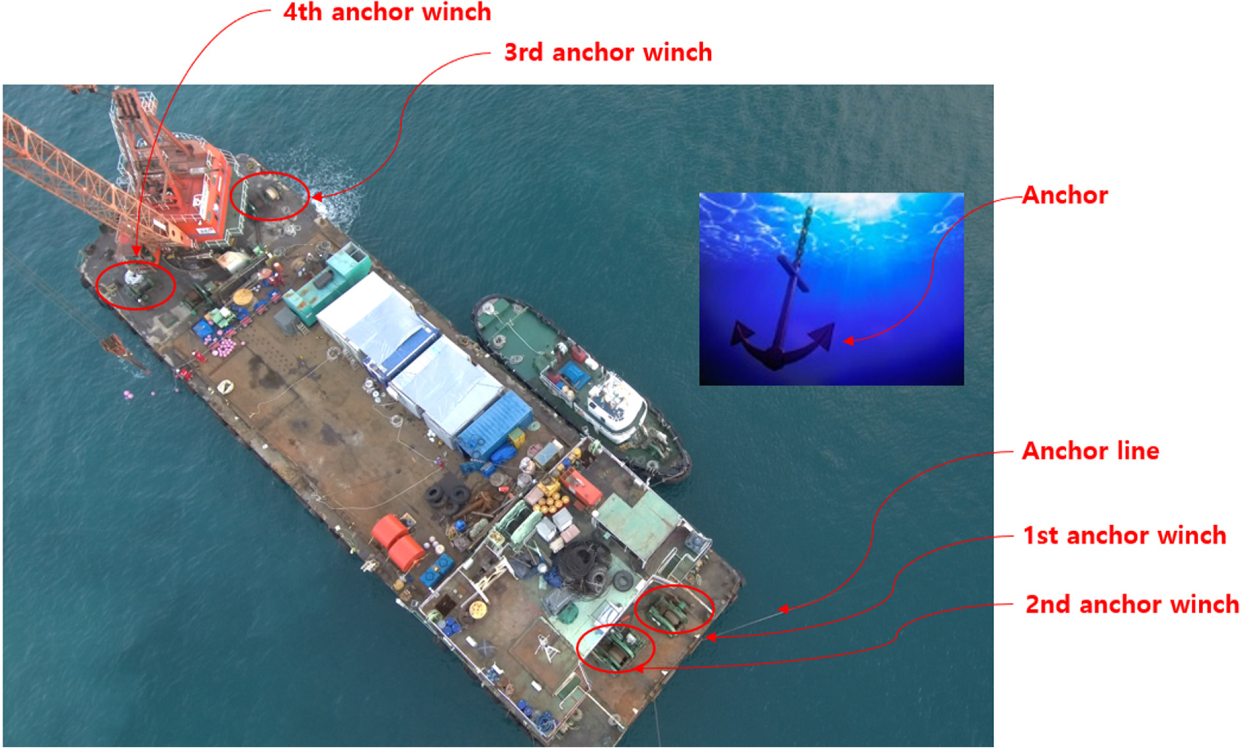
Barge anchor system

Method of moving a barge using anchor winches

Crane and cable handing system
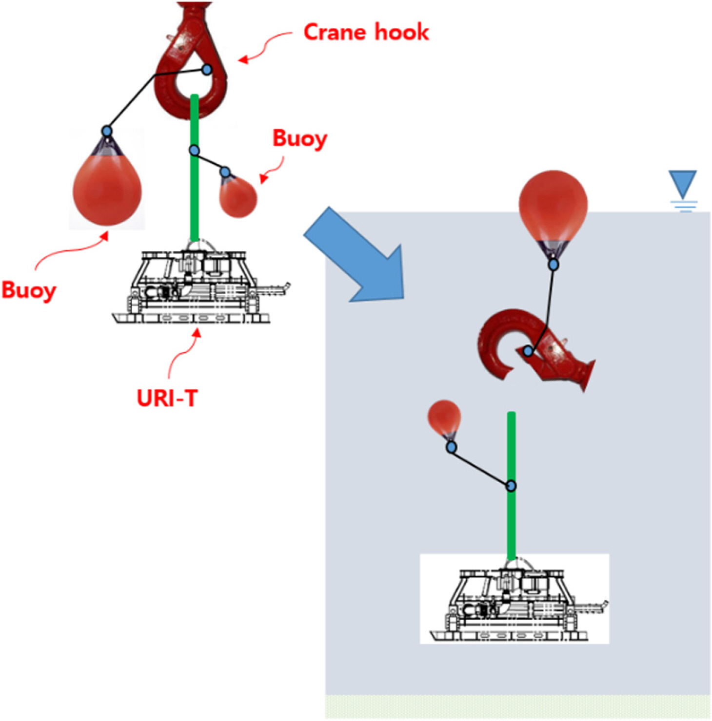
Automatic raveling device
Table 3 below compares the operational stages of an ROV when using a DP vessel to those when using a barge. Details for each stage of the barge operation are described in the following chapter.

Comparison of operating an ROV with a DP vessel and a barge
3.3 Operational Scenario of an ROV Trencher using a Barge
The operational scenario of an ROV trencher using a barge follows the same general sequence as the general ROV trencher operation, but the details of each step differ, as shown in Fig. 8.
Launch of the ROV trencher: A 20-mm wire is connected to the ROV trencher and the redundant barge winch to prevent loss in case of emergency. The umbilical cables are marked with colors at intervals of 5 ∼ 10 m to allow for continuous monitoring of the looseness of the cable. A connecting rope and an automatic unraveling device are installed on the ROV trencher and the crane hook, respectively, and the ROV trencher is launched on the water surface using the crane. During this step, the length of the umbilical cable must be continuously adjusted using the cable handling system. The ROV trencher sinks by its own force as it is released from the crane by the automatic unraveling device, and it slowly comes to rest on the seabed using the propulsion system. After the ROV lands at a given depth, its position is monitored by the onboard remote control system using the USBL and Quincy systems.
Position detection of pre-laid cables and pipelines using the cable and pipeline detection system (TSS350 and TSS440): While the ROV trencher tracks and lands over the pre-laid cables and pipelines, the anchor winch is used to keep the umbilical cable as straight as possible while the ROV trenches moves below the barge. The length of the umbilical cable is adjusted using the cable handling system.
Cable and pipeline burial and post-lay survey: While the burial and post-lay survey task is in progress, an anchor winch must be used to follow the movement of the ROV trencher, and the length of the umbilical cable must be adjusted using the cable handling system.
ROV trencher recovery: In the reverse order of the launch process, the propulsion system of the ROV trencher is used to elevate it to the water surface, and the umbilical cable is wound using the cable handling system. The connecting rope of the ROV trencher and the crane hook is connected by the deck management manager. At this time, the ROV trencher must maintain a constant depth and position. In particular, it must not float underneath the barge. Once connected to the crane hook, the ROV trencher can be retrieved onto the barge using the crane.
Operating scenario for an ROV trencher using a barge
4. Application to Buried Construction Sites
4.1 Overview of the Construction on the Water Supply in Yokji-do
The ‘Construction works of water supply in Yokji-do’ is a project that was carried out to expand the water supply area of the water purification plant in Yokji-do and to secure the future water supply and supply capacity. The Korea Offshore Company (KOC), a participating company in the ‘Site demonstration and commercialization of the developed heavy-duty ROV’ project, constructed the water supply pipe connections between the islands as part of this project. The water supply construction zones ‘Yokjido-Nodaedo’ and ‘Yokjido-Yeonhwado’ are 2.1 km and 5.4 km long, respectively, as shown in Fig. 9. Since the bottom of the seabed in the ‘Yokjido-Nodaedo’ zone is mainly dense sand and rock, the URI-T was only operated on part of this zone. The URI-T mainly performed the burial task in the ‘Yokjido-Yeonhwado’ zone, which has a soft and muddy seabed. This zone is about 2.5 m deep on average, and the burial task was conducted on 4.6 km of the total 5.4 km as the bedrock at the begnning and end of the zone were excluded. The burial depth was set to be at least 1.8 m from the top of the pipe to the seabed. The buried water supply pipe shown in Fig. 10 is about 300 mm thick, which includes two water supply pipes, a case to protect them, and a frame connecting the two cases.

Overview of the Yokji-do water supply construction work
Water supply pipe
4.2 Burial of the Yokji-do Water Supply Pipeline using a Barge
For the burial task in this zone, the 4000p barge Lamir and 72-ton tugboat Changyoung were used. The equipment was placed on the Lamir as shown in Fig. 11. A 160-ton class crane was installed for launch and recovery along with two 20-ton class anchor winches, two 30-ton class anchor winches, a 5-ton class auxiliary winch, and a 500-m long anchor. A 1000-kW genset generator was used to supply power to the URI-T. The office van space was used to observe the work conditions and for meetings, and the spare van was used to store work tools.
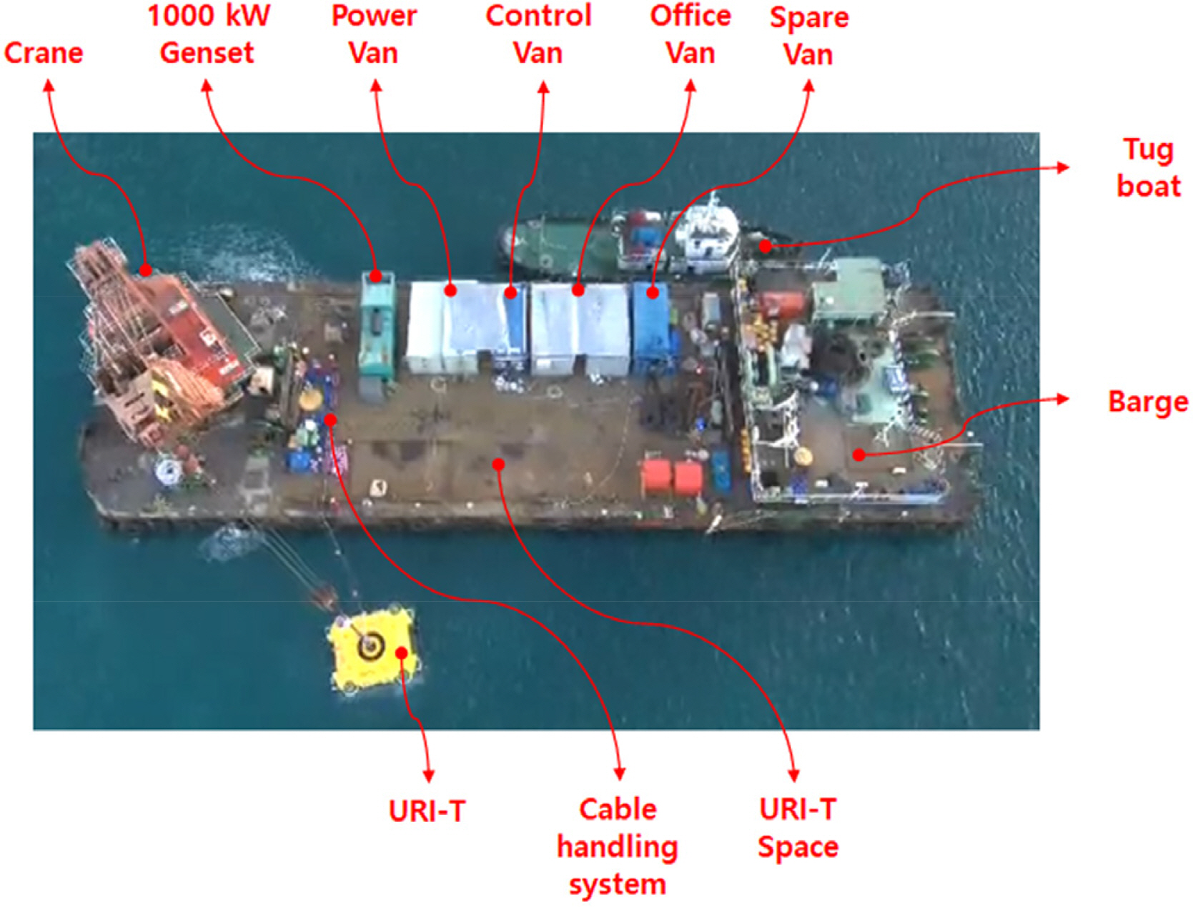
Equipment arrangement plan on the barge
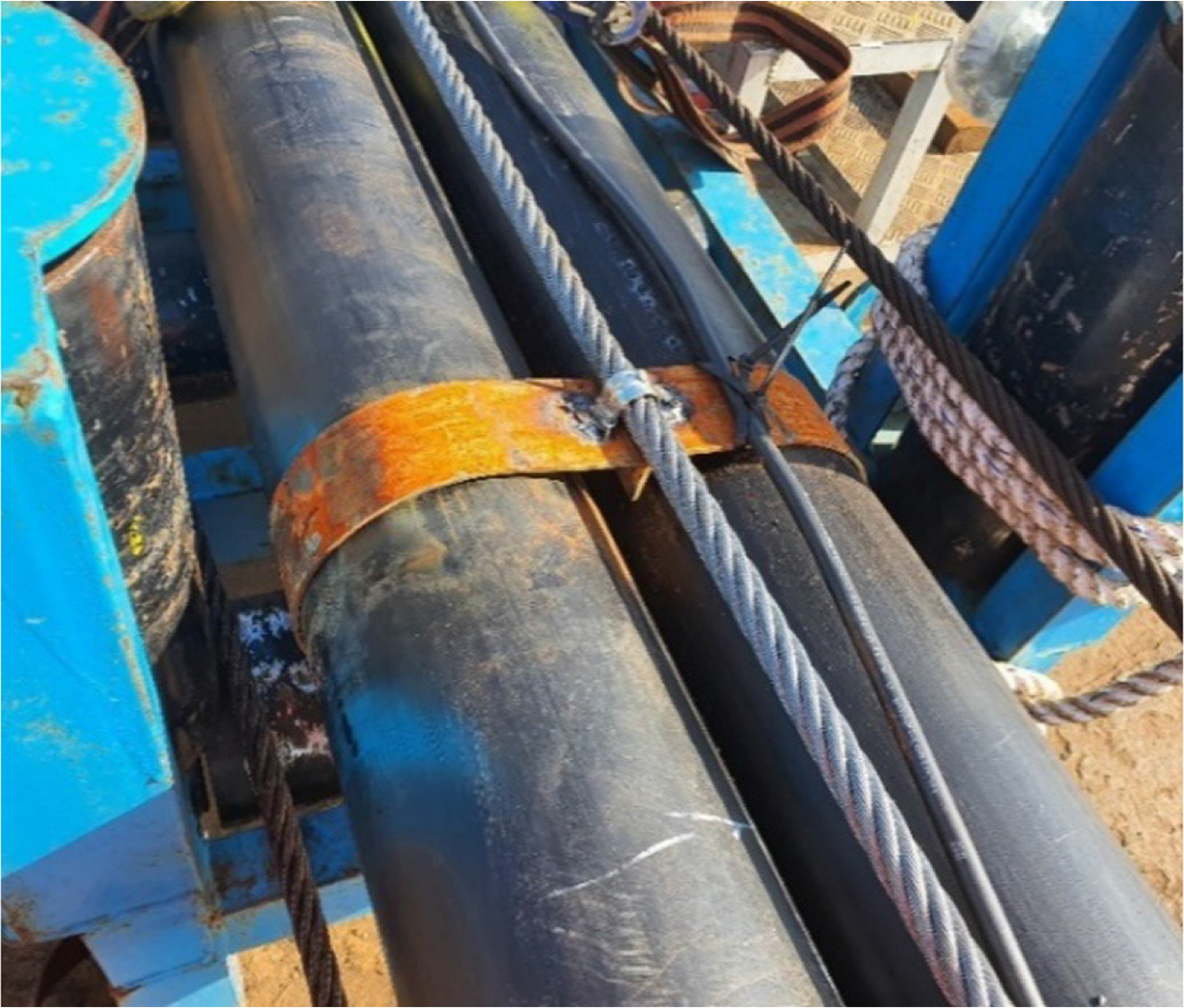
The water pipe burial work was conducted in consideration of site safety according to the scenario described above. Depending on the material and depth of the seabed, the burial was carried out 2 ∼ 4 times, with an approximate daily burial length of 200 to 600 m. Since the workg environment is near an actual fishing village, as shown in Fig. 12, there were incidents of fishing gear, such as ropes, buoys, and fishing nets, getting caught on the platform frame and thruster during the burial, resulting in damage to the frame. There was also damage to the jetting arm and safety rope winding the platform frame caused by operational errors. These errors were responded to immediately and remedied at the site, and the burial was completed.
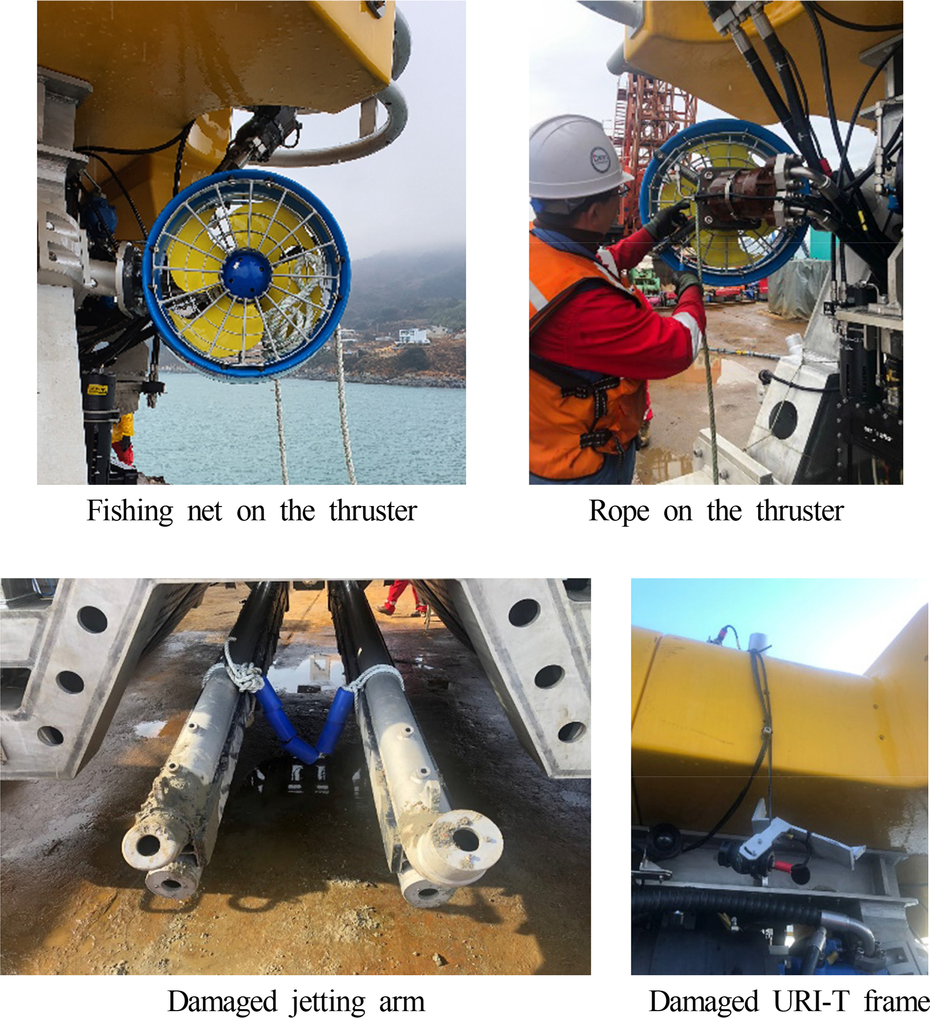
Damage to the URI-T
4.3 Results of the Yokji-do Waterworks Pipeline Burial
Results of the pipeline burial in the Yokjido-Yeonhwado zone are illustrated in Figs. 13 and 14. The burial task was performed over a distance of about 400 m from a point 480 m away from Yokji-do. The average burial depth in this zone was 1.84 m, which met the target depth of 1.8 m. This indicates that the proposed ROV trencher operation method using a barge is applicable to actual work sites.

Results of burying the pipeline
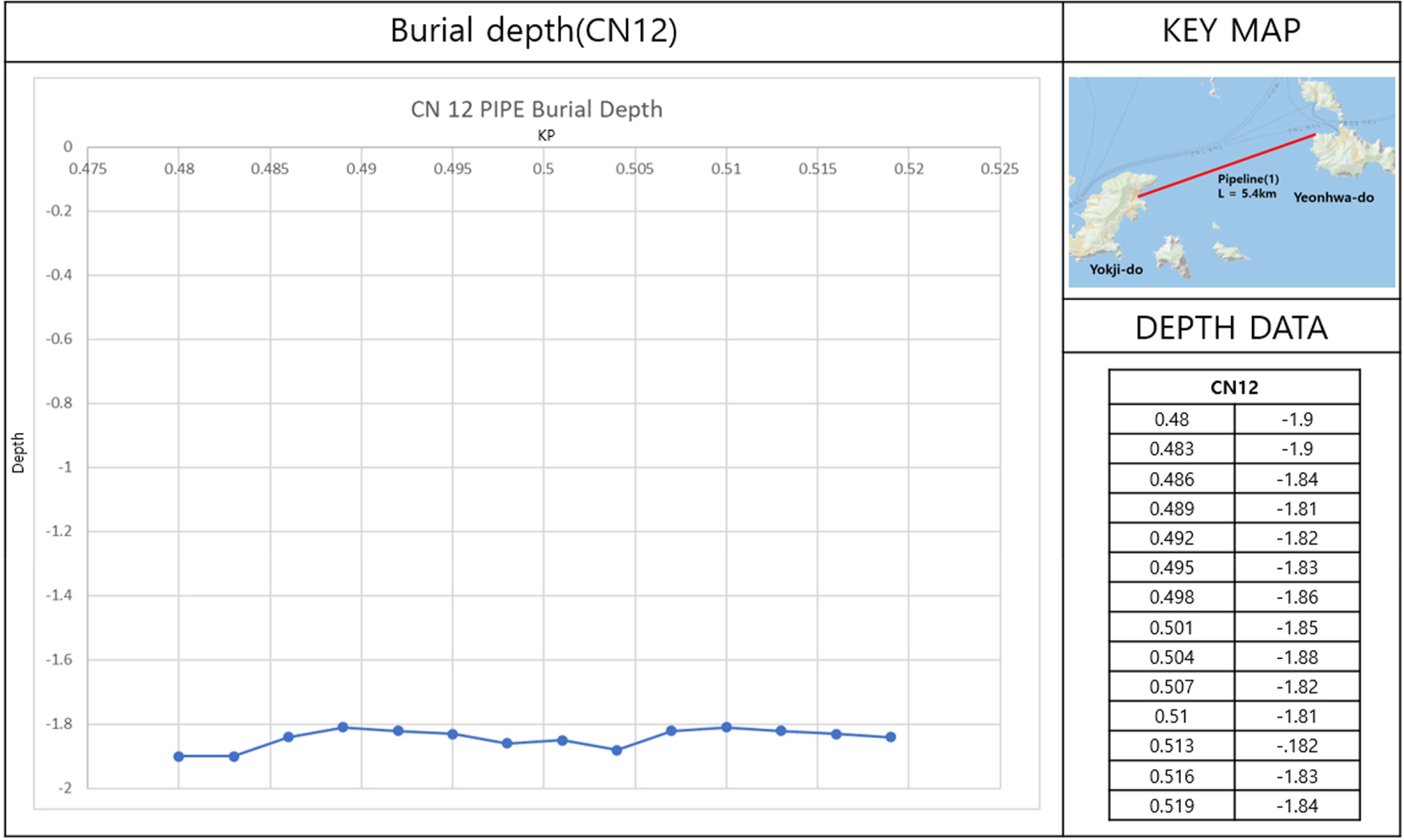
Burial depth results
5. Conclusion and Future Plans
In this paper, we proposed an ROV trencher operation method using a barge as a method that can be applied for burial construction on the domestic coast, in particular to short construction zones with an urgent schedule and low construction cost, and the applicability of the proposed operation method was verified. One disadvantage of the proposed method is that the launch and recovery and burial operation stages are complicated when compared to the method using an existing DP vessel, resulting in lower operational efficiency and operational stability. However, the proposed method can reduce the manpower required for the operation of the ship and ROV trencher as well as the ship rental and operating costs and can facilitate adjusting the working hours and schedule. It thus provides significant benefits in terms of the construction cost and scheduling for construction such as the water supply in Yokji-do. Going forward, we are in the process of securing a gas pipeline burial project in Vietnam (planned in August 2020), and modification and supplementation (2020.02 ∼ 2020.06) of the URI-T are underway accordingly. In addition, we are attempting to win bids for construction work on the domestic coast.
Acknowledgements
This paper relies on research conducted by the Ministry of Oceans and Fisheries funded by the Ministry of Oceans and Fisheries with the support of the Korea Institute of Maritime Science & Technology Promotion in 2020 (Underwater Construction Robot Project for Marine Development, PJT200539).
Notes
USBL is an underwater positioning system using sound waves; the transmitter is mounted on top of the ROV trencher, and the receiver is installed and operated in the bottom of the ship.
Quincy is a program used to manage survey planning, data collection, data organization, volume calculation, and depth chart generation in marine navigation, positioning and surveying activities for ROV and AUV tracking and data collection purposes.