A Review of IOSS Design Standardization Technology for Aluminum Alloy Handrail of Offshore Platform
Article information

Abstract
The Integrated Offshore Standard Specification (IOSS) involves Korean shipyards, classification societies, research institutes, the Korean industrial society, engineering companies, and oil companies with the objective of reducing costs and risks without compromising safety in international offshore engineering procurement construction (EPC) projects using new standardized bulk components and qualification procedures. The activities of the IOSS include the analysis of the existing rules and regulations to achieve the best standardization, which is reflected in the best practices, and minimize the variables in regulations and rules. In addition, a standard inventory of shapes and dimensions, referred to as specifications, is proposed in the IOSS. In this paper, the aluminum tertiary standardization part (IOSS S102-1/2 S104: Specification for Structural Tertiary Design) is presented with the details of the procedures, background reviews, and cost-benefit analyses of the design and verification methods for standard designs in the IOSS standardization items. Based on the cost-benefit analysis, the application of standardized aluminum tertiary items to offshore projects has significant advantages in terms of maintenance and repair compared to the carbon steel tertiary items utilized in current industrial practices.
1. Introduction
The demand for liquefied natural gas (LNG) is continuously rising owing to stricter environmental regulations and unstable oil prices. To satisfy this demand, various types of LNG production facilities are being built. LNG storage facilities must be able to process cryogenic/high-pressure and liquefied gas; as such, diverse safety designs are being reviewed, including not only the structural strength in extreme operating environments but also the application of risk-based design techniques concerning life, environment, and property.
In floating LNG production facilities in particular, unlike facilities on land, the weight of the upper structure is limited considering the storage capacity and buoyancy of the lower floating structure. Researchers are making various attempts to reduce weight. However, in the case of the primary and secondary members that require strength and toughness to withstand a variety of extreme environments and operating conditions, precise material and strength design standards must be applied for structural safety, and there are difficulties for achieving innovative weight reduction. As the tertiary member is a non-strength member, aluminum alloy steel, stainless steel, nickel ore, and composite materials are being investigated as effective alternatives to carbon steel in terms of functional requirements and large-scale use.
Among these materials, aluminum alloy is widely known as an eco-friendly material with a high weight-to-strength ratio and excellent corrosion resistance and workability. Its strength has been enhanced, gradually increasing its applicability as a structural material. However, aluminum tertiary members lack standardized product production and design criteria and quantitative comparisons with carbon steel members. Consequently, owing to differences in manufacturers’ product designs, there are many difficulties in applications to actual projects, and the application cases are extremely limited.
Accordingly, to strengthen the shipbuilding industry’s technological competitiveness and gain market advantages, researchers have expressed the need for a systematic design standardization, identifying the trends and devising response strategies regarding international standardization, and developing standards for eco-friendly ships in the future (Cha, 2009; Kim et al., 2009). In addition, the studies have identified the major factors that weaken the price competitiveness. They are the low localization rate of key equipment and materials caused by limited business models, an industrial structure focused on offshore platforms, and inadequate technical capabilities such as in front-end engineering design (FEED). These have been consistent issues in the Korean offshore facility industry.
In terms of technology policies for strengthening the offshore facility industry’s competitiveness, there are efforts to secure FEED engineering technology and source technology for key equipment and materials, cultivate talent, and develop supply and diffusion business models. For this purpose, it is necessary to create a new market for domestic shipbuilding and marine equipment companies in ccooperation with the International Standards Organization (ISO) in connection with the International Maritime Organization (IMO), which is becoming a topic of international discussion, and to increase overseas marketing to enhance export competitiveness (Oh, 2017).
Accordingly, as part of the Integrated Offshore Standard Specification (IOSS) derived through a joint industrial research of the unified offshore standardization bulk package used by offshore facilities, this article presents the contents of the aluminum tertiary member design specifications (IOSS, 2019) and the results of the conducted applicability analysis.
2. Standardization of Aluminum Alloy Tertiary Member
2.1 IOSS Standardization Process
More than 200 shipbuilding-related items are registered as international standards (ISO); however, offshore structures have relatively few registered standards (ISO-TC67 / SC7) compared to other areas, and none are registered in the Korean Standard (KS). This is because the design standards for offshore platforms must apply project specifications that integrate not only the requirements of the installation area but also international standards and ordering company/class requirements. Moreover, even for structures being operated in the same area with the same ordering company, different specifications are applied due to complex and inconsistent project requirements.
Therefore, in spite of standardization attempts applying various designs, there are difficulties in establishing standardizations owing to inconsistency between the standardization leader’s goals and the direction of the participating companies. Accordingly, as shown in Fig. 1, this article presents a design standard plan, which is the result of establishing rational design standards through revision and reflection of the standards, defining the standardization items, and analyzing the differences in the rules and regulations applied to each item. It also presents an analysis-based standard proposal and a review of the technical review group/technical advice group (TRG/TAG) standards (Ellingsen et al., 2018).
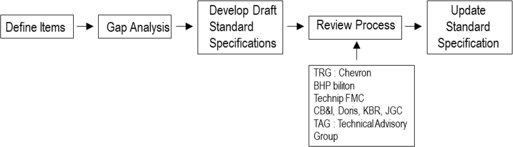
IOSS Process
2.2 Review of Standardized Items and Regulations
First, this study selected the items requiring standardization for the bulk materials used in offshore platforms considering the following three aspects: (1) possibility of cross-use through standardization, (2) possibility to solve problems that chronically arise in projects, and (3) comprehensive satisfaction of various rules and regulations. Based on these three aspects, the priority for development was set as presented in Table 1.
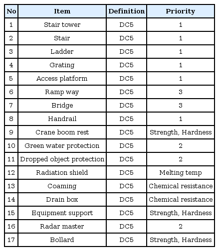
Priority of development for IOSS activity
Second, in relation to the items requiring standardization, this study examined and analyzed various rules and regulations of the tertiary members applied to large offshore platforms manufactured within the past decade. Among the tertiary members of offshore platforms, four essential items used in large quantities for safety and convenience are handrails, stairs, vertical ladders, and gratings.
Furthermore, the relevant rules and regulations applying to these four items were classified in accordance with the international rules and regional regulations listed in Tables 2–3 (ISO, 2001a; ISO, 2001b; ISO, 2001c; ISO, 2004; NORSOK Standards, 2004; NORSOK Standards, 2006; ANSI/ASSE, 2007; ANSI, 2000; Australian Standard, 2013).
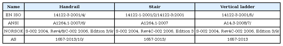
Identified standards

Identified regulations
Therefore, to secure the persuasiveness of the integrated standard and a correct direction for the standard, this study performed a more detailed analysis of the related regulations and rules. Key design factors in terms of function and work safety were derived based on each rule and regulation, as presented in Tables 2 and 3, and the essential evaluation items for design are included in Table 4 with a detailed analysis.
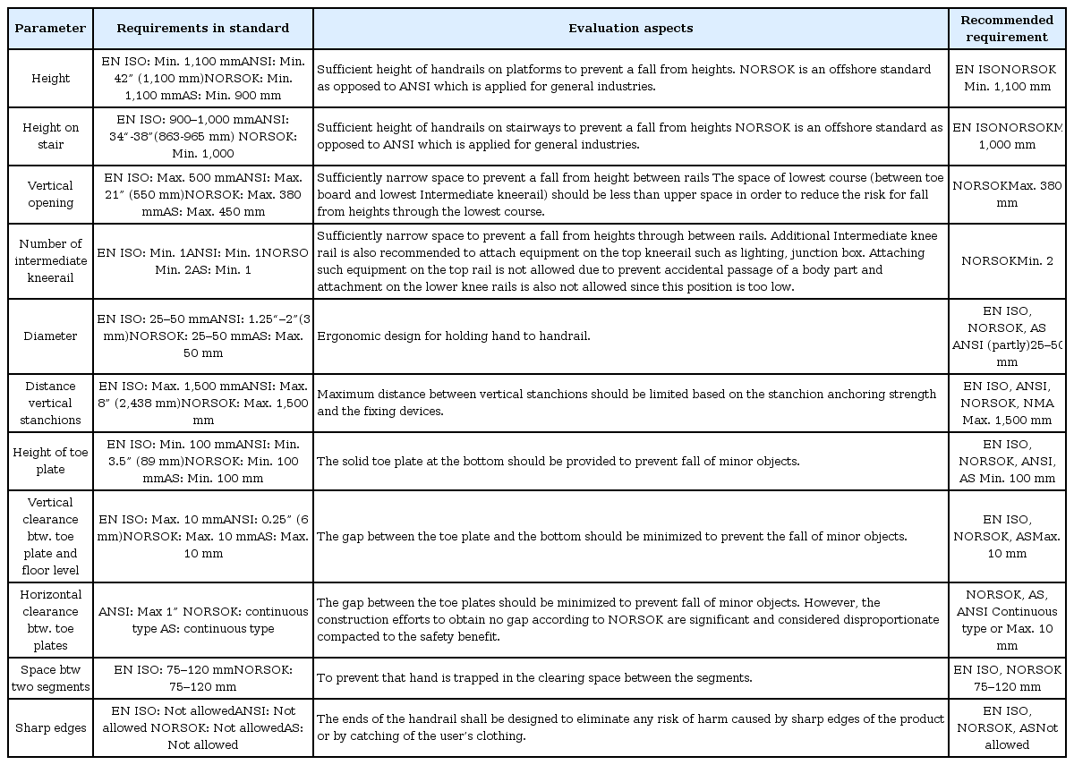
Evaluation of requirements for handrails (continuation)
According to the detailed specification analysis, in general, the classified rules and regulations did not differ significantly. Regarding handrails, which have the highest proportion of use and directly impact safety, there were some differences in the applied rules and regulations, as presented in Table 5, including handrail height, quantity of the intermediate kneerails, and toe plate height. This is primarily because the existing design methods were applied or special additional conditions of the project were applied based on international standards (ISO) (Ellingsen et al., 2018).

Comparison of requirements of standards and regulations for handrail
As shown in Fig. 2, the application rate within the past five years of the rules and regulations commonly used in offshore platform construction was simultaneously reviewed, and the handrail height was determined to be 1,100 mm considering the worker’s safety and work convenience. Table 6 presents a planned standard that comprehensively satisfies the existing related regulations of NORSOK S-002 (NORSOK Standards, 2004) and ISO 14122-1–4 (ISO, 2001a; ISO, 2001b; ISO, 2001c; ISO, 2004).
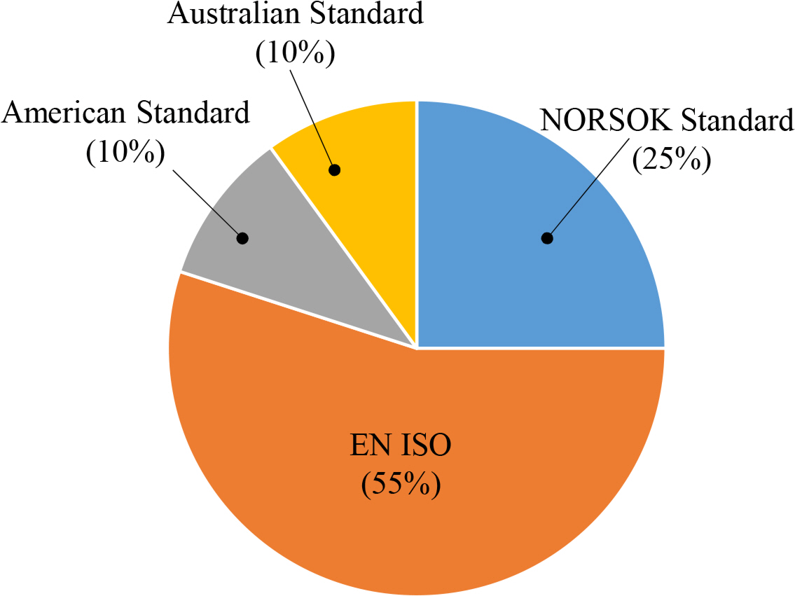
Statistics of percentage to apply standards for offshore projects during last five years
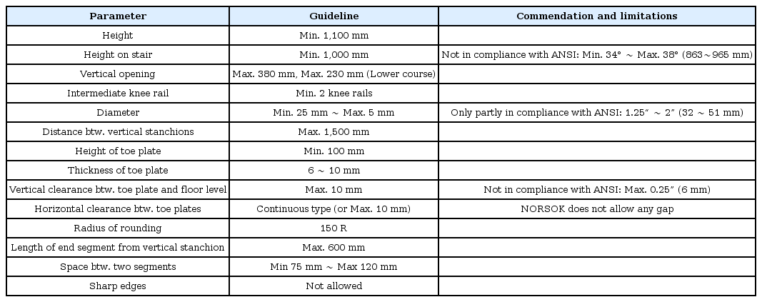
Recommended dimensions for handrails
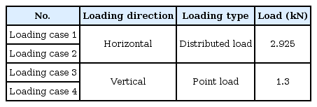
Test condition of handrail
To minimize analytical errors in design and production by engineering companies, oil companies, and classification societies, which mainly arise when applying the rules and regulations, the standard was devised to avoid confusion during design, manufacturing, and inspection by providing accurate recommended guidelines and reference designs, as those shown in Figs. 3 and 4 (IOSS, 2019).

Specification for handrail design
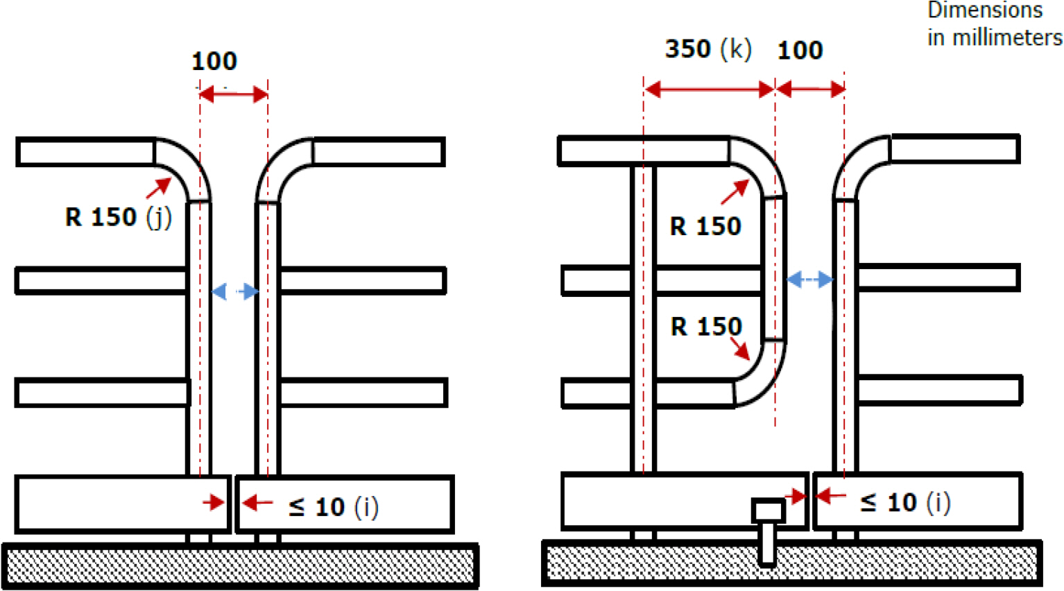
Specification for handrail design
2.3 Design Applicability Analysis
In the third step, to examine the applicability of the standardized design based on the results of applications, this study reviewed the practical applicability of the verified standards in groups selected as TRG/TAG standards. The new standard established and implemented a systematic review process that minimizes risks such as delivery delays and deficits in real projects, as shown in Fig. 5, thus enhancing its completeness.

IOSS standardization review process
Each review process is divided into the proposal of the standard by the W/G members that comprise the classification societies, associations, and shipyards participating in the standard; a primary review by the W/G internal TAG members; and a secondary review by the major oil and engineering companies that are TAG members, thereby improving the quality of the devised standard and maximizing its integration.
2.4 Experimental Analysis of Handrail Standardization
To investigate the adequacy of the devised handrail design standard, this study performed an empirical experiment related to the test certification procedure of the product. In IOSS, the “Top mounted handrail in the case of inside coaming” was selected considering both the strength test procedure and strength characteristics required by the related regulations, and the applied load was determined considering the load conditions and safety factor defined in ISO and NORSOK.
Furthermore, an experimental test procedure was developed in which the experimental conditions for each member constituting the handrail were varied to investigate the structural safety that satisfies the use objective of the handrail, as shown in Fig. 6.
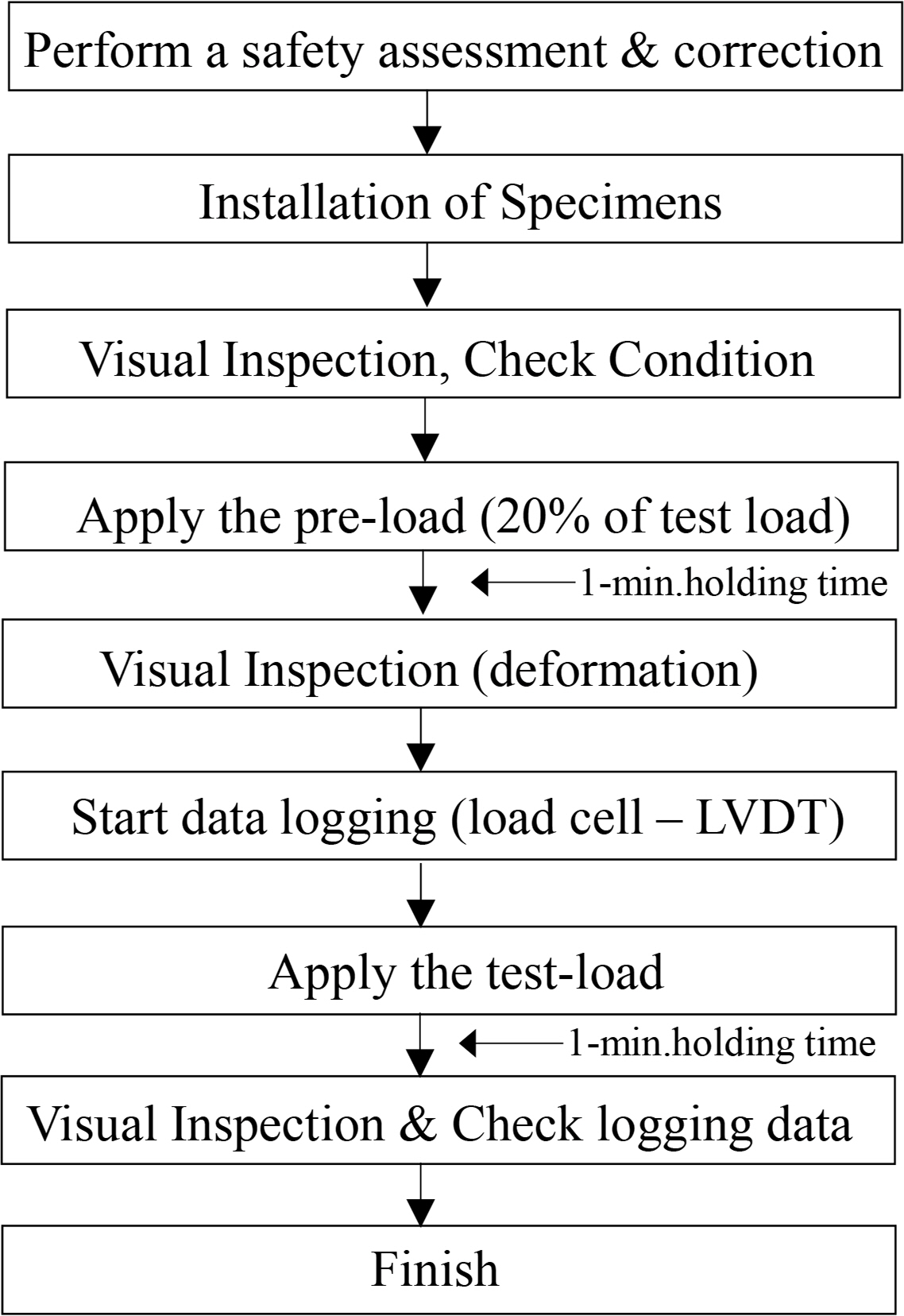
Experimental test procedure
As shown in Figs. 7–9, he distribution and concentration loads were applied to the top-rail, Stanchion and mid-rail of the specimen by connecting the load cell and the lever/chain block. This test were reflected in the standard test procedure through schematics of the specimen top-rail, stanchion, and mid-rail.

Distributed load at a stanchion (Loading Case 1)
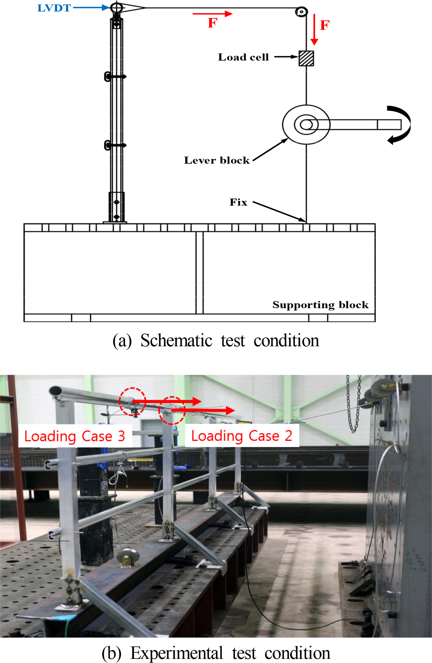
Horizontal load at a stanchion (Loading Case 2 and 3)
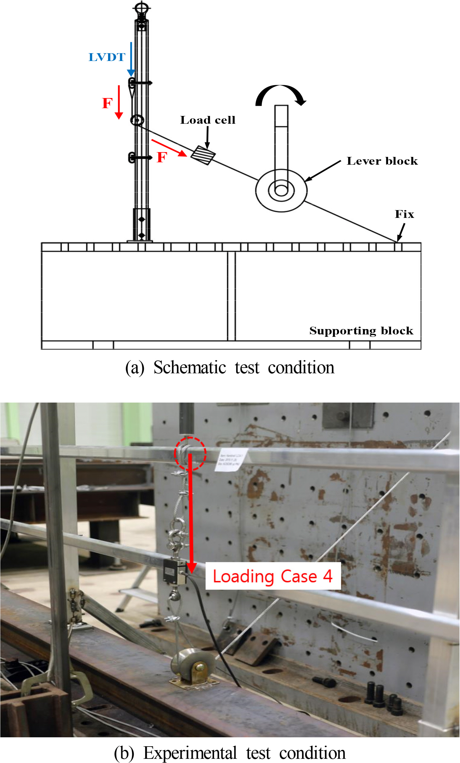
Vertical load at a midpoint of handrail (Loading Case 4)
As presented in Table 8, in terms of the test criteria, the occurrence of permanent deformation and cracking is not allowed and a maximum deformation of 30 mm under the test load conditions were proposed as the evaluation criteria, with reference to the maximum allowable strain and permanent strain defined in ISO and NORSOK.

Allowable criteria of the handrail under test condition
For the experimental analysis of the standardization product, this study conducted an empirical verification of the handrail tertiary member standard, as shown in Figs. 8(b)–9(b). In particular, for products designed based on the manufacturer’s numerical analysis, improvement plans reflecting the on-site installation environment and various manufacturing defects are being derived through experimental verification and are under review to be reflected in the standard.
In addition, regarding ISO and NORSOK standards based on the existing carbon steel, in the case of Loading Case 4, it was impossible to meet the different requirements of each project ordering company (e.g., safety chain fastening conditions for workers) through the existing individual design standards. However, it will be possible to effectively meet the design/production company requirements by reflecting them in the standardization product through the clear comparison and analysis of this experimental analysis method.
Accordingly, based on the standard test procedure and empirical test results, evaluation methods not only of the handrail but also of tertiary member item products derived from the JIP (Joint industry project) are being reviewed and reflected in the IOSS design standards. This series of processes will serve as an important base technology for the technical completeness of new standards, improvements in product reliability, and enhanced technological competitiveness of manufacturers.
3. Cost-effectiveness Analysis
The developed standardization was applied to an actual project to verify its effectiveness regarding project cost reduction and whether it secured competitiveness. To this end, a large offshore platform manufactured and delivered in Korea was analyzed. Accordingly, a comparative analysis of the weight reduction effect and cost (material cost, manufacturing cost, maintenance cost) was conducted assuming that the IOSS aluminum standard was applied to the carbon steel handrail, stairs, and vertical ladders used in the project.
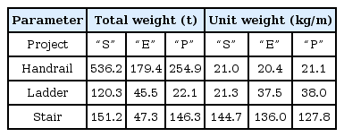
For comparison of the aluminum and carbon steel tertiary members, the carbon steel and aluminum unit weights were calculated as listed in Tables 9 and 10. Regarding the criteria, the handrail was calculated assuming it was continuous, with three rails, and excluding the stiffener weight, the vertical ladder was calculated without distinguishing between cage and non-cage ladders, and the stair was calculated based on the tread (38 × 5, pitch 30), excluding the handrail weight.
Carbon tertiary items total/unit weight
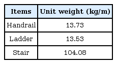
Summary of the unit weight for aluminum tertiary items
For the maintenance costs of the aluminum tertiary members, the baseline data, the manufacturing/maintenance costs of the aluminum and carbon steel tertiary members were calculated based on an precedent research (Muzathik et al., 2012), as shown in Table 11, and compared.
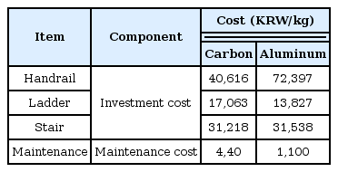
A comparison of the carbon and aluminum cost according to outfitting items
Table 9 shows the comparison of the total and unit weight for the handrail, ladder, and stair applied in three large projects “S,” “E,” and “P.” Given the shape of the aluminum tertiary members, as aluminum is lighter than carbon steel and minimizes welding, the weight was reduced by an average of 40%, as presented in Table 12.

A comparison of the carbon and aluminum weight according to outfitting items
Table 11 compares the cost per unit weight of the aluminum production cost and the cost of the carbon steel tertiary member material + manufacturing cost + hot-dip galvanization cost. Although the initial material cost for aluminum exceeds that of carbon steel, as aluminum does not require hot-dip galvanization and welding, when compared by item, the cost of the aluminum tertiary members was similar to that of carbon steel members, or even lower. Moreover, considering the maintenance period, as shown in Fig. 10, aluminum is more cost-effective than carbon steel after an average of 5.7 years.
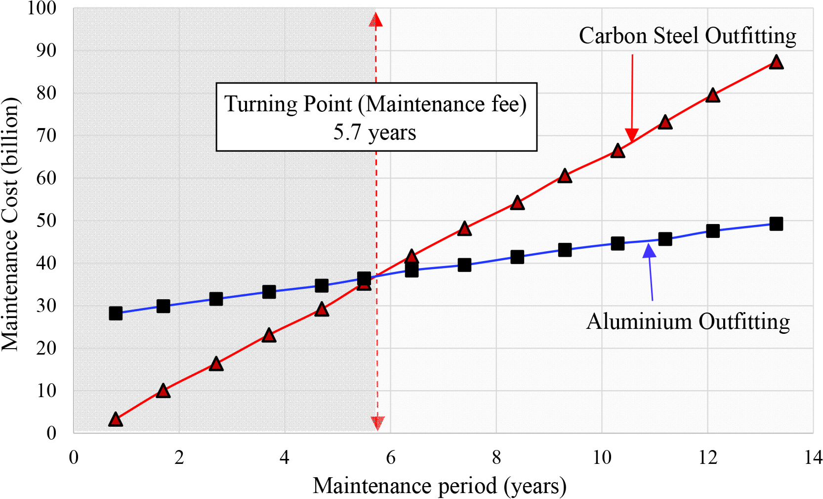
A relationships of between cost and maintenance period according to materials (carbon steel and aluminum)
A comprehensive analysis of the above results demonstrated that the aluminum tertiary members designed and manufactured using the technical standard can be an alternative to the existing carbon steel tertiary members in offshore platforms.
4. Conclusion and Discussion
As part of the IOSS obtained through a joint industrial research of the unified offshore standardization bulk package used by offshore facilities, this article presents the contents of the aluminum tertiary member design specifications (IOSS S102-1/2 S104) (ISSO, 2019) and the results of a design standardization and applicability analysis based on the handrail, a tertiary member that uses aluminum alloy. The following detailed conclusions were drawn.
The major contents of the international tertiary member standardization can be confirmed, which should serve as useful data for similar future projects by specifying the effect of application.
The devised aluminum tertiary member standard design was applied to a recently manufactured large offshore project and analyzed. According to the results, the material cost of aluminum was more than twice that of carbon steel, raising concerns about increased project costs. However, when calculating the actual tertiary member costs by unit weight and incorporating the material, welding, and hot-dip galvanization costs, the cost of aluminum was equal to or less than that of carbon steel.
In comparison to carbon steel, aluminum barely has maintenance costs, and it does not require paint. Thus, aluminum showed lower costs than carbon steel after an average of 5.7 years, giving it sufficiently high applicability.
Through the participation of relevant Korean equipment companies in the standardization process, this will serve as an important base technology not only for the technical completeness of new standards, but also for improvement in product reliability and enhanced technological competitiveness of manufacturers.
In addition, the IOSS is being applied primarily in shipyards for real projects, and preparations are underway for its reflection in international standards for offshore structures. Finally, a working committee under ISO TC67 was newly established, and a draft international standard (DIS) for reflection in ISO is currently in progress.

Acknowledgements
This article utilized some content from UBS JIP and is the result of a research conducted under the Encouragement Program for the Industries of Economic Cooperation Region of the Ministry of Trade, Industry and Energy and the Korea Institute for Advancement of Technology (Task No.: P0002308).