Estimation of Penetration Depth Using Acceleration Signal Analysis for Underwater Free Fall Cone Penetration Tester
Article information

Abstract
A track-type underwater construction robot (URI-R) was developed by the Korea Institute of Ocean Science & Technology. Because URI-R uses tracks to move on the seabed, insufficient ground strength may hinder its movement. For smooth operation of URI-R on the seabed, it is important to determine the geotechnical properties of the seabed.
To determine these properties, standard penetration test (SPT), cone penetration test (CPT), and sampling are used on land. However, these tests cannot be applied on the seabed due to a high cost owing to the vessel, crane, sampler, and analysis time. To overcome these problems, a free fall cone penetration tester (FFCPT) is being developed.
The FFCPT is a device that acquires the geotechnical properties during impact/penetration/finish phases by free fall in water. Depth information is crucial during soil data acquisition. As the FFCPT cannot measure the penetration depth directly, it is estimated indirectly using acceleration. The estimated penetration depth was verified by results of real tests conducted on land.
1. Introduction
The Korea Institute of Ocean Science & Technology has developed the track-type underwater construction robot, URI-R. As shown in Fig. 1, the URI-R is a track-type equipment that moves and excavates on the seabed and can be used up to a maximum depth of 500 m. It can trench up to depth of 2.5 m and width of 0.6 m. The weights of the URI-R in air and water are 38 t and 32 t, respectively. Insufficient ground strength of the seabed can make it difficult to move or trenching work. Therefore, it is critical to obtain the geotechnical properties of the seabed for the smooth operation of the URI-R.

Underwater construction robot URI-R
On land, in-situ or lab tests are performed using samples to determine the geotechnical properties (Jang, 2015). For in-situ tests, standard penetration tests (SPTs) or cone penetration test (CPTs) are mainly used. The SPT determines the geotechnical properties by measuring the hit count required to cause the penetration of a rod to a depth of 30 cm through the repeated falling of a hammer (standard weight of 63.5 kg) from a height of 76 cm from the knocking head, which is the hitting point (Lee, 2008). A CPT measures the tip resistance, sleeve friction, and pore pressure while continuously penetrating a cone probe sensor into the ground at a constant rate of 20 mm/s. The test is terminated when penetration becomes impossible due to contact with a hard layer (Rogers, 2011). When sampling is required, samples are acquired from the test site using a sampler and then analyzed in the laboratory. When the above-mentioned methods, which are conventionally used on land, are used to determine the geotechnical properties of the seabed a high cost is incurred because of the use of a vessel, crane, and sampler and a longer analysis time. Moreover, various issues such as the applicable depth also need to be considered.
To overcome these problems, Marum (Stegmann et al., 2006) and Rolls-Royce (Brown et al., 2010), among others, have produced free fall cone penetration testers (FFCPTs). The FFCPT is a device that was developed by applying the CPT for land; it determines the geotechnical properties during impact/penetration/finish phases by free fall in water. The mobility of the URI-R can be determined instantly because the FFCPT and its ancillary equipment are smaller than the equipment used on land, the measurement data can be acquired on site and the geotechnical properties can be analyzed after recovering the device from the seabed to the ship. Furthermore, when a FFCPT for deep water can be conveniently used to acquire the non-drained shear strength, which is required for the design of deep sea offshore plant structures (Woor et al., 2018). Therefore, the Korea Institute of Ocean Science & Technology is developing a FFCPT to determine the possibility of stable operation of URI-R in the field.
To determine geotechnical properties, various ground data by the penetration depth is required. On land, the penetration depth and ground data can be obtained using various methods such as encoder, linear variable differential transformer (LVDT), and so on. However, it is difficult for the FFCPT to directly obtain the ground data synchronized with the penetration depth. Therefore, the penetration depth was indirectly estimated using acceleration signals, and the performance was verified by comparing the measurement and estimated depths through a land experiment.
2. Ground Penetration Behavior Characteristics of FFCPT According to Acceleration Changes
FFCPT is a device that determines geotechnical properties of the seabed by penetration depth, and it is critical to penetrate as deeply as possible and derive the penetrated depth. To achieve the maximum possible penetration depth of the FFCPT so as to maximize the falling inertia, it is advantageous to exclude components that interfere with free fall except the recovery wire (Shin et al., 2019). Furthermore, since it is difficult to directly measure the penetration depth of the FFCPT that collided with the seabed, we estimated it indirectly using the acceleration that acts in perpendicular direction to the ground. The acceleration a(t) generated by the FFCPT behavior can be converted to velocity v(t) and displacement s(t) through integration (Yang et al., 2016) as follows:
The time points for the integral section can be selected by 0 as at the monet of impact and tf as the final arrested time. In addition, when the selected acceleration integral section is reversed and integrated, v0 can be assumed to be a stopped state after penetration (v0 = 0) and v(tf) as the penetration velocity when the FFCPT hits the ground. When the calculated v(t) is reversed and integrated again, s0 can be assumed to be the depth at the moment when the FFCPT hits the ground and penetration starts (s0 = 0), and s(tf) as the final penetration depth after the penetration behavior finishes.
McCarty examined the ideal acceleration trend that occurs when an object collides with a random medium as shown in Fig. 2 (McCarty and Carden, 1962). The behavior of the object colliding with a medium appears in five phases: impact, penetration, initial finish, reaction, and final finish. In Fig. 2, the point where the acceleration slope changes sharply is the impact (phase 1). After impact, penetration (phase 2) starts, and the penetration velocity sharply decreases until the maximum acceleration occurs. In the section from the maximum acceleration to the initial finish, the penetration velocity decreases relatively slowly compared to that of the previous section; then, the initial finish (phase 3) occurs. After that, the object moves in reverse direction by the reaction (phase 4). After the first reaction, the object behavior can be changed depending on the properties of the medium, and lastly, the final finish (phase 5) occurs. The FFCPT (object) developed in this study penetrates (impacts) the seabed (medium) and finishes in the ground and can be expected to behave similarly to that shown in Fig. 2.

Acceleration event cases before & after impact
3. FFCPT Configuration
3.1 Mechanical Part
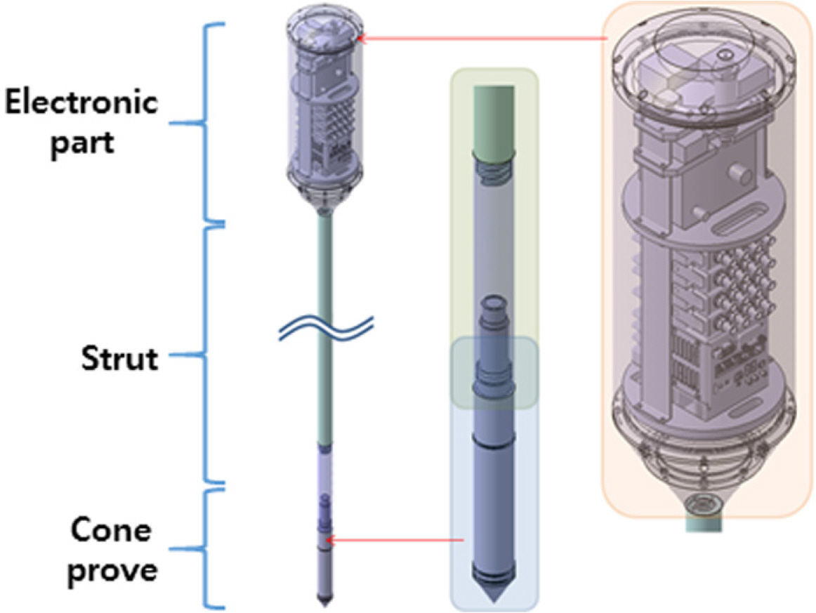
As shown in Fig. 3, the FFCPT is composed of an electronic part for data measurement and storage, a cone probe which is a sensor for measuring the geotechnical properties, and a strut which acts as a structure support interconnecting the electronic part and the cone probe. The strut can be extended in 1 m units and ranges from 1 m to 3 m.
Configuration of FFCPT
The electronic part is composed of a data acquisition (DAQ) device for signal measurement and data storage, a sensor and conditioner for measuring acceleration signals, a power battery, and a pressure sensor. Fig. 4(a) shows the assembly inside the electronic part. The pressure-resistant container in which the electronic part is mounted acts as a buoyancy material in the water. The buoyancy center of the total structure is designed to be higher than the center of gravity to achieve stability during the fall in the water. The distance between the buoyancy center and the center of gravity is 21 cm when the strut is 1 m, and 60 cm when the strut is 3 m. Fig. 4(b) shows the upper link, an intermediate structure that interconnects the electronic part at the top and the strut at the bottom. The upper link is a cone with a bottom diameter of 3.6 cm and a top diameter of 18 m. The impact from the strut is dispersed in the pressure resistant container. Fig. 4(c) and (d) show the strut and lower link, respectively. The strut is a hollow rod structure with a 1 m screw thread with a hole on the side of the rod so that the inside of the strut will be filled with water while immersed in the water. Once the strut is filled with water, the buoyancy change of the total structure can be minimized even if the strut length is changed. The lower link is an intermediate structure that interconnects the strut and cone probe, which have different thread shapes. The cone probe at the bottom is connected with the electronic part via a cable, and it also prevents the cable from breaking away under impact.
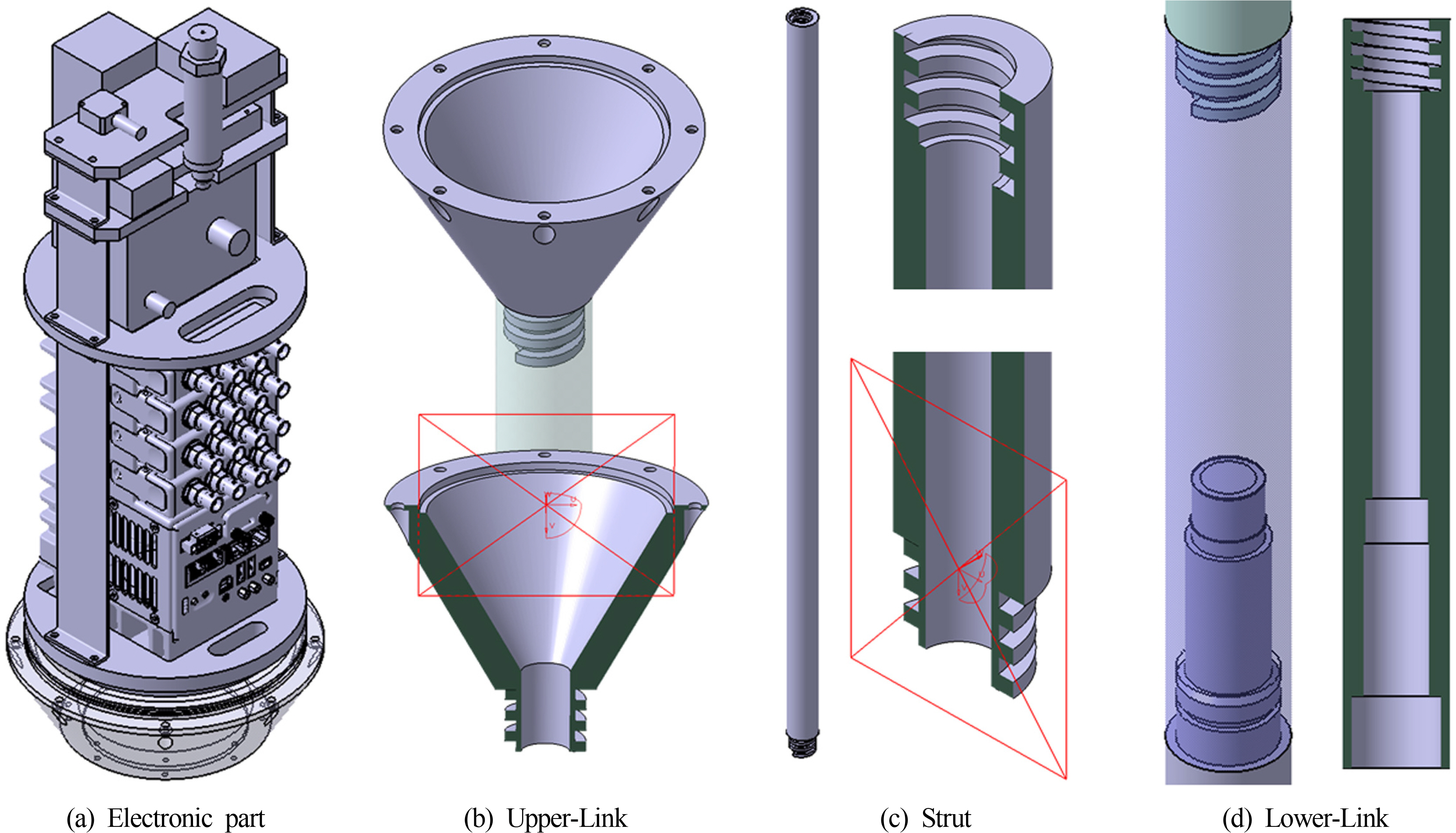
Detailed design of each components
3.2 Electronic Part
Sensors and the DAQ system were composed as shown in Fig. 5 to determine the geotechnical properties data as the FFCPT penetrated the seabed. The cone probe is a sensor complex for collecting geotechnical properties data and can simultaneously measure the cone tip resistance value, main surface frictional resistance, penetration gap water pressure, and slope. NI cRIO-9033 was used for the DAQ, PCB 3711B1150G for the acceleration sensor, and Omega PX409-750G10V for pressure sensor to measure the depth. To capture the accurate acceleration signals, an analog digital convertor (ADC) with 24 bit resolution was used, and a sampling frequency between 1.6 and 51.2 kHz was selected by the user. It can be used continuously for 8 h when fully charged using a 10,000 mAh battery.

Sensors and DAQ system
4. Experiment and Results Analysis
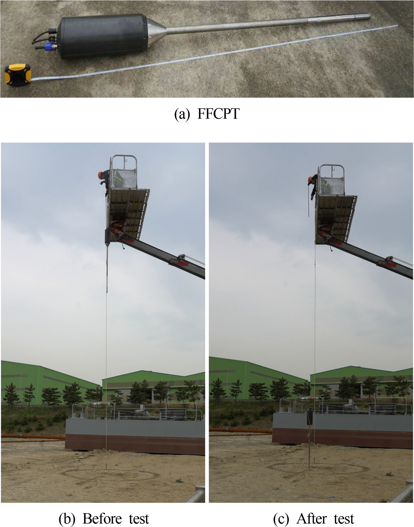
The estimated penetration depth performance of the FFCPT using acceleration signals was verified through a land experiment. There are two main differences between underwater and land experiments. First, a difference in the FFCPT terminal speed value occurs during the fall due to a difference in fluid density, which leads to a difference in penetration depth. However, the penetration process of the FFCPT after hitting the ground is identical to the process on land. Second, a strong horizontal force can be applied to the FFCPT during falling due to algae, etc. To verify this, an inclinometer was mounted in the FFCPT. Therefore, the slope of the FFCPT caused by a lateral force can be measured and the penetration depth can be estimated by reflecting it. To improve the precision of the experiment in this study, the FFCPT is set to discard the slope values exceeding ± 5° during ground penetration. The dominant behaviors of the FFCPT, however, are almost identical between performance on land and underwater. Therefore, the penetration depth can be estimated through land experiment before underground experiment. The experiment was performed on a landfill ground near the Pohang Underwater Construction Robot Complex Demonstration Center. As shown in Fig. 6, using a crane the FFCPT moved by a certain distance from the ground, after then it fell freely. The penetration depth was measured when the behavior of the FFCPT was finally stabilized after it hit the ground. Then, the FFCPT was pulled out from the ground and the data stored in the DAQ was sent to the computer and analyzed. The data analysis program was created using NI Labview and the behaviors of the FFCPT were analyzed using acceleration signals.
Estimation of penetrated depth test
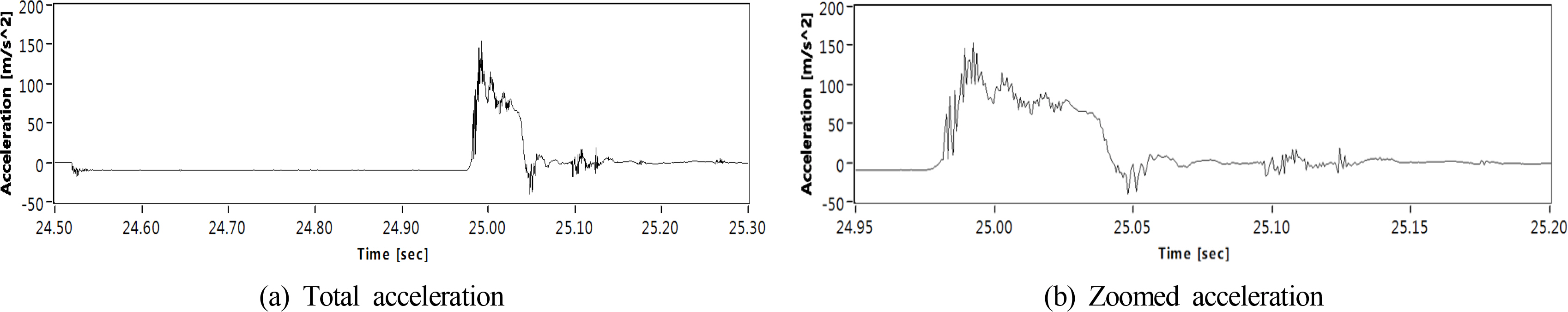
The acceleration signals captured from the penetration experiment of the FFCPT at 1 m height are shown in Fig. 7. The FFCPT started falling from 24.513 s and the acceleration was −9.8 m/s2. The impact started at 24.988 s, and the FFCPT penetrated the ground, showing a sharply increasing acceleration curve. The maximum acceleration recorded in this penetration experiment was 152 m/s2, after which the acceleration showed a decreasing trend. The acceleration rising pattern appears at 25.013 s and 25.033 s, which occurs when the FFCPT hits a hard object in the ground during penetration. The initial finish occurred at 25.053 s and a reaction occurred simultaneously, thus changing the sign of the acceleration signals. The final finish of the FFCPT occurred at 25.103 s; however, the second impact of approximately 10 m/s2 occurred at 25.133 s due to the gaps generated the assembly of the internal electric parts.
Obtained acceleration signal during impact test
Based on the acceleration trend analysis in Fig. 2, the behavior section by impact was set to 24.988 – 25.103 s, and the calculation results estimated using Eqs. (1) and (2) were an initial penetration velocity of 4.6 m/s and a penetration depth of 0.163 m as shown in Fig. 8. The penetration depth measured in the field was 0.15 m, showing an error of 8.7%.
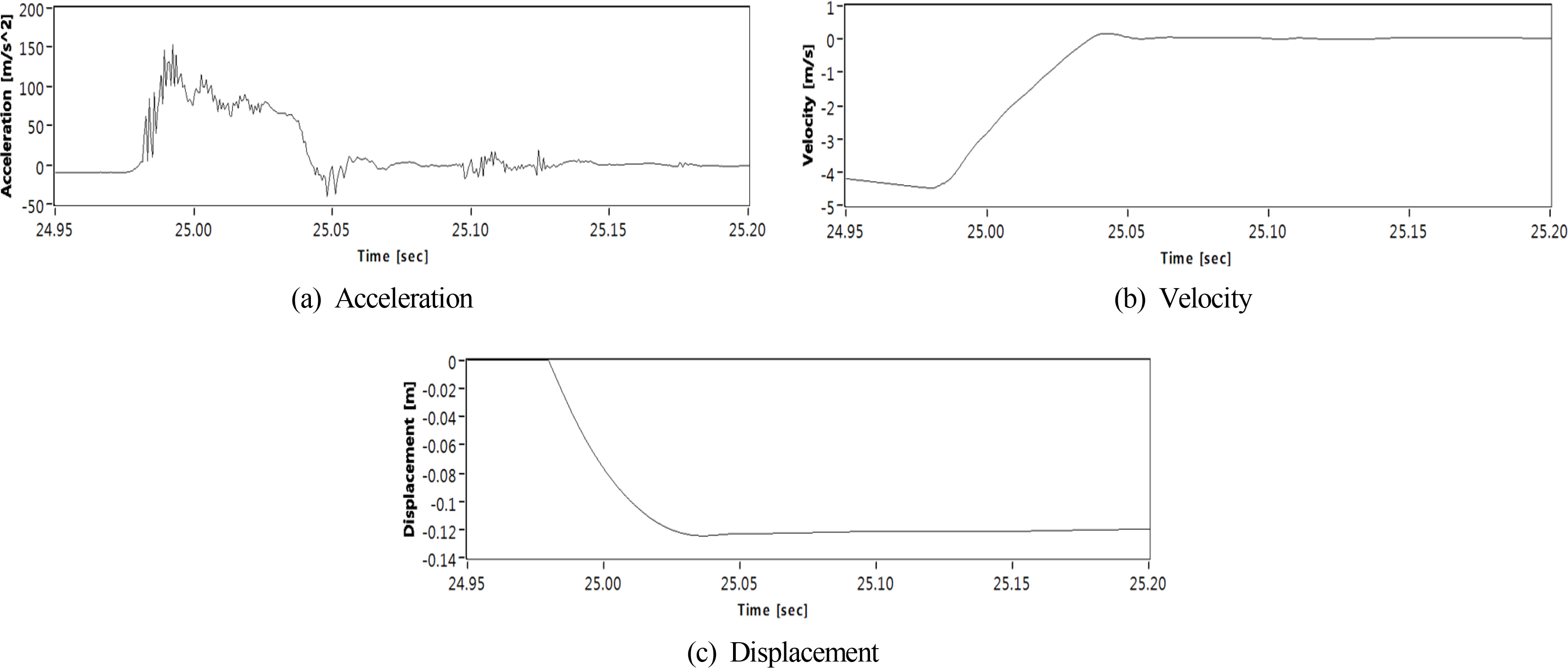
Estimated results using selected acceleration
As shown in Table 1, measurements were performed at the falling heights of 1, 3, and 6 m and the results were compared with the estimated penetration depths. When the FFCPT was fell from a height of 6 m or higher, over-ranged acceleration signals were continuously captured. This was due to the landfill, which consisted of sandy soil from the surface to a depth of approximately 0.3 m and gravel below a depth of 0.3 m. When the FFCPT was fallen from a 6 m height, the maximum measured penetration depth was 0.275 m, and hence fall experiments could not be performed at higher heights. Effective values could be obtained because the ground penetration slope during the fall experiment was within the range of ± 5°. The error of the penetration depth estimated through this experiment relative to the measurement was 2.9% on average.
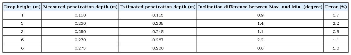
Comparison of penetration depth results
5. Conclusion
The estimated penetration depth of the FFCPT under development to determine the geotechnical properties of the seabed was examined. The developed device estimated the penetration depth by integrating acceleration signals. It was experimentally verified that the acceleration signals generated when the FFCPT hits the ground show the pattern of 5 phases: impact, penetration, initial finish, reaction, and final finish. Repeated fall ing tests were performed at different falling heights in the land experiment. The measured values and estimated values of the penetration depth were compared in this experiment, and the error of the estimated penetration depth relative to the measurement was 2.9% on average.

Acknowledgements
This study was supported by research grants from Korea Institute of Ocean Science and Technology(PE99832).