Study on the Vibration Characteristics of Yaw Gear System for Large-Capacity Offshore Wind Turbine
Article information

Abstract
Vibration and noise must be considered to maximize the efficiency of a yaw system and reduce the fatigue load acting on a wind turbine. This study investigated a method for analyzing yaw-system vibration based on the change in the load-duration distribution (LDD). A substructure synthesis method was combined with a planetary gear train rotational vibration model and finite element models of the housing and carriers. For the vibration excitation sources, the mass imbalance, gear mesh frequency, and bearing defect frequency were considered, and a critical speed analysis was performed. The analysis results showed that the critical speed did not occur within the operating speed range, but a defect occurred in the bearing of the first-stage planetary gear system. It was found that the bearing stiffness and first natural frequency increased with the LDD load. In addition, no vibration occurred in the operating speed range under any of the LDD loads. Because the rolling bearing stiffness changed with the LDD, it was necessary to consider the LDD when analyzing the wind turbine vibration.
1. Introduction
A wind turbine typically consists of a blade rotor that transfers the received energy to a generator, a power transfer unit, a nacelle in which the generator and various electrical and mechanical devices are installed, and a tower that supports the weight of the nacelle assembly and load delivered through the blade (Hong et al., 2006). Because even a single malfunction of a wind-power generation system can induce significant economic and social losses, only products that can guarantee at least 20 years of service life can enter the commercial market. In addition to the increase in the size of the system, consideration must be given to vibration, noise, and weight reduction when designing a gearbox because a service life of at least 20 years must be guaranteed (Lee and Kang, 2014).
A yaw system maximizes the system efficiency and reduces the fatigue load acting on a wind turbine by positioning the rotor and nacelle so that they face in the direction that the wind is blowing. The vibration and noise of the yaw system must be taken into account because a wind turbine must be guaranteed a service life of at least 20 years. Accordingly, continuous research has been conducted on the vibration and noise of rotary machines. Itoh studied a method of using a damped free vibration mode shape for systems with complex structures (Itoh, 1973). Kahraman et al. (1992) calculated the critical speed considering the torsion of a gear and coupled effects of bending vibration, and found the response for an unbalanced mass and transmission error using a finite element method. To analyze the response of a planetary gear train using the finite element method, Parker et al. (2000) designed a finite element model of a planetary gear train and analyzed the dynamic response and unique characteristics such as the natural frequency and vibration modes. Dong et al. (2015) researched non-linear dynamic modeling, including torsion modeling, in order to examine the vibration characteristics of a planetary gear. Wang and Morse (1972) performed static and dynamic torsion response analyses of a general gear train system using a transfer matrix method. Choy et al. (1991) analyzed the steady state response by developing a three-stage spur gear system model that included the torsion of a gear train. To improve the analysis techniques for complex planetary gear systems considering various types of frictions, Tanaka analyzed the characteristics of a planetary gear in the form of a matrix by finding system equations from element equations, corresponding to the finite element method (FEM) (Tanaka, 1984). Iida et al. (1980) claimed that a gear train model yielded different results depending on whether the dynamic coupling of a spur gear was considered. Bossanyi studied a method for controlling the torque applied to the yaw to balance the energy according to the load and for individually controlling the yaw system to reduce loads applied asymmetrically (Bossanyi, 2005). Prohl proposed a transfer matrix model of a gear train, and analyzed the critical speed, dynamic response, and unique characteristics of this gear train supported by a bearing based on the transfer matrix method (Prohl, 1945).
The aforementioned studies performed vibration analyses only for a gear train without considering the finite element models of the housing and carriers. Therefore, there is a need for a vibration analysis that considers a finite element model of the housing and gear, as well as the planetary gear train.
This study examined the vibration characteristics of the yaw system for a large-capacity wind turbine, and proposed a method for performing a vibration analysis of the yaw system by combining finite element models of the housing and carriers with a rotor vibration model of the planetary gear train using a substructure synthesis method. Furthermore, the characteristics were analyzed by comparing the natural frequency results with and without consideration given to the finite elements of the housing and carriers. The vibration excitation sources for the bearing defect error, gear mesh frequency, and mass imbalance acting on the yaw system were modeled, and the critical speed was analyzed to determine the resonance within the scope of the operation speed range.
2. Vibration Modeling and Vibration Characteristic Analysis of the Yaw System
2.1 Vibration Modeling of the Yaw System
In this study, modeling was performed using an 8-MW yaw decelerator model. The vibration model of the yaw system was designed using MASTA 12.1, which is a gear analysis program. Fig. 1 shows the vibration model of the yaw system, which consisted of a four-stage planetary gear system. The output axis of each stage, when a ring gear was fixed, was connected to the subsequent input axis through a spline. The power of a motor input through the first sun gear was delivered to the output axis through the second, third, and fourth planetary gear systems.
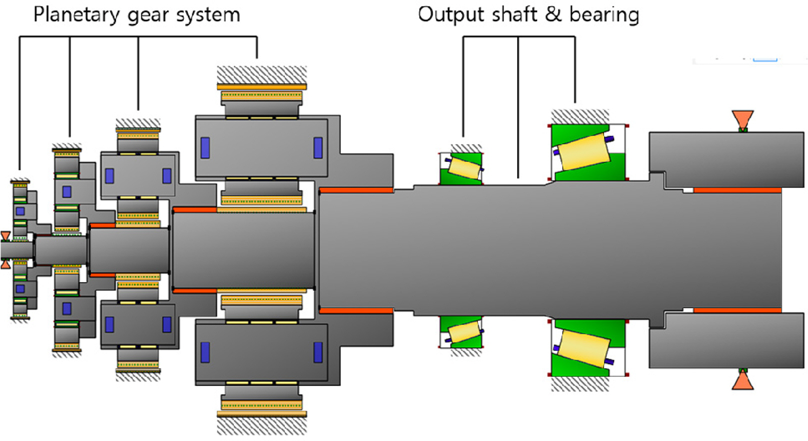
Two-dimensional vibration model of yaw gear system
Detailed specifications of the four stages of the planetary gear system are presented in Tables 1, 2, 3, and 4, respectively. The reduction ratios of the planetary gear system were 7.714 in stage 1, 6.706 in stage 2, 4.952 in stage 3, and 0.95 in stage 4; the overall reduction ratio was approximately 1,219.96, with the 1,158.961 rpm rotational speed of the motor input in the first sun gear decelerated to 0.47 rpm.
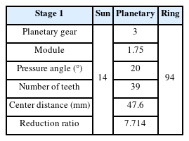
Planetary information for 1st stage of yaw gear system
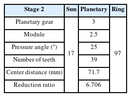
Planetary information for 2nd stage of yaw gear system
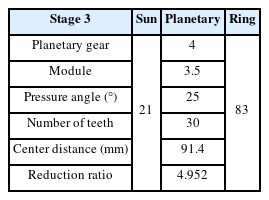
Planetary information for 3rd stage of yaw gear system

Planetary information for 4th stage of yaw gear system
2.2 Vibration Characteristic Analysis of the Yaw System
Most structural analyses are performed based on the finite element method, but an extensive amount of time is required for computing and dividing the mesh for large structures. To overcome this drawback, the entire structure was divided into several elements, and then each modal variable was independently determined for each element. The elements were then synthesized using geometric suitability conditions for the elements as constraint conditions as part of the substructure synthesis method to find the modal variable, stress, and strain of the structure (Choi et al., 1989).
MASTA 12.1 was used for the rotor-vibration modeling of the yaw system gear train, and then the ANSYS 22 finite element models of the housing and carriers were connected through the substructure synthesis method. Fig. 2 shows the finite element model of the housing that was produced using ANSYS 22. Because the teeth of the ring gear were included in the MASTA 12.1 vibration model, they were excluded from the finite element model. If the mesh quality of a finite element model is poor when synthesizing it with the gear train model using MASTA 12.1, a matrix cannot be formed and an error occurs. Accordingly, the bolt holes of the ring gear, flange, and output housing were deleted when forming the mesh in order to improve the mesh quality. The finite element model consisted of 191,948 nodes and 744,424 elements.

Finite element model of housing
Fig. 3 shows the part where the gear train and housing node are connected. The output axis bearing of the gear train is in contact with the output housing, and the ring gear of each stage is connected with the ring gear of the housing.
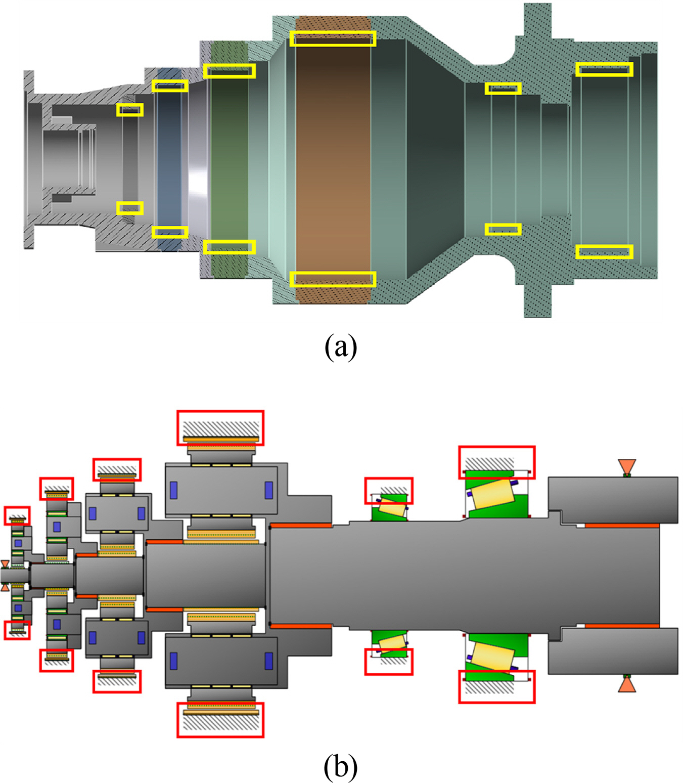
Housing and gear train connection parts: (a) housing connection part and (b) gear train connection part
Fig. 4 shows the finite element models of the carriers devised to be synthesized with the gear train model. The finite element model of the first carrier has 82,866 nodes and 23,228 elements, that of the second carrier has 253,896 nodes and 69,742 elements, that of the third carrier has 159,828 nodes and 46,432 elements, and that of the fourth carrier has 597,403 nodes and 163,068 elements.
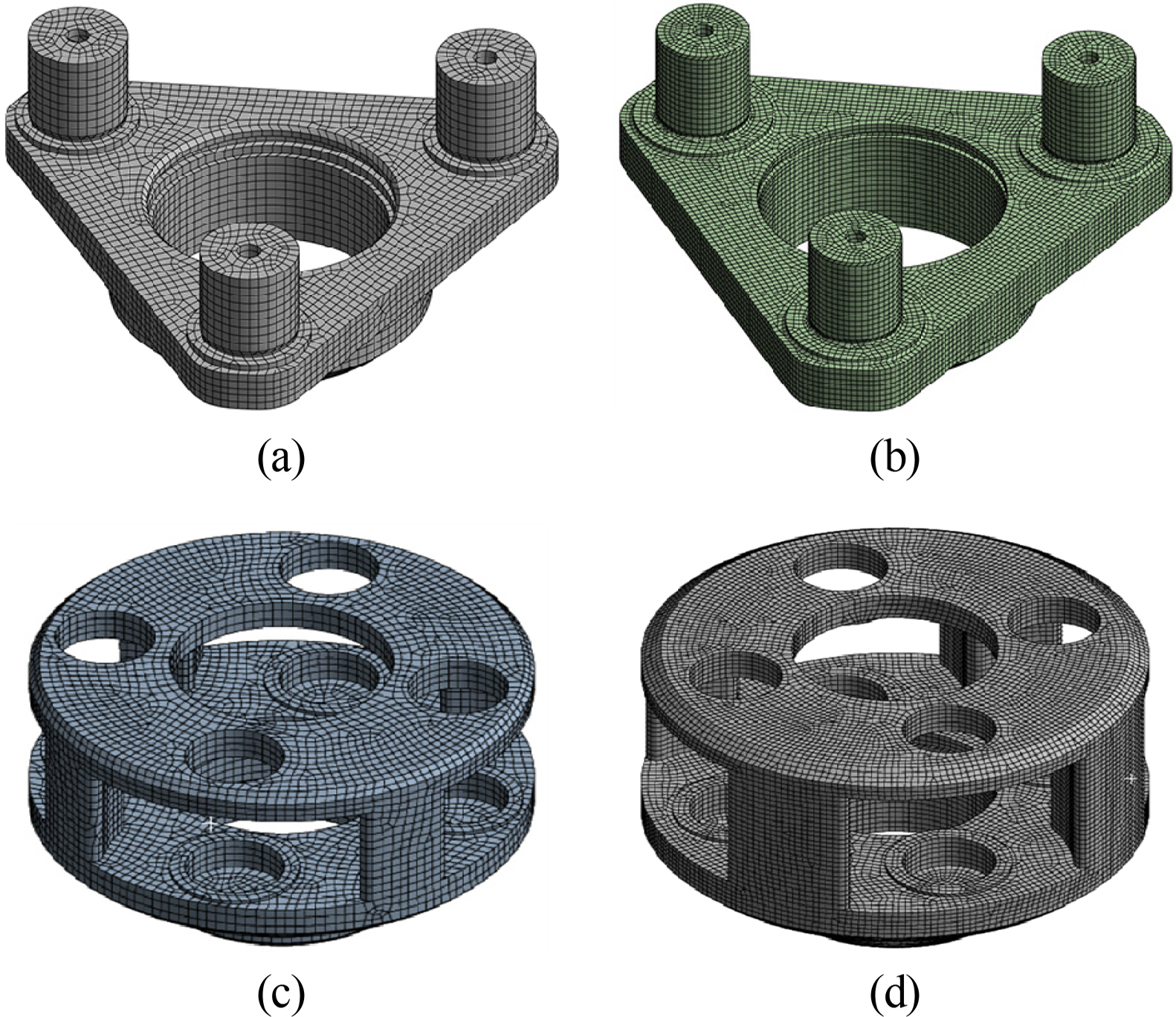
Carrier finite element models: (a) 1st carrier, (b) 2nd carrier, (c) 3rd carrier, and (d) 4th carrier
Fig. 5 shows the part where the gear train and carriers are connected. The substructure synthesis of the carriers involves connecting each carrier with the node of the part contacting the planetary pin, and connecting the node of the spline at which the carrier is connected to the subsequent stage.

Carrier and gear-train connection parts: (a) gear train, (b) 1st carrier, (c) 2nd carrier, (d) 3rd carrier, and (e) 4th carrier
Fig. 6(a) shows the vibration model when only the gear train is considered, without considering the finite element models of the housing and carriers. Fig. 6(b) shows the vibration model when the finite element models of the housing and carriers are synthesized with the planetary gear train using the substructure synthesis method. Table 5 presents a comparison of the natural frequencies in cases where the finite element models of the housing and carriers were and were not taken into consideration, under the condition that the torque was the largest among the load duration distribution (LDD) data. The natural frequency of the case where the finite element models of the housing and carriers were taken into consideration was lower than that where they were not taken into consideration.
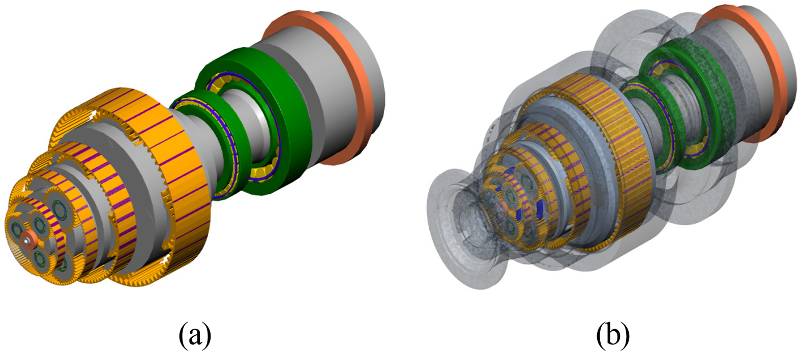
Natural frequency comparison models: (a) vibration model without finite element mode and (b) vibration modeling with infinite element mode
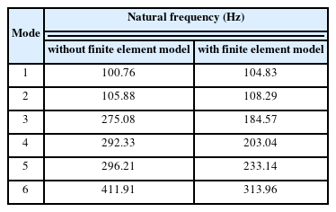
Comparison of natural frequency analysis results
3. Vibration Excitation Source Modeling and Critical Speed Analysis of the Yaw System
3.1 Modeling of the Vibration Excitation Source
The excitation sources applied to the yaw system included the mass imbalance, gear mesh frequency, and errors in the bearing installation. The gear mesh frequency is primarily caused by gear-teeth machining errors and system deformation due to loads, and is expressed as the product of the rotational speed and number of gear teeth. Mass imbalance occurs when there is an eccentric mass caused by machining errors, and is identical to the rotational speed. The types of excitation frequencies due to rolling-bearing defects include the fundamental train frequency (FTF), ball spin frequency (BS), outer racer frequency (OR), and inner racer frequency (IR) (Lee, 1999).
Table 6 presents the bearing characteristics of each stage, while Table 7 presents the excitation frequency ratio considering the mass imbalance and gear mesh frequency of the yaw system. Here, 1X indicates the changes in the rotational speed input in the first sun gear. The excitation sources related to bearing defects are listed in Table 8.
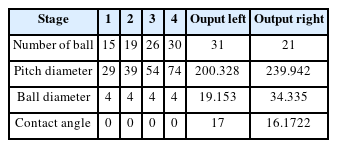
Rolling bearing information
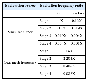
Excitation frequency of mass imbalance and gear mesh frequency

Excitation frequency ratio of bearing
3.2 Critical Speed Analysis
Vibration and noise occur in the yaw system of a wind turbine when the excitation frequency and natural frequency of the yaw system are identical. If the excitation frequency is γi, where i = 1, 2, 3, ⋯,N, and the natural frequency of the yaw system is λi, where i = 1, 2, 3, ⋯, N, resonance occurs when γi = λi . If the excitation frequency is γi = ci ωcr, critical speed ωcr becomes ωcr = λi/ci . Here, ci is the coefficient of the excitation frequency (Kim et al., 2011).
The input speed of the yaw system was 1,158.96 rpm; Tables 6 and 8 present the excitation sources with respect to changes in the input speed. Figs. 7 and 8 show Campbell diagrams of the mass imbalance, gear mesh frequency, and bearing defects (FTF, BS, OR, IR).
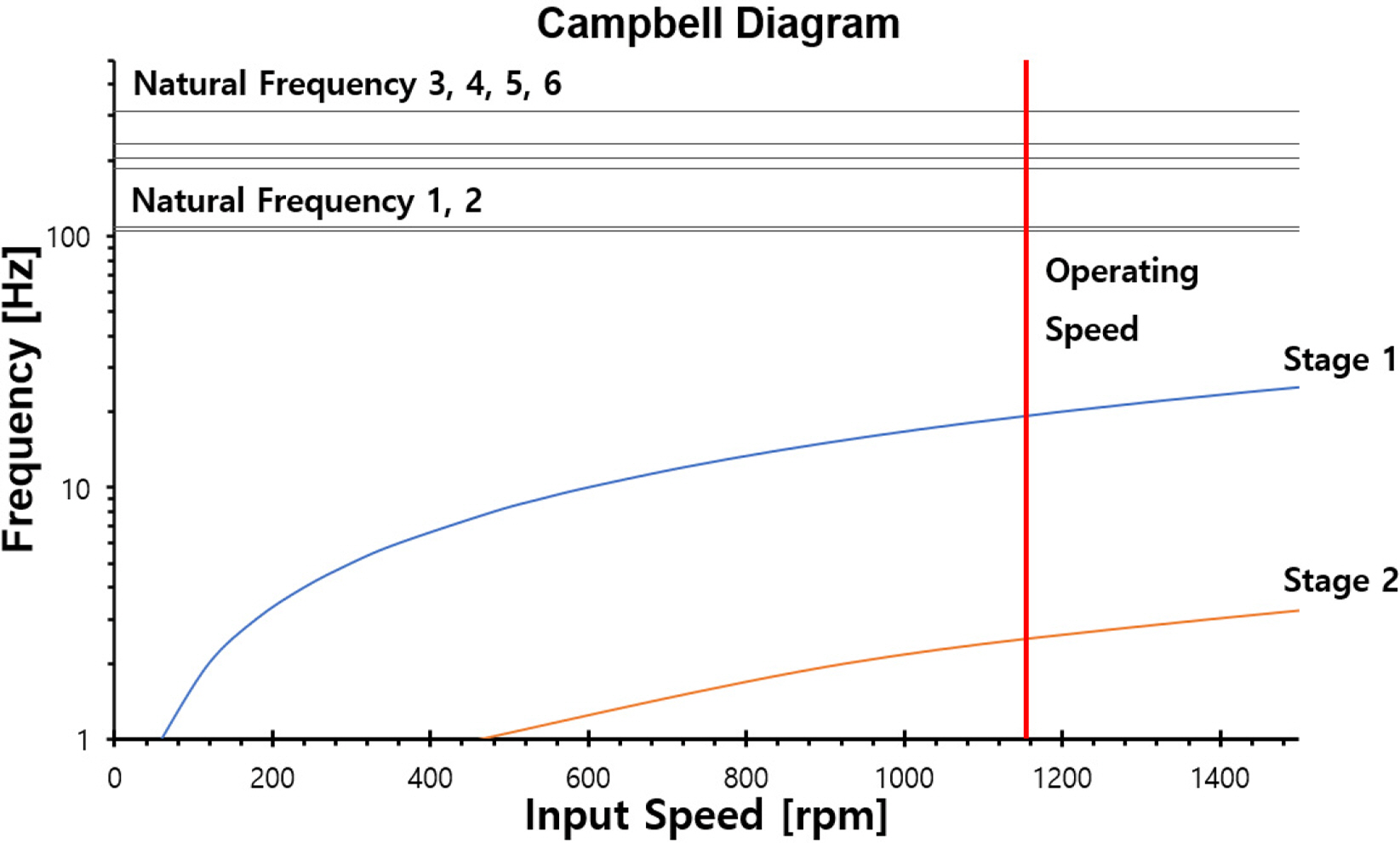
Campbell diagram of mass unbalance

Campbell diagram of gear mesh frequency
Figs. 7‒14 show that the critical speed of the mass imbalance, gear mesh frequency, and bearing defects did not occur within the operation speed (1,158.96 rpm) range.
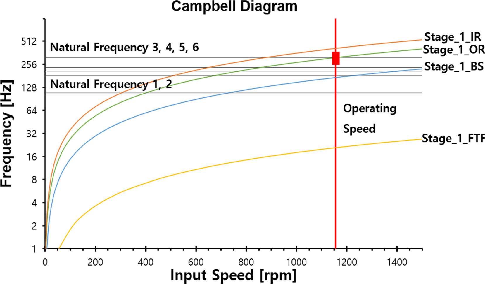
Campbell diagram of stage 1 bearing
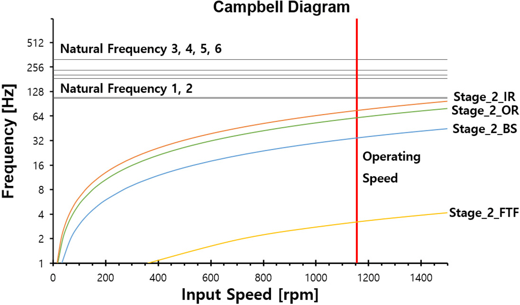
Campbell diagram of stage 2 bearing
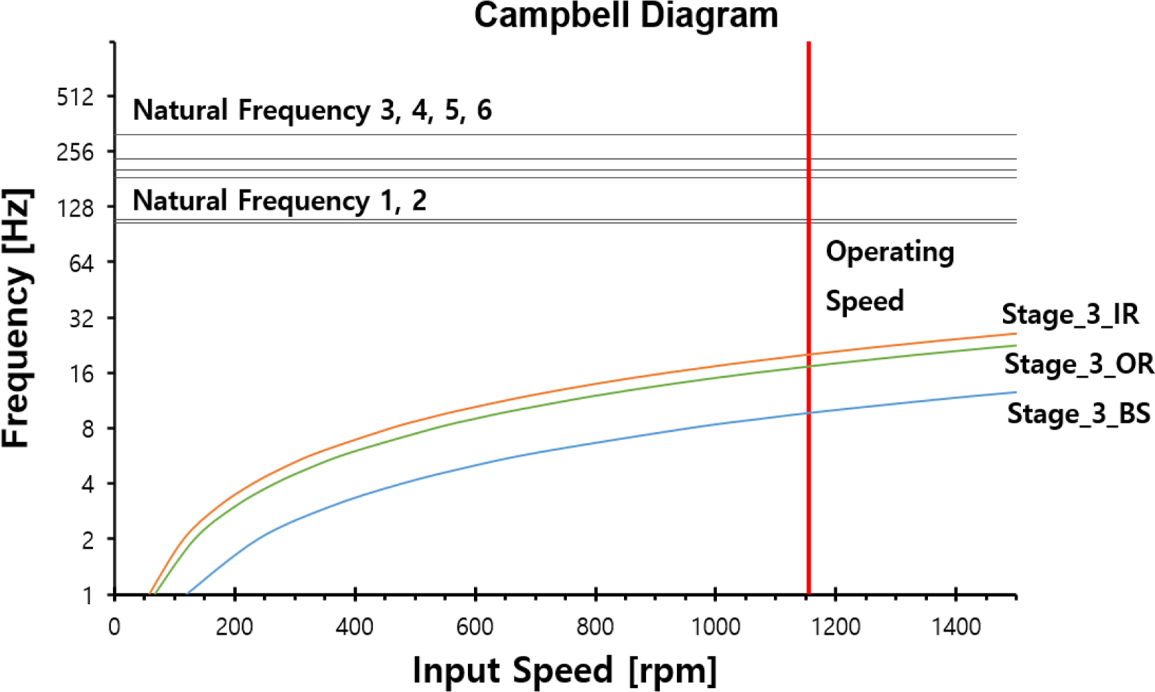
Campbell diagram of stage 3 bearing

Campbell diagram of stage 4 bearing
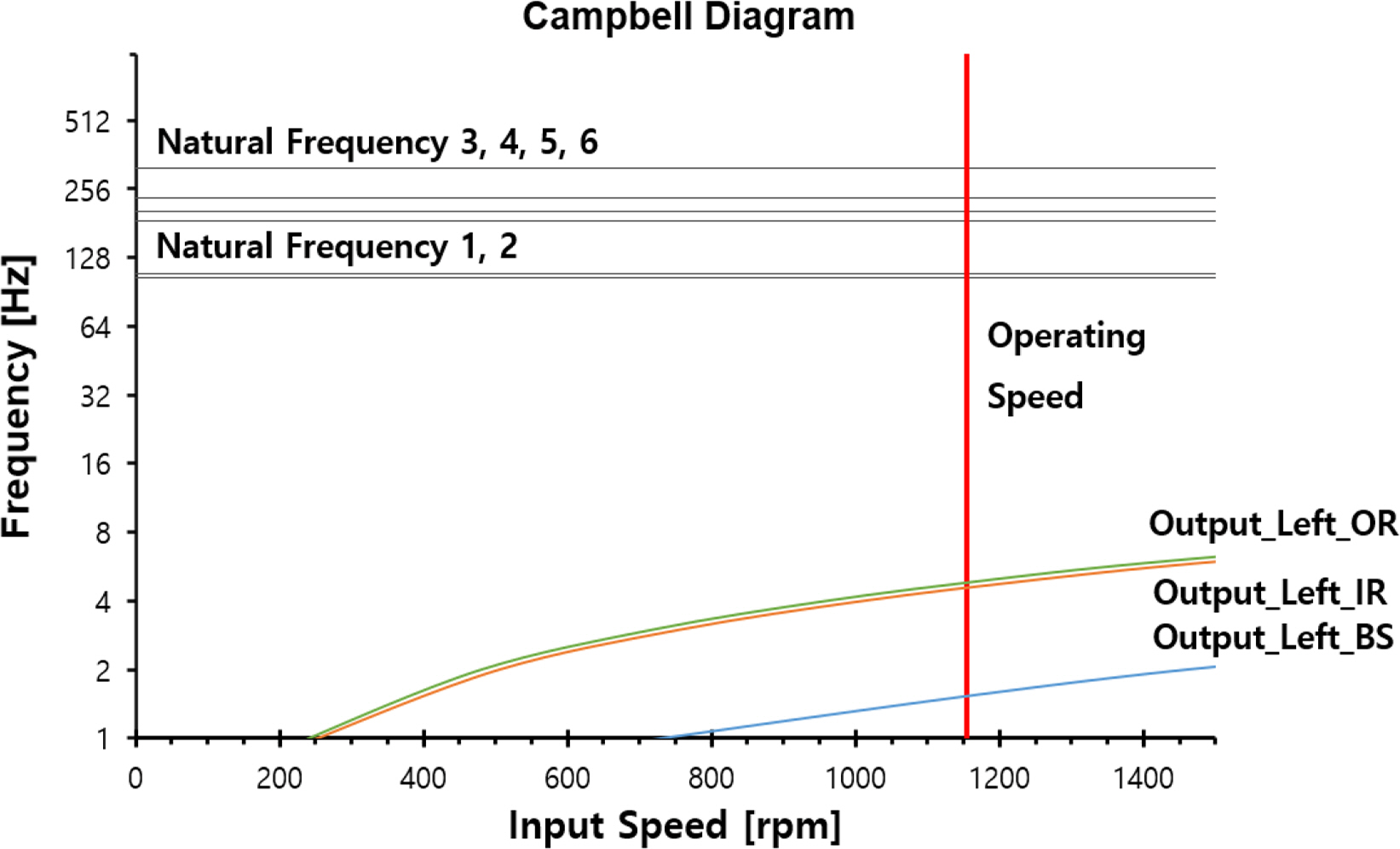
Campbell diagram of output left bearing
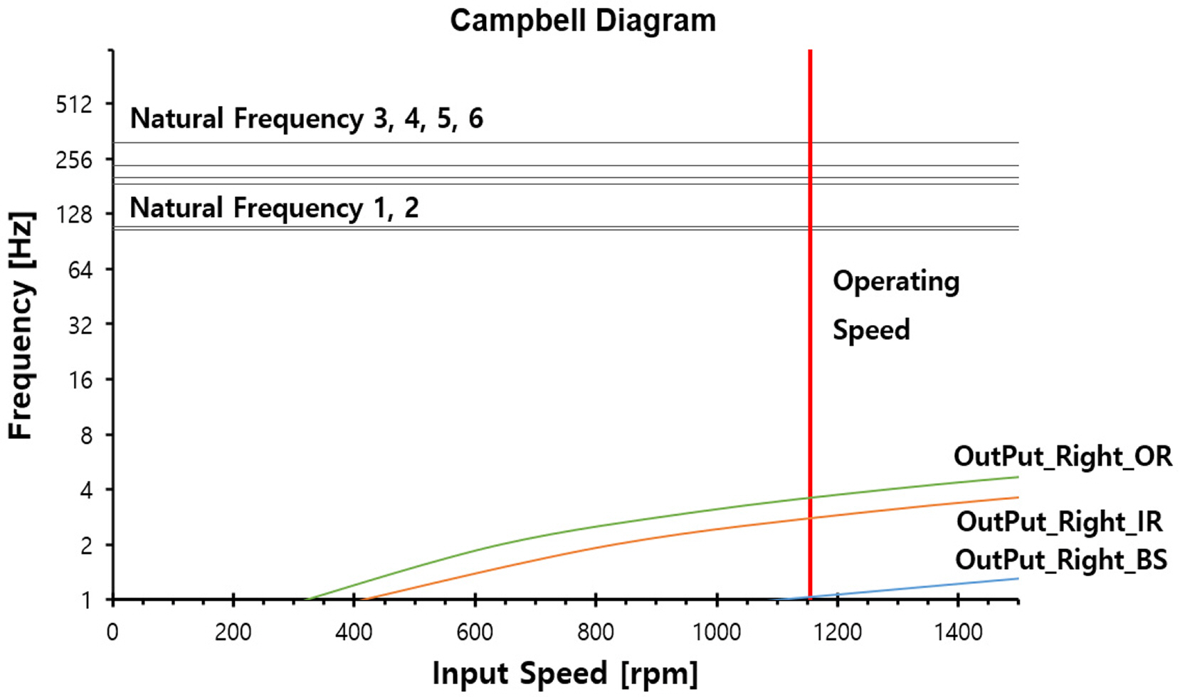
Campbell diagram of output right bearing
Fig. 9 presents the Campbell diagram of the stage 1 planetary gear, where the bearing outer ring of the first planetary gear coincides with the natural frequency of mode 6, as listed in Table 6; the mode shape of the sixth natural frequency is illustrated in Fig. 15. According to the mode shape results, a large vibration mode occurred in the vertical direction of the first planetary gear, which indicated that the bearing condition of the first planetary gear requires regular inspections.
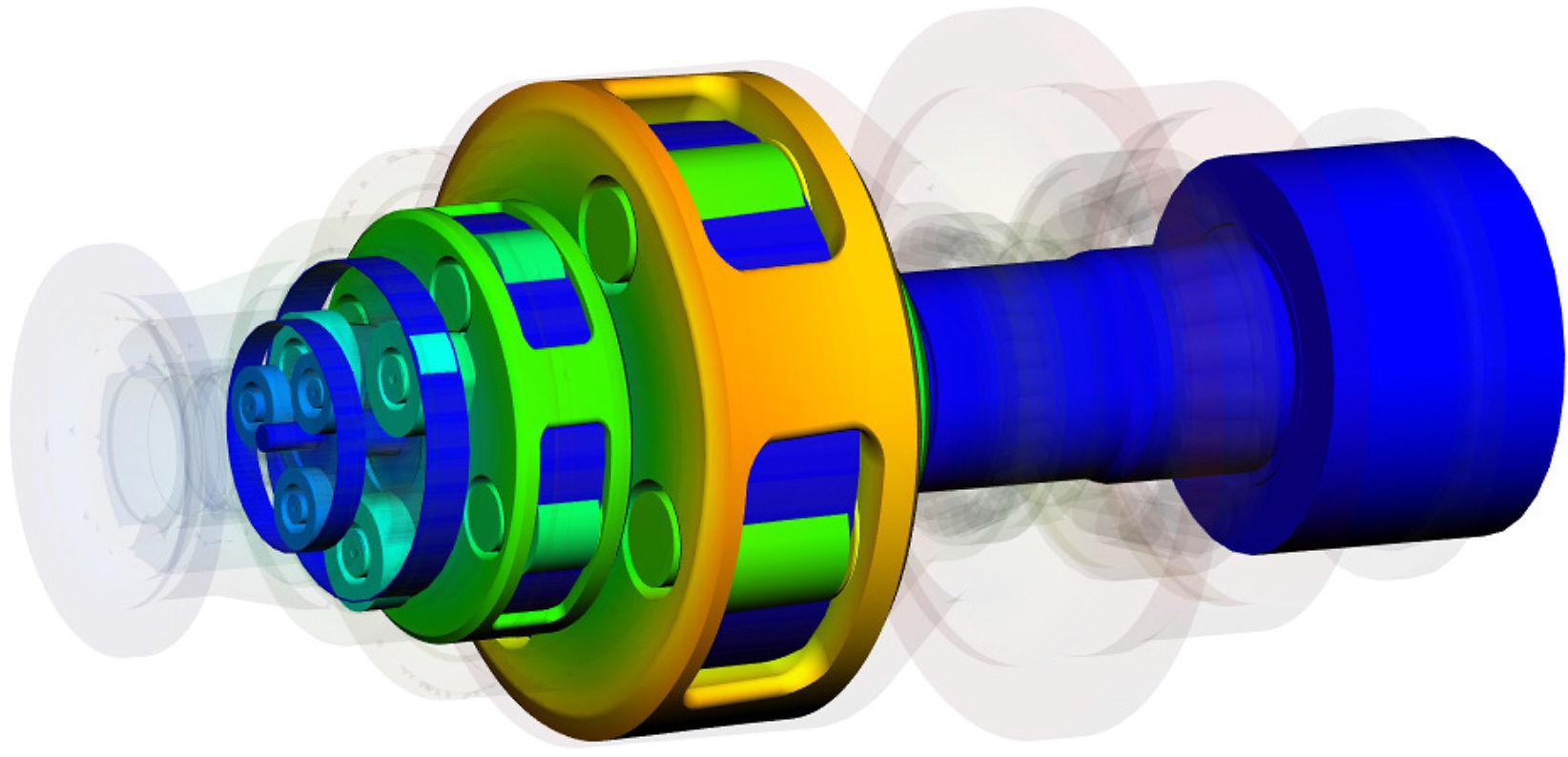
Mode shape of mode 6
4. Natural Frequency Characteristic Analysis with Respect to Changes in the LDD
The mathematical model of the vibration system of a wind turbine yaw system can be expressed as shown in Eq. (1).
Here, [M] is the system mass matrix, [C] is the system damping matrix, [K] is the system stiffness matrix, and q is the system response (Min et al., 2015).
Eq. (2) expresses the torsion, rotational, and bending direction vectors, along with the three displacement vectors of x, y, and z.
A general industrial gear box receives a fairly constant load. The vibration analysis of a wind turbine must consider various types of LDDs. The rolling bearing stiffness of a wind turbine gear box varies depending on the applied torque; thus, further research is needed on the effects of changes in the LDD on the first natural frequency.
Because there is a lack of research on the changes in the characteristics of the natural frequency with respect to changes in the LDD, this system found the natural frequency of the yaw system in terms of changes in the LDD.
Figs. 16 and 17 illustrate the changes in the natural frequency with respect to the bearing stiffness when the largest load (116,320 Nm) of the LDD was considered to be one, and the load was increased in 10% increments from 10% of the largest load to 100%.
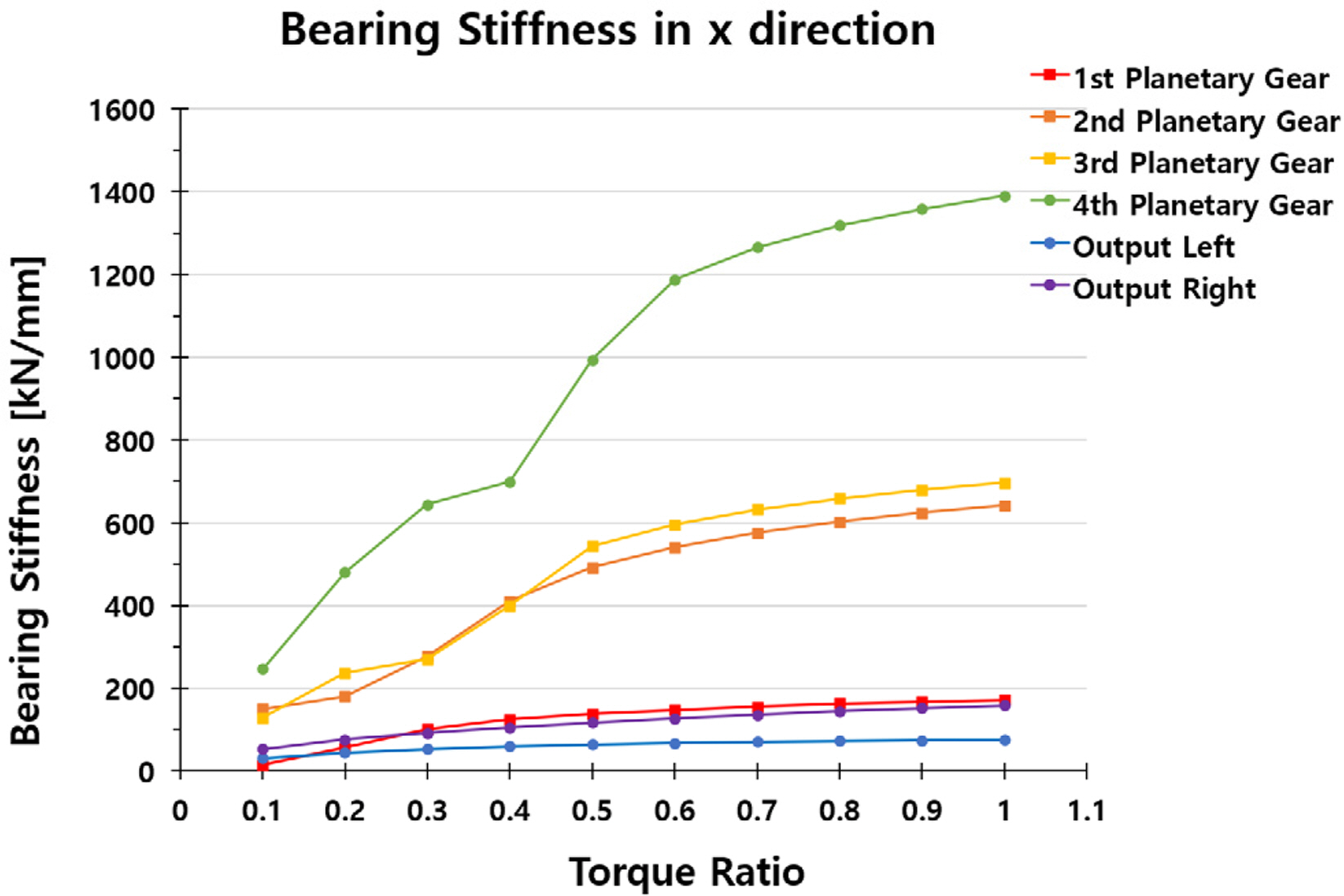
Variation of bearing stiffness in x-direction according to load

Variation of bearing stiffness in y-direction according to load
Fig. 16 shows the stiffness variation in the x-direction of a bearing in each stage according to changes in the load. The stiffness in the x-direction varied significantly with respect to the load.
Fig. 17 shows the stiffness variation in the y-direction of a bearing in each stage according to changes in the load. The stiffness in the y-direction also varied significantly with respect to the load. The detailed numerical values shown in Figs. 16 and 17 are presented in Table 9 and Table 10, respectively.
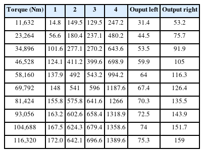
Changes in x-direction bearing stiffness according to load
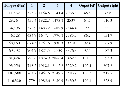
Changes in y-direction bearing stiffness according to load
Fig. 18 shows the variations in the first natural frequency with respect to the load. Because the lowest first natural frequency was 72.186 Hz, exceeding the operation speed of 1,158.96 rpm (19.316 Hz), all the LDD data were safely within the range of the operation speed. The detailed numerical values shown in Fig. 18 are presented in Table 11.
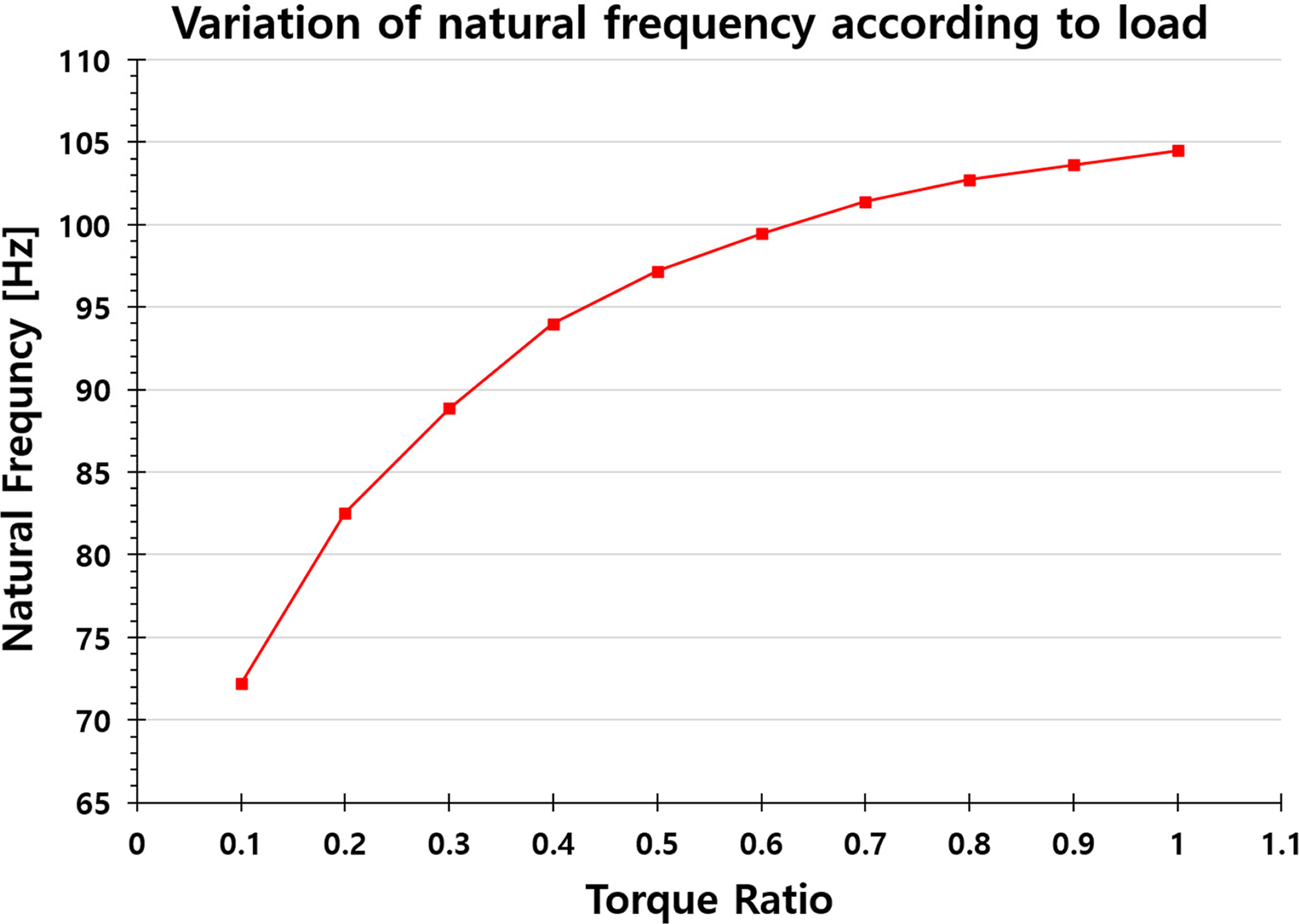
Variation of natural frequency according to load

Changes in natural frequency according to load
5. Conclusion
This study investigated a method for combining finite element models of the housing and carriers with the rotor vibration model of a planetary gear train through substructure synthesis and analyzing the vibration of the yaw system with respect to variations in the LDD.
When the natural frequencies were compared for cases where the finite elements of the housing and carriers were and were not considered, the natural frequency was lower in the case where the finite element models were taken into consideration. In addition, the critical speed of the yaw system was analyzed by modeling the vibration excitation sources for the mass imbalance, gear mesh frequency, and bearing defect frequency applied to the yaw system, and the results demonstrated that the critical speed of the mass imbalance and gear mesh frequency did not occur within the operation-speed range. However, the bearing condition must be inspected periodically because the outer ring of the first planetary gear bearing coincided with the sixth natural frequency (313.96 Hz) in the critical speed analysis of the bearing installation error.
When the LDD was increased in 10% increments from 10% of the largest load to 100%, both the bearing stiffness and first natural frequency increased with the LDD. Furthermore, the first natural frequency was 72.186 Hz for the lowest LDD, which exceeded the operation speed of 1,158.96 rpm (19.316 Hz); thus, according to the changes in the LDD, the vibration did not occur within the operation-speed range. Because the rolling bearing stiffness varied with the LDD, further analysis of the vibration of a wind turbine must be performed while considering the LDD.
Notes
Seok-Hwan Ahn serves as an editorial board member of the Journal of Ocean Engineering and Technology, but he had no role in the decision to publish this article. No potential conflict of interest relevant to this article was reported.
This thesis is research of a study conducted with the support of the ‘Renewable Energy Core Technology Development Project’ supported by the Korea Energy Technology Evaluation and Planning. (No. 20213030020020)