Tracking of ARPA Radar Signals Based on UK–PDAF and Fusion with AIS Data
Article information
Abstract
To maintain the existing systems of ships and introduce autonomous operation technology, it is necessary to improve situational awareness through the sensor fusion of the automatic identification system (AIS) and automatic radar plotting aid (ARPA), which are installed sensors. This study proposes an algorithm for determining whether AIS and ARPA signals are sent to the same ship in real time. To minimize the number of errors caused by the time series and abnormal phenomena of heterogeneous signals, a tracking method based on the combination of the unscented Kalman filter and probabilistic data association filter is performed on ARPA radar signals, and a position prediction method is applied to AIS signals. Especially, the proposed algorithm determines whether the signal is for the same vessel by comparing motion-related components among data of heterogeneous signals to which the corresponding method is applied. Finally, a measurement test is conducted on a training ship. In this process, the proposed algorithm is validated using the AIS and ARPA signal data received by the voyage data recorder for the same ship. In addition, the proposed algorithm is verified by comparing the test results with those obtained from raw data. Therefore, it is recommended to use a sensor fusion algorithm that considers the characteristics of sensors to improve the situational awareness accuracy of existing ship systems.
1. Introduction
Ship collision is a major marine accident that incurs severe economic loss and causes death and environmental pollution. Although ships are equipped with cutting-edge technological devices, e.g., electric chart display and information system, automatic radar plotting aid (ARPA), automatic identification system (AIS), and integrated navigation system (INS), several studies on marine accidents confirmed that more than 80% of marine accidents are related to human factors (Hu et al., 2020). Thus, studies related to autonomous vessels have been conducted to eliminate human factors that cause marine accidents. The International Maritime Organization categorizes the level of autonomy of a maritime autonomous surface ship into four stages. A ship with automated processes and decision-making support is classified as Level 1, a ship with remote control and the ability to board sailors is classified as Level 2, a ship with remote control but no sailors is classified as Level 3, and a ship with complete autonomy and decision-making capabilities is classified as Level 4. With the ongoing development of information and communications technology, studies have been conducted on vessels that independently recognize circumstances, avoid collisions, and plan routes to satisfy a high level of autonomy.
Autonomous vessels avoid collision based on the following four steps: detection and circumstantial recognition, decision-making, route planning, and control (Woo, 2018). During the detection and circumstantial recognition stage, obstacles are detected, and circumstances are determined using heterogenous sensors installed in the ship. During the decision-making stage, the collision risk is determined for the operating vessel. During the route planning stage, the evasion steering of the ship is ascertained based on the risk of collision, and the target route is decided accordingly. Finally, the control stage includes the regulation of the steering gear and propeller for mobility that is required for sailing along the target route. Thus, a high level of accuracy is essential for the initial detection and circumstantial recognition stage to establish a safe autonomous navigation system, and the demand for the sensor fusion technique has been increasing accordingly.
With regard to sensor fusion related to ships, Kim et al. (2014) studied the vessel information fusion algorithm using the blackboard system that can manifoldly consider various types of information based on AIS and ARPA signals. However, uncertainties such as the global positioning system (GPS) location error (i.e., situations where GPS signals cannot be received), discord in AIS data update time, and instability in radar data were not considered. Habtemariam et al. (2015) studied the fusion algorithm of the measurement level that combines the AIS and radar signals based on the joint probabilistic data association (JPDA) framework and performed simulations based on the Monte Carlo Runs. In the corresponding study, they developed a fusion track to initialize based on the radar measurements, allocated the ID list of AIS signals based on the initial distribution, and proposed an algorithm that provides updated information based on AIS or radar data according to the presence of the AIS signal. However, in real situations, time was not considered during the study; moreover, the study was performed for circumstances that include both signal data.
This study proposes a fusion algorithm of AIS and UK–PDAF-based ARPA radar signal tracking data that are applicable in actual environments for the real-time recognition of circumstances (Schreier, 2017). AIS data after reception is managed based on the maritime mobile service identity (MMSI) number, and a prediction method that was implemented based on the sailing information of the vessel within the AIS location payload is used to overcome the difficulties of combining abnormal phenomenon data. Moreover, after the reception of ARPA data, UKPDAF is used for tracking and predicting to manage units of tracks and prevent abnormal phenomena based on the ARPA data. The distance of the vessel traffic and motion variable obtained from the AIS and ARPA signals, respectively, are periodically compared to perform fusion between the two signals. Lastly, this research proceeded with measurement tests from vessels that actually navigate by boarding on a training ship of Korea Maritime & Ocean University to verify the validity of the proposed sensor fusion technique.
2. Tracking Method
2.1 Unscented Kalman Filter (UKF)
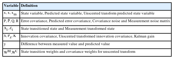
This study used a tracking algorithm based on the UKF to track objects (Labbe, 2014). Table 1 lists the prediction and update steps of the linear KF and UKF for better understanding. Eqs. (1)–(3) define the prediction steps of the linear KF and UKF, and Eqs. (4)–(10) define the update steps. The symbols listed in Table 1 are presented in Table 2.
2.2 Probabilistic Data Association Filter (PDAF)
In real situations, several measurement values exist for a single tracking round; Fig. 1 illustrates this situation. At time t, numerous measurement values (Track #2) can either exist for each round of tracking, or there may be a situation where no measurement value exists (Track #1). The KF uses a single measurement value for a single round of tracking; however, the PDAF is significantly different because it uses multiple measurement values for a single round of tracking.
In this study, the PDAF first determines the Mahalanobis distance, which represents the statistical distance between current measurements and the location of previously tracked objects. If this distance is smaller than the validation gate, the corresponding measurement value is used to update the UK–PDAF. Based on this process, the value that represents the extent of the contribution of the selected measurement value to the update of the tracking object was determined, followed by the new state estimation of the target object (hereafter target) using a combined innovation technique that corresponds to innovation covariance for updating the Kalman gain.
2.2.1 Measurement value validation
The validation step involves the process of selecting relevant values among kth measurements and using the selected values for state estimation. The range of validation used during the selection process is known as the validation gate, and the volume of the validation gate is defined as
Here, q denotes the dimension of the measurement value and γG denotes the threshold of the gate. S(k) represents the innovation covariance matrix, which is expressed in Eq. (12).
2.2.2 Data association
The estimation process would be more reliable if the state with the conditional mean of the measurement values within the validation gate mentioned in the measurement validation step is considered. Thus, a data association step is included (Eq. (13)).
In Eq. (13)Nv denotes the number of valid measurements, θi,k denotes the ith valid measurement at time k, and Zi,k denotes the incident observed from the actual target. Moreover, θ0,k denotes the incident where the valid measurements are obtained from a clutter (reflected signal that obstructs the target detection) instead of the target. Based on the aforementioned equation, it is assumed that only one measurement is derived from a single target. Therefore, θi,k (i = 0,1,…,Nv) are exclusive events, and the probability of θi,k, which is the combination of probability βi,k that the ith measurement will be derived from the actual target and probability β0,k that the measurement will be a clutter rather than an observation based on a real target, is defined in Eq. (14).
Here, PG denotes the probability that an accurate measurement exists within the validation gate and PD denotes the probability that an accurate value is observed using the radar sensor. Both values are determined using the sensor. The derived probability of relevance is used in determining the error covariance and UK–PDAF estimation values, and the corresponding process is expressed in Eq. (15).
Here,
This study develops a multi-tracking algorithm that can track (estimate) the state of the target (other ship) based on the ARPA radar measurement values obtained using the UK–PDAF-based tracking algorithm that combines the PDAF and UKF. Fig. 2 shows the flow chart of the corresponding algorithm.
3. Sensor Fusion
3.1 Location Prediction Technique Based on AIS Data
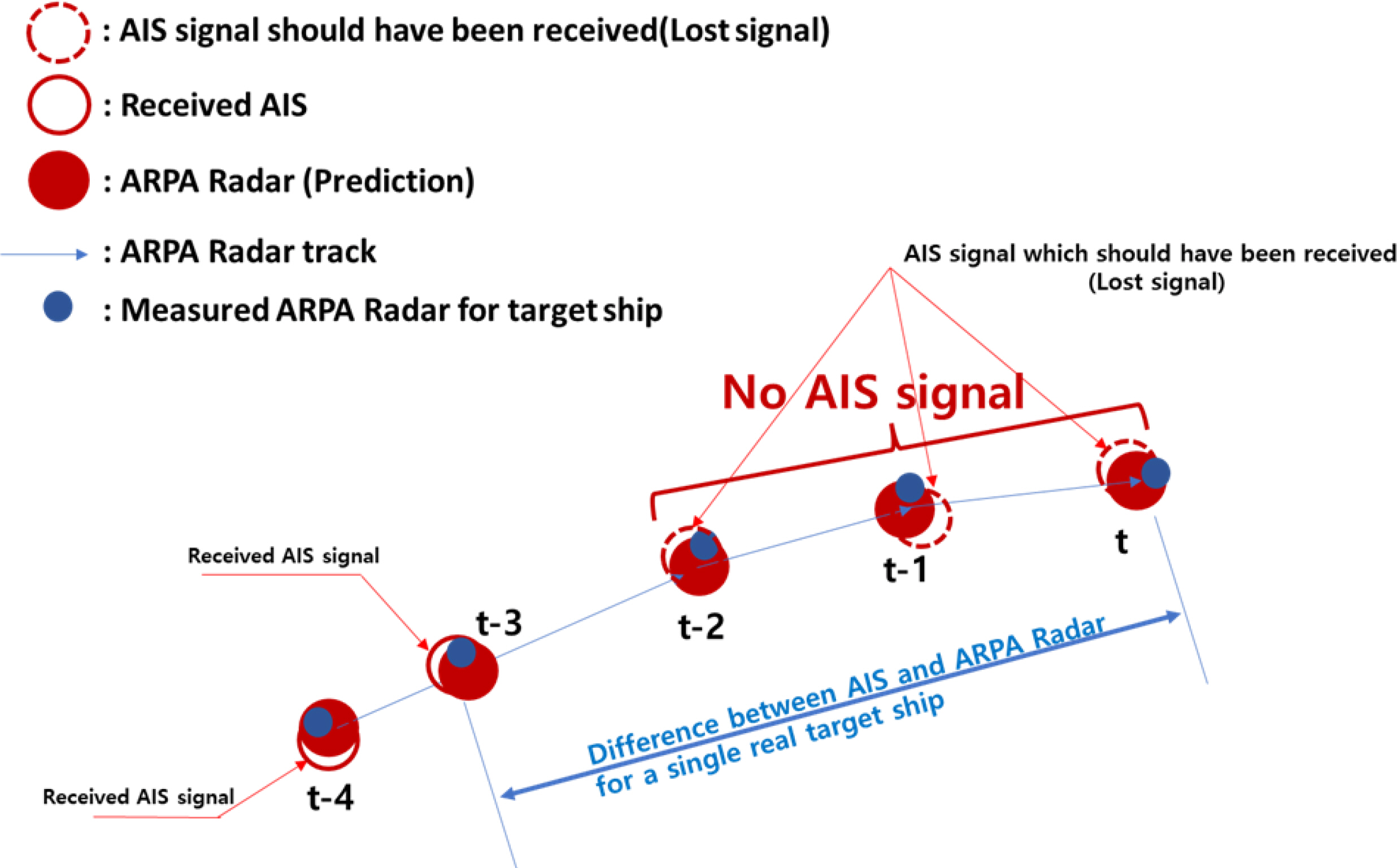
The data transfer period of AIS signals is determined based on the speed state of the vessel where the AIS system is installed, and refined data are transmitted according to the determined period. However, in reality, signals are missed owing to an increase in the load of the AIS communication channel and poor communication, from which the AIS signal period may become abnormal. Fig. 3 illustrates the aforementioned situation. As shown in Fig. 3, the red line circle represents the AIS signal received under normal circumstances, and the red dotted line circle presents the AIS signal that was not received owing to the aforementioned circumstances. The red-filled circle enclosed within a blue boundary shows the route generated from the ARPA and predicted signal through tracking. The blue-filled circle presents the actual measured signals of the ARPA radar. AIS and ARPA signals were received before step four (t-4) and step three (t-3) from the current time, within which two signals were fused. However, before step two (t-2), AIS signals were not received and updated, and only radar signals were received. Therefore, there was a significant difference between signals as time passed. This phenomenon exhibited a significant difference with regard to the track considering its location periodically updated and managed, which resulted in a loss in the combined relationship between the heterogenous signals (AIS and ARPA) for the same vessel.
To account for such uncertainty in the AIS signal, this study predicted the location of the AIS signal during sensor fusion to minimize the error caused by the long-term inability to receive the AIS signal. Moreover, the AIS signal was designed to possess a regular periodic effect identical to the ARPA signal for its use in the sensor fusion algorithm. The AIS-data-based location prediction method is defined in Eq. (16).
Here, ϕp and λp indicate the predicted latitude and longitude during sensor fusion, respectively. ϕA and λA indicate the latitude and longitude of the received AIS signal, respectively. v denotes the ground speed, θ denotes the course over the ground, δ denotes the angular distance, tS denotes the time of sensor fusion, and tA denotes the reception time of the corresponding AIS signal.
3.2 Sensor Fusion Algorithm
This section introduces the sensor fusion algorithm for determining whether two vessels are identical. Fig. 4 shows a flow chart of the sensor fusion algorithm. Moreover, the first to fourth steps of this algorithm are represented by Eqs. (17)–(20), and each step is performed with AIS signals based on each ARPA radar signal that exists during sensor fusion. There is a possibility that certain AIS signals overlap and combine with multiple ARPA signals because the corresponding process is performed based on the ARPA signals. Therefore, the ARPA signals underwent four steps, and the AIS signals added to the fusion candidate during the first step were used in the fifth step for verification. In this study, it was determined whether the heterogenous signals at 3-s intervals were associated with the same vessel based on the proposed sensor fusion algorithm, and the distinction process of step 1 was presented as the first fusion step.
During step 1 of sensor fusion, AIS signals that are within the threshold distance are selected based on the ARPA (Eq. (17)). In step 2, the AIS signals among the selected ones with the course over the ground within the threshold were selected (Eq. (18)). In step 3, the AIS signals among those that passed step 2 with the ground speed within the threshold were selected (Eq. (19)). Herein, the course over the ground represents the angle of the sailing direction of the vessel, and it is measured up to 360° clockwise based on the latitude of 0°. In step 4, if the number of AIS signals that passed step 3 was high, the AIS signals with the minimum distance were selected (Eq. (20)). The definitions of the symbols in Eqs. (17)–(20) are summarized in Table 3. In this study, in order to consider both the training ship which is as field-test site was not moving during measuring and the error according to the sensor performance, the threshold for the distance between the training ship and the traffic ship, course over the ground, and ground speed was limited to 200m, 20°, and 2 knot(1.09 m/s), respectively.
4. Validation
To validate the proposed sensor fusion algorithm, the sailing equipment of Hannara Ship as the training ship of Korea Maritime & Ocean University was used for the actual measurement of the surrounding vessels. Abnormal phenomena occurred during the actual measurement, and Table 4 lists the heterogenous signals of abnormal phenomena.
In Table 4, the second and third columns indicate the presence of abnormality and target number automatically assigned by the ARPA system, respectively. The fourth column lists the MMSI number as the criteria to be discerned for the vessel based on AIS reception signals.
4.1 Result and Abnormal Phenomenon of Case 1
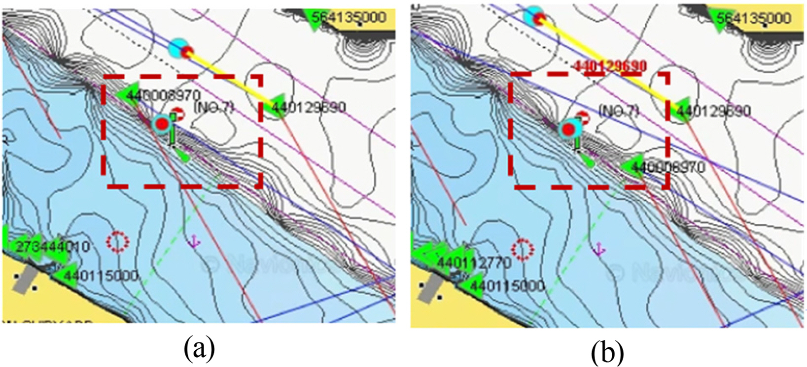
In Case 1, the AIS signal with MMSI number 440129690 was successfully fused with the ARPA signal with target number using the proposed method; however, an abnormal phenomenon occurred owing to the long-term non-reception of the AIS signal, which occurs owing to an increase in the AIS communication channel load, as described in Section 3.1. Fig. 5 shows the real-time measurements of this phenomenon. As shown in Fig. 5(a), the yellow line connects the green triangle (AIS signal) within circle A, and the red circle (ARPA signal) indicates that data were combined due to the fused AIS and ARPA signals. However, the radar signal location was updated, as shown in B of Fig. 5(b), after the end of the data update period (3-s update period of radar display). However, the AIS signal remained in location A of the circle without being received; Although it was the potential cause of failed sensor fusion, the AIS signal is connected to the ARPA signal as shown in Fig. 5(c), again.

Abnormal phenomenon in Case 1: (a) Initial state of associating each signal; (b) disassociated state after a certain time elapses; (c) reassociated state after more time elapses and AIS data are received
Fig. 6 shows the change according to the number of fusion trials with regard to the difference between the locations of the vessel obtained from the AIS and ARPA signals (ΔD =PositionAIS − PositionARPARadar) based on the analytical results of the phenomenon that occurred in Case 1. In the figure, the horizontal axis shows the number of fusion trials, and the vertical axis shows the difference in location. Moreover, the red dotted line presents the distance threshold mentioned in Section 3.2. Owing to abundant AIS data, some are indicated among the reception signals (Fig. 6) (within 500 m based on ARPA radar signal), and distinguishing the indicated symbols and colors becomes difficult. Therefore, the signals over than the red dotted line(200m threshold from the own ship) show that the locations of the traffic ships are at a far distance from the own ship(training ship). What each symbol has a parabola shape means that the traffic ship approached to the own ship in a certain duration and passed to far away.
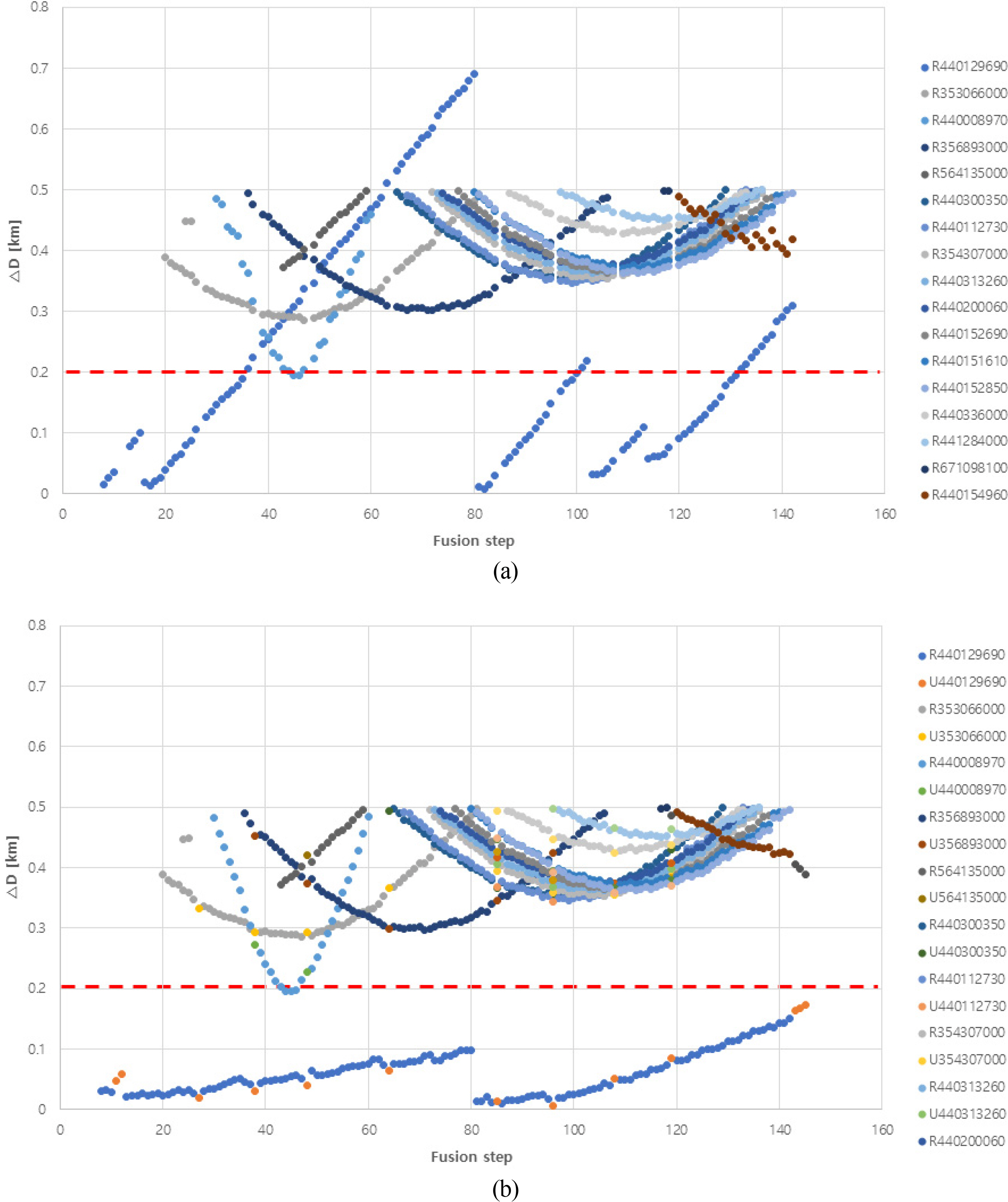
Relative distance in Case 1: (a) Relative distance based on the raw data; (b) Relative distance based on the processed data
Meanwhile, R440129690 (difference between the locations obtained based on Case 1 target 1 ARPA signal and the AIS signal with MMSI 440129690) in Fig. 6(a) shows that the fusion frequency increases with measurement time, and rapidly increases according to the long-term non-reception of the AIS signal. Fig. 6(b) shows that the aforementioned problem is resolved (R440129690, U440129690 of Fig. 6(b)) by updating the AIS signal using the proposed AIS-databased location prediction algorithm for the same situation.
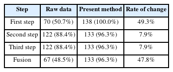
Table 5 lists the success rate of fusion with regard to the total number of attempts (138 times) for the aforementioned circumstance, and the application of the proposed method results in a higher success rate than that of the sensor fusion without additional processing.
4.2 Result and Abnormal Phenomenon of Case 2
In Case 2, fusion was successfully performed using the proposed method for the AIS signal with MMSI 440300740 and ARPA signal with target number 2; however, abnormalities may occur if a vessel that corresponds to a heterogenous signal turns rapidly. Fig. 7 shows the actual measurement phenomena in chronological order. Fig. 7(a) shows the circumstance of having succeeded in fusing AIS and ARPA signals during initial reception, and Fig. 7(b) shows the circumstance when the turning motion begins. Then, a heterogenous signal or identical change must be evident for the target vessel according to its motion; however, as shown in Fig. 7(c) for TNum2 (target number 2 ARPA radar signal), the state did not change. Fig. 7(d) shows the successful fusion with the AIS signal as time passed and TNum5 had additionally been generated. This occurrence was maintained even when TNum2 departed from the sea and was determined as the malfunctioning of the ARPA device considering that the AIS signal successfully fused with additionally generating ARPA signals.
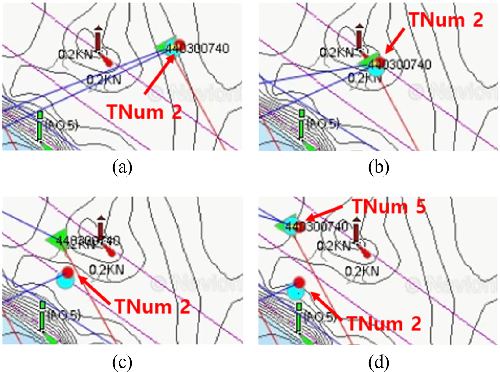
Abnormal phenomenon in Case2; (a) Initial state; (b)State before turning motion; (c) State during turning motion; (d) State after turning motion
Fig. 8 shows the change that occurred based on the number of fusion attempts with regard to the difference (ΔD) between the locations of the vessel obtained from the AIS and ARPA signals (based on the analysis results of Case 2).

Relative distance in Case 2: (a) Relative distance based on the raw data; (b) relative distance based on the processed data
Meanwhile, as shown in Fig. 8(a) for R440300740 (blue circle), the number of fusion attempts increased with an increase in the measurement time, and ΔD rapidly increased owing to abnormal occurrences. Fig. 8(b) shows the application of the proposed technique for the same situation.
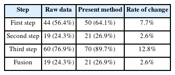
Table 6 lists the success rates of fusion for the total number of attempts (78 times) for the aforementioned circumstance, and the rate was higher when the proposed method was used instead of applying sensor fusion without processing.
4.3 Result and Abnormal Phenomenon of Case 3
In Case 3, an abnormal phenomenon occurred during the fusion attempted for the ARPA radar signal with target number 3 and AIS signal with MMSI 440008970 using the proposed method. Fig. 9 shows the chronological order of the actual measurement phenomenon. Fig. 9(a) shows the initial situation of receiving heterogeneous signals of Case 3, and the rectangle marked in red dotted line shows that the heterogenous signal within the shape is for the same vessel. However, as the data update period (the AIS signal motion data transmission period) passed, the location of the AIS signal was updated (Fig. 9(b)); however, the ARPA radar signal data were updated without changing the location. Considering that the corresponding ARPA radar signals were at a state of halt in this study, this situation was determined as a false setting of a standstill object considered as a target. Therefore, the data of this case were not considered.
4.4 Result and Abnormal Phenomenon of Case 4
In Case 4, the AIS signal with MMSI 440008970 and ARPA signal with target number 4 were successfully fused using the proposed method, and no typical abnormalities were observed. Fig. 10 shows the change based on the number of attempts of fusion with regard to the difference (ΔD ) in the locations of the vessel obtained from the AIS and ARPA signals (based on the analysis results of Case 4).
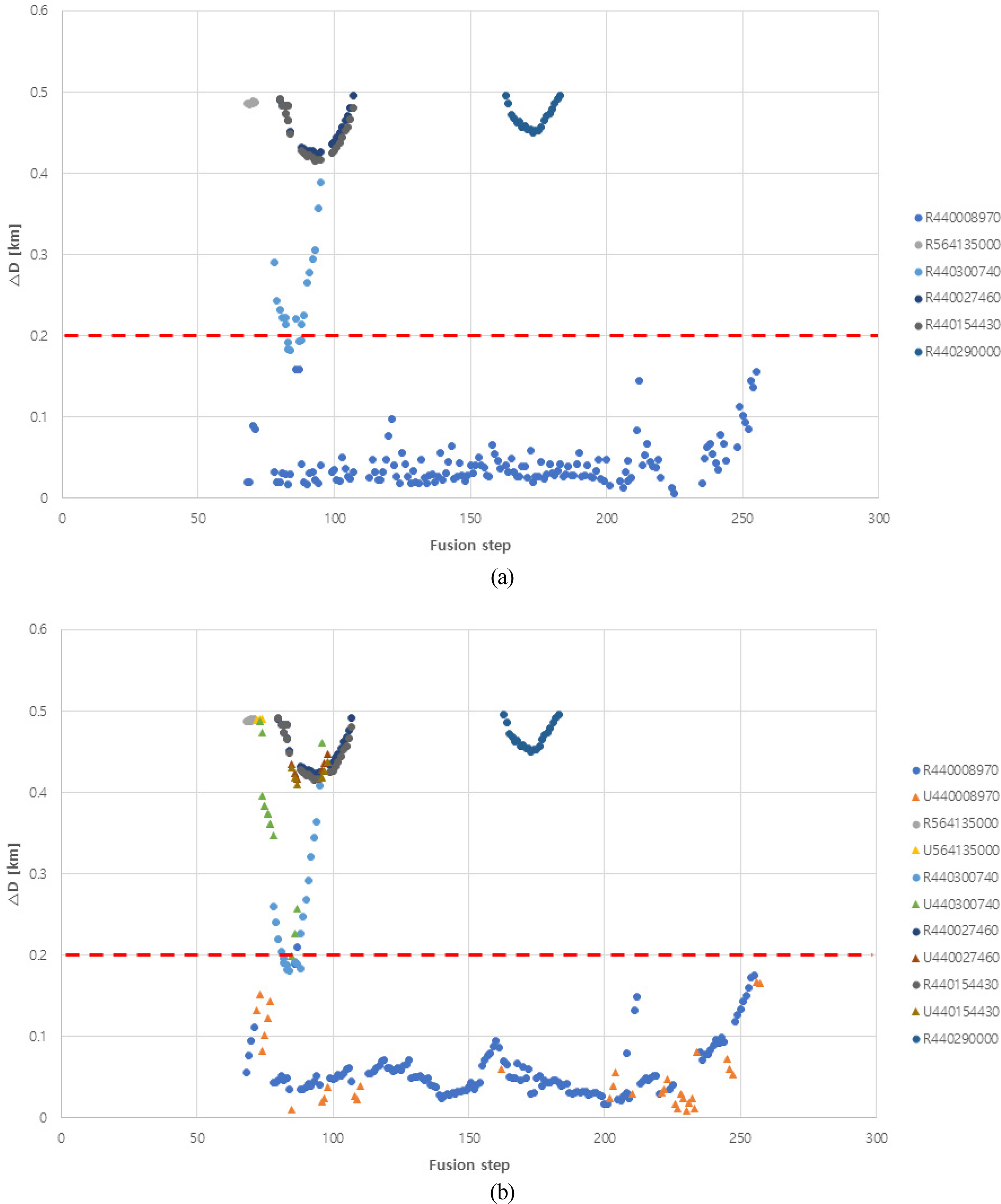
Relative distance in Case 4: (a) Relative distance based on the raw data; (b) relative distance based on the processed data
As shown in Fig. 10(a) (R440008970 (blue circle)), the increase in the measurement time indicated that ΔD varied within the threshold value. Fig. 10(b) shows the case of updating the signal based on the proposed location prediction and object-tracking algorithms for an identical situation, and the change toward the appearance of a data distributional tendency can be identified. Table 7 lists the fusion success rates with respect to the total number of attempts (189 times) for the aforementioned circumstance, and processing as proposed in this study exhibited higher success rates than sensor fusion without any other additional processing.
4.5 Result and Abnormal Phenomenon of Case 5
In Case 5, the AIS signal with MMSI 440300740 and ARPA signal with target number 5 succeeded in fusion using the proposed method, and no typical abnormalities were observed similar to Case 4. Fig. 11(a) shows the change based on the number of attempts of fusion with regard to the difference (ΔD) between the location of own ship and the locations of the vessel obtained from the AIS and ARPA signals (based on the analysis results of the phenomena of Case 5).
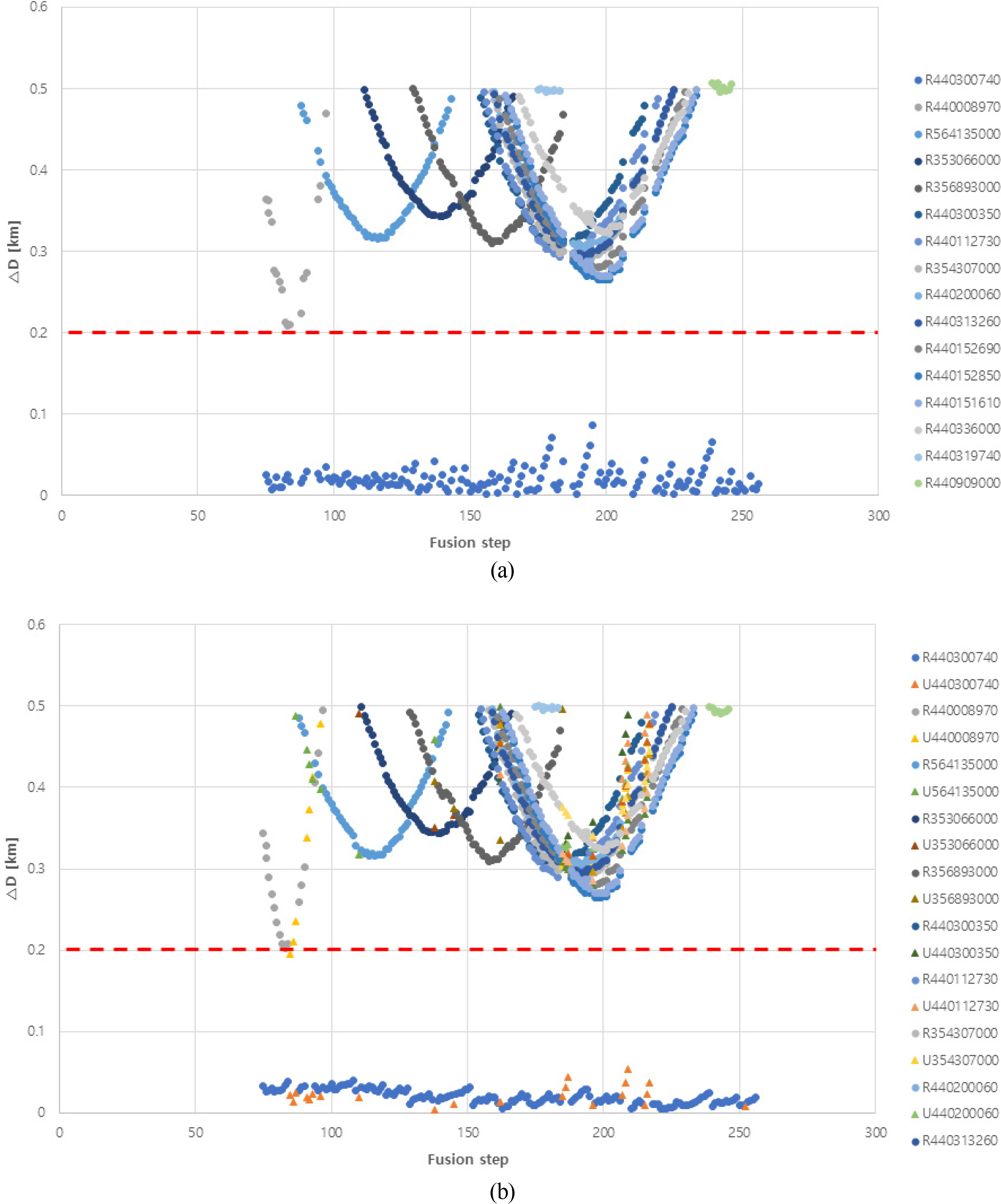
Relative distance in Case 5: (a) Relative distance based on the raw data; (b) relative distance based on the processed data
Meanwhile, as shown in Fig. 11(a) for R440300740, ΔD varied within the threshold value with an increase in the measurement time. Fig. 11(b) shows the case of updating the signals using the location prediction algorithm and the proposed object tracking algorithm for the same situation, from which a change toward data having distributional tendency and reduced range of distributed difference between the heterogenous signal locations can be identified.
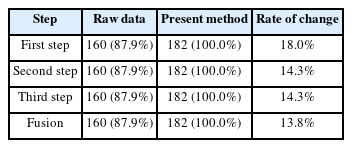
Table 8 lists the rate of success with regard to the attempted fusion (182 times) for the aforementioned situation, and the success rate was higher when the proposed method was applied rather than proceeding with sensor fusion without processing.
5. Conclusions
This study considered the characteristics of ARPA and AIS signals to propose the sensor fusion algorithm that could determine whether two vessels are identical in real time. To overcome the abnormal phenomenon of signals that may occur in real environments, a UK-PDAF-based multiple-object tracking algorithm was developed to track ARPA signals, and an AIS-data-based location prediction technique was used to reduce the number of errors according to the AIS signal period (time). Moreover, the results of the field tests performed (Cases 1, 4, and 5) to verify the validity of the proposed algorithm indicated that an identical vessel can be recognized at an average probability of 95%; Case 2 was excluded because it experienced ARPA malfunctioning, and in Case 3, the target was mistakenly selected. However, owing to the lack of real measurement data, the application of the proposed techniques was limited for numerous cases. Therefore, in the future, a large number of actual measurements will be necessary to verify the utility of the proposed method. Finally, this study performed object tracking again after receiving the tracked results from the ARPA; however, further studies are required to ultimately track objects based on radar images.
Notes
The authors declare that they have no conflict of interests.
This study was sponsored by Daewoo Shipbuilding & Marine Engineering in 2022 and was supported by the Korea Institute of Energy Technology Evaluation and Planning (KETEP) grant funded by the Korea government (MOTIE) (Project Number:20213030020200, Project Name: Development of fully-coupled aero-hydro-servo-elastic-soil analysis program for offshore wind turbine system).


