Onboard CO2 Capture Process Design using Rigorous Rate-based Model
Article information
Abstract
The IMO has decided to proceed with the early introduction of EEDI Phase 3, a CO2 emission regulation to prevent global warming. Measures to reduce CO2 emissions for ships that can be applied immediately are required to achieve CO2 reduction. We set six different CO2 emission scenarios according to the type of ship and fuel, and designed a monoethanolamine-based CO2 capture process for ships using a rate-based model of Aspen Plus v10. The simulation model using Aspen Plus was validated using pilot plant operation data. A ship inevitably tilts during operation, and the performance of a tilted column decreases as its height increases. When configuring the conventional CO2 capture process, we considered that the required column heights were so high that performance degradation was unavoidable when the process was implemented on a ship. We applied a parallel column concept to lower the column height and to enable easy installation and operation on a ship. Simulations of the parallel column confirmed that the required column height was lowered to less than 3 TEU (7.8 m).
1. Introduction
Efforts to respond to climate change are spreading to all industries around the world. In 2015, the Paris Agreement was adopted, aiming toward worldwide efforts to keep the global average temperature rise below 2 °C above the pre-industrial level and further limit the future temperature rise to below 1.5 °C (Bodansky, 2016). To implement this, the International Maritime Organization (IMO) has established and implemented regulations to reduce greenhouse gas (GHG) emissions from ships. According to the third IMO GHG study, CO2 emitted from ships worldwide in 2012 accounted for 2.2% of the total CO2 emissions (IMO, 2014). This exceeds the CO2 emissions of Germany, Canada, and Korea (Olivier et al., 2017). According to the fourth IMO GHG study, CO2 emitted from ships worldwide in 2018 accounted for 2.89% of the total CO2 emissions, showing an increasing trend of the proportion of CO2 emissions from ships. To respond to this, the 2019 Marine Environment Protection Committee (MEPC) 74 determined the introduction time of the Energy Efficiency Design Index (EEDI) Phase 3. The EEDI is an operational efficiency indicator for ships and refers to the CO2 emission when 1 ton of a ship operates for 1 sea mile (1.852 km). The EEDI Phase 3 requires a reduction of 30% or more of CO2 emissions from ships from 2025 to 2030 compared with 2008, and Phase 4, which will be applied after 2030, requires a CO2 reduction of more than 40%. However, the MEPC 75 in 2020 proposed to reinforce emission regulations. Accordingly, part of the EEDI Phase 3, which was originally scheduled to be introduced in 2025, was moved forward to 2022.
Various methods are being devised to reduce GHGs emitted from ships to achieve the IMO’s CO2 emission reduction strategy. According to DNV-GL (2017), the main CO2 reduction methods that have been attempted so far are classified into the following four categories: liquefied natural gas (LNG) with the use of alternative fuels e.g., hydrogen, increased energy efficiency, the reduction of navigation speed, and carbon pricing. Among alternative fuels, LNG is a representative fuel, and extensive reviews have been reported on liquefied petroleum gas, biodiesel, bio methanol, liquefied biogas, hydrogen, and nuclear power. Methods to increase energy efficiency include the development of a new hull form, recycling waste heat, engine overhaul, the development of a hybrid engine, and main engine air lubrication. Combining all these methods can achieve fuel savings of 21% to 37% per ship (Kristensen, 2012). The energy efficiency improvement of ships will continue to rise gradually until 2050 considering improvement measures, such as hull form improvement, the optimization of ship speed and operation, propulsion system, and low/zero-carbon fuels. However, from an operational point of view, the energy efficiency improvement is expected to peak in 2035, and carbon reduction by alternative fuels will dominate afterward (DNV-GL, 2018). Excluding alternative fuels, it is estimated that 20%–30% of current CO2 emissions can be reduced by currently applicable technical and operational measures. In the future, carbon reduction by alternative fuels, such as hydrogen, ammonia, and biodiesel, should be promoted. However, developing and applying related technologies are currently challenging tasks, and the corresponding infrastructure is also insufficient. Therefore, as the effective date of the EEDI Phase 3 has been partially advanced to 2022, an onboard CO2 capture technology that can be applied immediately is required to achieve the target CO2 emission reduction.
Several researchers have studied onboard CO2 capture technology in various ways. Zhou and Wang (2014) proposed a method for capturing and fixing CO2 as calcium carbonate using calcium hydroxide solution and sodium hydroxide. This method was applied to a bulk carrier with an 18,660 kW engine, and the effectiveness and economic feasibility were evaluated. Luo and Wang (2017) simulated the monoethanolamine (MEA)-based post-combustion CO2 capture process and the CO2 storage liquefaction process for a cargo ship with a 17 MW engine. They observed that the carbon reduction rate could only reach 73% when conventional marine energy systems were integrated with the CO2 capture process owing to the limited heat and electricity supply to the CO2 capture process. They also observed that the cost of CO2 capture more than doubled when an additional gas turbine was installed to achieve a carbon reduction rate of 90%. Feenstra et al. (2019) simulated the CO2 capture process based on MEA and piperazine (PZ) using Aspen Plus for 1,280 kW and 3,000 kW class marine engines. Furthermore, they calculated the capital expenditure and operating expenditure required to capture CO2 from ship exhaust gas through the process and suggested the addition of a CO2 capture process and a CO2 storage tank to the existing cargo ship design. Lee et al. (2021) proposed a new EEDI estimation method considering the CO2 capture process and applied it to a 53,200 DWT class ship. They simulated the N-methyldiethanolamine- and PZ-based CO2 capture process and the liquefaction process of the captured CO2 using Aspen Plus and considered a design that placed a liquefied CO2 storage tank on a ship. The calculation results confirmed that the carbon capture ratio required in the CO2 capture process was higher than the actual EEDI reduction rate.
2. Process Model Framework
2.1 Rate-based Model
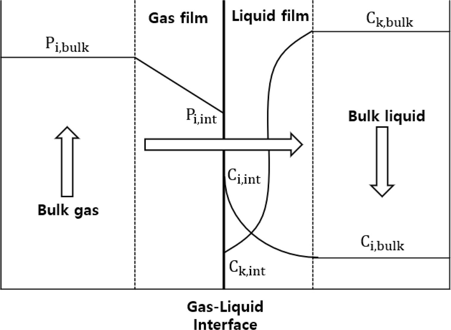
In this study, the CO2 capture process based on an MEA solution was simulated using Aspen Plus v10, a commercial process simulator. Moreover, simulation was performed using a rate-based model for better accuracy. The conventional equilibrium model commonly used for distillation column simulation assumes that gas and liquid phases reach complete equilibrium at each stage and adjusts the performance of the distillation column by introducing an efficiency correction factor in each phase. However, such perfect gas-phase and liquid-phase equilibrium states are rare in actual processes. In contrast, the rate-based model assumes that there are several layers of thin film at the gas–liquid interface according to the film theory as shown in Fig. 1. The Maxwell–Stefan is calculated for this thin film to actualize the realistic heat and mass transfer process at the gas–liquid interface (Al-Baghli, 2001). Through this process, the rate-based model can more closely simulate the chemical reaction in the actual tray column or packed column. When simulating processes with active chemical reactions, such as the CO2 capture process using amines, the rate-based model shows higher reproducibility than the equilibrium model (Zhang and Chen, 2013).
2.2 Thermodynamic Model
Chemical reactions in the liquid phase must be considered to simulate the chemical equilibrium between gas and liquid accurately. The CO2 capture process using amines shows a nonideal behavior owing to its own chemical reaction and ions participating in the reaction. The electrolyte nonrandom two-liquid Redlich–Kwong state model was used to simulate the activity coefficient, Gibbs energy, enthalpy, and entropy of the liquid phase. Furthermore, the fugacity coefficient of the weather (Agbonghae et al., 2014) was simulated using the perturbed-chain statistical associating fluid theory model. The CO2 absorption reaction using MEA is expressed by the equilibrium Eqs. (1)–(5) below.
2.3 Reaction Kinetic Model
In Aspen Plus, the reaction rate rj of a chemical reaction is expressed using a power law as follows:
The chemical reaction of carbamate and bicarbonate formed by the CO2 absorption reaction using MEA are shown in Eqs. (7)–(10).
Zhang et al. (2009) converted the molarity-based speed constant to activation-based speed constant through the experimental data of Hikita et al. (1979) and Pinsent et al. (1956). Therefore, the calculation method of the equilibrium constant is based on “mole gamma.” This result is summarized in Table 1.
3. Validation of Process Simulation
3.1 Target Plant for Simulation Validation
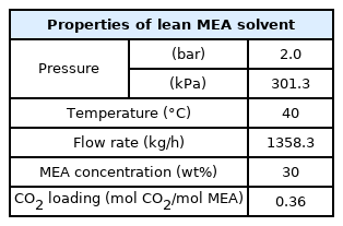
The CO2 capture process was simulated based on pilot plant operational data (Stec et al., 2015) to validate the process simulation prior to simulating the onboard CO2 capture process. The pilot plant to be verified implements a post-combustion carbon capture process based on a 30 wt% MEA solution. Table 2 lists the physical quantities and composition of the acid gas, Table 3 lists the physical quantities of the aqueous amine solution, and Table 4 lists the detailed operating characteristics of the absorber and stripper. The acid gas contains 13.5 mol% of CO2, and the flow rate can be changed in the range of 200–400 kg/h. The absorber is a packed column with a diameter of 0.33 m and a height of 5.1 m filled with Sulzer Mellapak 500Y and 750Y. The stripper is a packed column with a diameter of 0.28 m and a height of 4.3 m filled with Sulzer Mellapak 750Y. The pilot plant was operated by applying various process improvement methods. The process simulation was validated using the amine process operation data of the most popular standard method.
3.2 Result of Simulation Validation
Various correction coefficients, correlation coefficients, and correlation methods of the rate-based model should be carefully selected and adjusted to construct a realistic process model that simulates real chemical reactions well. Table 5 summarizes the main tunable parameters and correlation method of the Aspen Plus rate-based model used to simulate pilot plant operation data. According to Zhang et al. (2009), when the Onda correlation method (Onda et al., 1968) is used, there is a possibility of underestimating the interfacial area. Therefore, the Bravo correlation method (Bravo et al., 1985) was used instead of the Onda correlation method which is generally used as the interfacial area method and mass transfer coefficient method. (Agbonghae et al., 2014). The Stichlmair method (Stichlmair et al., 1989) was used for liquid holdup, and the heat transfer coefficient was used by the Chilton and Colburn method (Chilton and Colburn, 1934). According to Zhang et al. (2009), the prediction accuracy of the countercurrent flow model is the highest, but this model requires a large number of calculations and sometimes shows unstable calculation results. Therefore, the Vplug flow model, which produces stable results, was used.
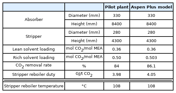
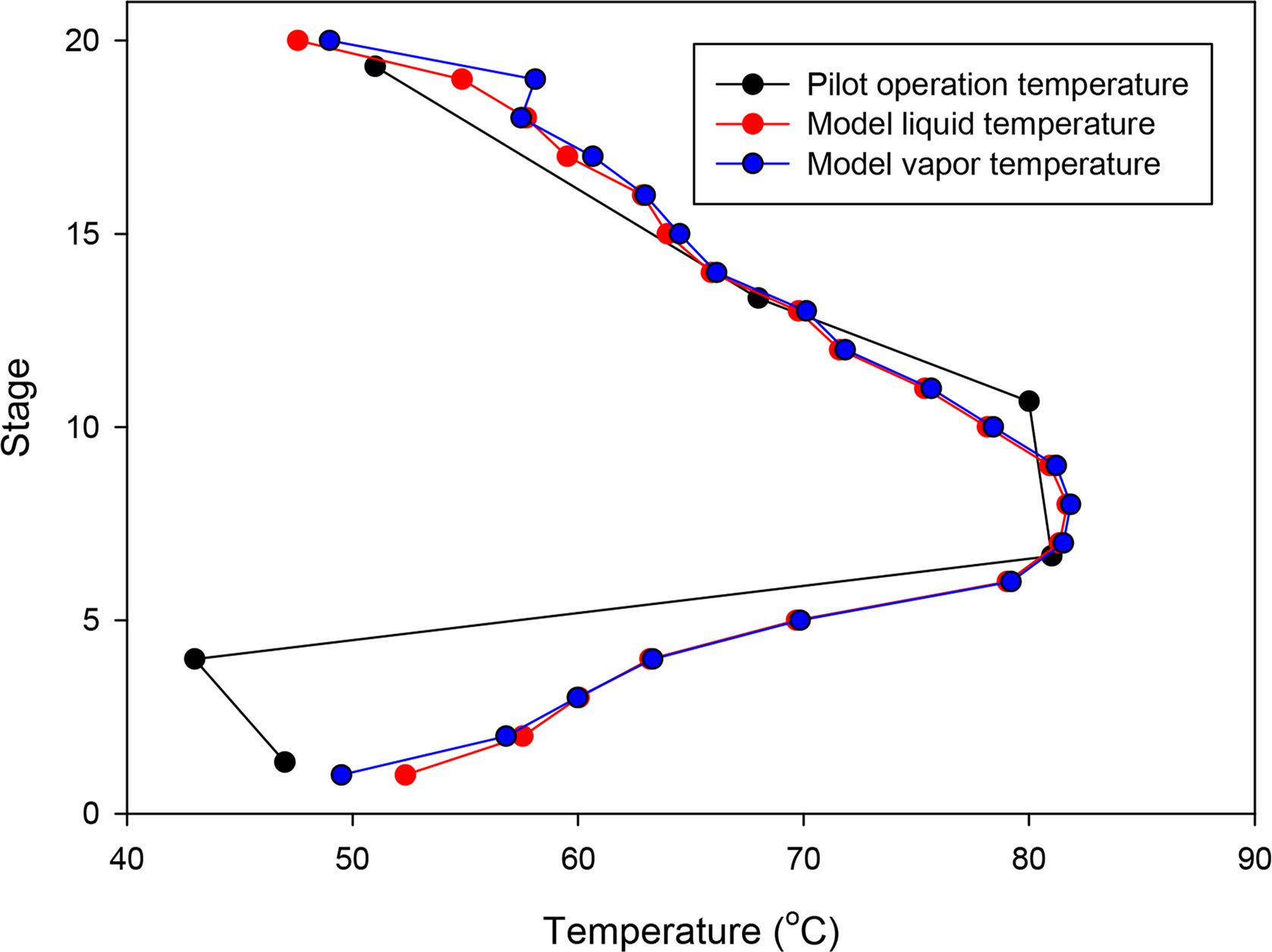
Table 6 lists the simulation results based on the configuration of the Aspen Plus model described above in comparison with the pilot data. Fig. 2 compares the temperature profile inside the actual pilot plant absorber with that of the simulation. The temperature decrease at the fourth stage of the pilot plant absorber could not be simulated. However, it can be seen that the maximum temperature bulge of 7th to 9th stages formed by the CO2 absorption reaction of the amine aqueous solution and the overall temperature trend were well simulated. From the above results, it can be confirmed that the simulation method predict the actual data from pilot-plant very well.
4. Simulation Result of Onboard Carbon Capture Process
4.1 Selection of Onboard CO2 Emission Scenarios
The EEDI is an efficiency indicator determined as follows. First, the CO2 emissions from the main engine, the CO2 from the auxiliary
The CO2 emitted from ships can be estimated using the following equation:

Average power of diesel engines by ship type (kW) (U.S. Environmental Protection Agency, 2009)

Average load factor of diesel engines by ship type (U.S. Environmental protection Agency, 2009; ENTEC, 2007)

CO2 emission factor of four-stroke engine (g/kWh) (Kristensen, 2012)
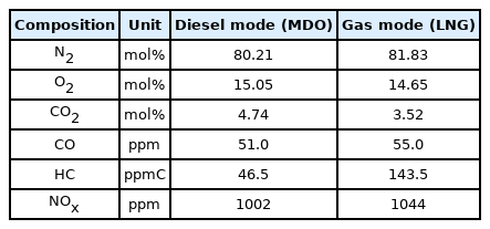
Flue gas compositions of MAN B&W ME-GI engine (Kristensen, 2012)
The IMO presented the EEDI reference line as an exponential function as shown in Table 11 according to the ship type and tonnage, and specified the target reduction rate compared with the EEDI reference line according to the ship type and tonnage. Table 12 summarizes the EEDI Phase 3 target reduction rates by major ship type.
According to the third IMG GHG study, three ship types, i.e., bulk carrier, tanker, and container ship, account for 60% of the total onboard carbon emissions. Therefore, a total of six onboard emission scenarios were selected for the case of using diesel and LNG as fuel for each of the three ship types: bulk carrier, tanker, and container ship. Scenarios 1, 2, and 3 were selected for bulk carriers, container ships, and tankers using diesel as fuel, respectively. In addition, scenarios 4, 5, and 6 were selected for bulk carriers, container ships, and tankers using LNG as fuel, respectively. Table 13 lists the EEDI values for each of the six scenarios based on the above data related to CO2 emission from ships. The tonnage of the ship used in the EEDI calculation was interpolated using the tonnage-engine output data of the Environmental Protection Agency (2009). For the Vref of the ship, the speed of the ship was set to 0.75 MCR (maximum continuous rated) proposed by Notteboom and Carriou (2009). Furthermore, the EEDI reference according to the tonnage and ship type for each scenario was calculated. Finally, the target EEDI required for the EEDI Phase 3 was calculated, and the required CO2 reduction rate to achieve this goal is listed in Table 13.
Then, based on the above data on ship CO2 emissions, the CO2 emissions and total exhaust gas flow rate of each scenario were calculated and summarized in Table 14. As listed in Table 13, the CO2 reduction rate required in the scenario using diesel as fuel is 40%–50%. Hence, the target CO2 reduction rate in the diesel scenario was set to 50%. Similarly, the CO2 reduction rate was set to 30% because the CO2 reduction rate required in the scenario where LNG is used as fuel is 20%–30%. The target CO2 reduction rates for each scenario are summarized in Table 14.
4.2 Simulation of Single Packed Column Process
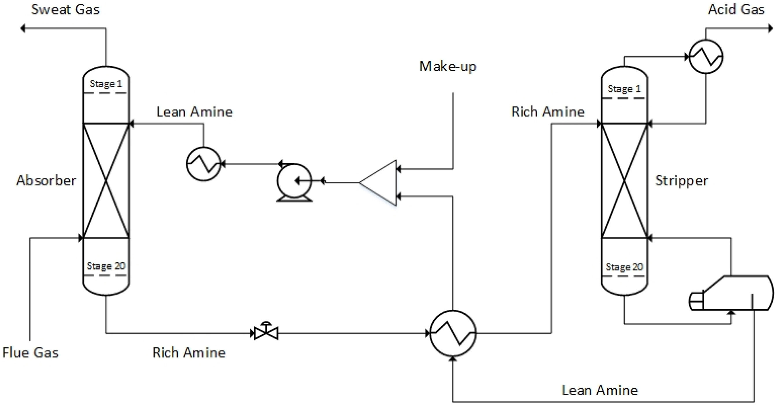
Fig. 3 shows a flowchart of the simplest and most traditional type of CO2 capture process using an aqueous amine solution. The process consists of two packed columns or tray columns and a heat exchanger. As the aqueous amine solution (lean amine) passes through the absorber, it absorbs CO2 from the acid gas. The aqueous amine solution that has absorbed CO2 (rich amine) is introduced into the stripper through the heat exchanger. The reboiler of the stripper performs high-temperature distillation to separate CO2, which is then discharged to the top of the stripper. The regenerated aqueous amine solution passes through the heat exchanger and returns to the absorber.
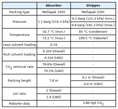
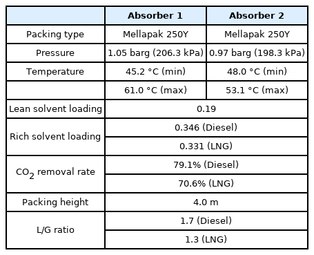
For six onboard CO2 emission scenarios, an onboard CO2 capture process that removes 70% to 80% of CO2 trapped in acid gas using a 30 wt% MEA solution was simulated based on the various coefficients and methods of the rate-based model used for simulation validation in the previous section. The removal rate of the CO2 capture process using the MEA solution is generally set to 90%. However, when the removal rate is decreased, the amount of fluid flowing into the absorber increases. Hence, the diameter of the absorber increases, whereas the height of the absorber decreases. A removal rate lower than 90% was set to design an absorber with a lower height, and the reason will be described below. The absorber is packed with the filler material of Mellapak 250Y, and both diesel and LNG fuel usage scenarios are packed to 7.8 m. The exhaust gas cooled to 40 °C flows into the bottom of the absorber, and the MEA solution cooled to 45 °C flows into the top of the absorber. The stripper is packed with Mellapak 250Y to 4.1 m in the diesel scenario and 4.0 m in the LNG scenario. The MEA solution is heated to 109.5 °C through the reboiler at the bottom of the stripper. For both absorber and stripper, the maximum flooding rate was set to 75%. Detailed operation information of each column is summarized in Table 15, and the process operation flow rates and target CO2 removals are summarized in Table 16. The composition of flue gas CO2 of diesel fuel is 4.74 mol%, and the composition of flue gas CO2 of LNG fuel is 3.52 mol% (Table 10). When diesel is used as fuel, the flow rate of flue gas and CO2 emission are higher than those when LNG is used as fuel.
The lean loading (mol CO2/mol MEA) of the MEA solution flowing into the absorber should be considered carefully because it is one of the major factors influencing the overall process, including the flow rate of the MEA solution, the size of the absorber and stripper, and the amount of heat consumed in the reboiler of the stripper. Fig. 4 shows the effect of lean loading on the flow rate of the MEA solution required and the amount of heat consumed in the reboiler. The lowest energy consumption is 3.80 GJ/t CO2 for the lean loading of 0.19 mol CO2/mol MEA. Therefore, the lean loading of the MEA solution simulating the onboard CO2 capture process was fixed at 0.19 mol CO2/mol MEA, which requires the lowest amount of energy. At a lean loading below 0.19 mol, the required flow rate of the MEA solution decreases, whereas the CO2 absorption performance and speed increase; however, the amount of heat consumed to regenerate the MEA solution increases exponentially. This is because more energy is required to achieve a lower level of CO2 loading when rich MEA that has absorbed CO2 is regenerated in the stripper. If the lean loading increases, the required flow rate of the MEA solution increases. This in turn increases sensible heat, the overall size of the equipment, and the risk of column flooding.
Table 17 lists the size results of simulating the CO2 capture process according to the aforementioned six onboard CO2 emission scenarios. The size simulation of the device was performed using the Aspen process economic analyzer installed as an add-on of Aspen Plus. The flow rate of exhaust gas varied considerably according to each scenario, and the column diameter changed significantly as a result. In both the diesel and LNG scenarios, the absorber height was the same at approximately 12.2 m. The height of the stripper was approximately 8.5 m for the diesel scenario and approximately 8.4 m for the LNG scenario. This is because the lean solvent loading was the same in both scenarios, but the partial pressure of CO2 of the aqueous amine solution flowing into the stripper was different. Furthermore, the overall column height was significantly increased by additional devices installed in the columns compared with the height of the filler in each case.
The onboard CO2 capture process assumed in this study aims to demonstrate the possibility of implementing a simple CO2 capture process without extensive remodeling for ships beyond EEDI Phase 3 among existing ships. However, the calculated column height exceeded 8 m in all scenarios, and the height of the absorber in particular reached 12.2 m. Assuming that all the above scenarios are for small- and medium-sized ships, there is a possibility that such a high column height may exceed the height of the engine room or the height of the stack. This indicates that, to implement the CO2 capture process, extensive repair and maintenance of the ship are required, such as making a hole in the ship’s deck or expanding the stack. Moreover, the hull is inevitably inclined owing to six-degree-of-freedom motions, such as roll, pitch, and yaw, which is unavoidable for the ships floating on the water during operation. Consequently, as the absorber installed on the ship is tilted, it is likely that the CO2 absorption performance will decrease (Di et al., 2018). According to Son et al. (2017), maldistribution of liquid inside a tilted column increases significantly as the packed column height increases. This interferes with smooth process operation and decreases column performance. Therefore, in this study, a parallel column CO2 capture process with two absorbers and two strippers was newly simulated with the objective of implementing a CO2 capture process in which the height does not exceed 3 TEU (TEU indicates the size of a standard container, and the height of 3 TEU is 7.8 m).
4.3 Simulation of Parallel Packed Column Process
Absorber intercooling is an improved absorber process operation method widely used to increase the efficiency of the on-shore CO2 capture process using amines. This method forms a temperature imbalance inside the absorber because the CO2 absorption reaction by amines is an exothermic reaction. In general, the highest temperature in the absorber is generated in the middle part of the absorber. The absorber intercooling process decreases the overall temperature of the fluid inside the absorber by installing a cooler in this highest-temperature part to provide a cooling circulating flow inside it. CO2 absorption reaction using amines occurs more actively in an environment with a low temperature owing to the solubility of gas. Hence, the installation of an intercooler increases the CO2 absorption capacity of the aqueous amine solution. Therefore, the intercooling process can have positive effects, such as reductions in the flow rate of the aqueous amine solution required for CO2 capture, the overall size of the equipment, the energy consumption of the reboiler, and process operation cost.
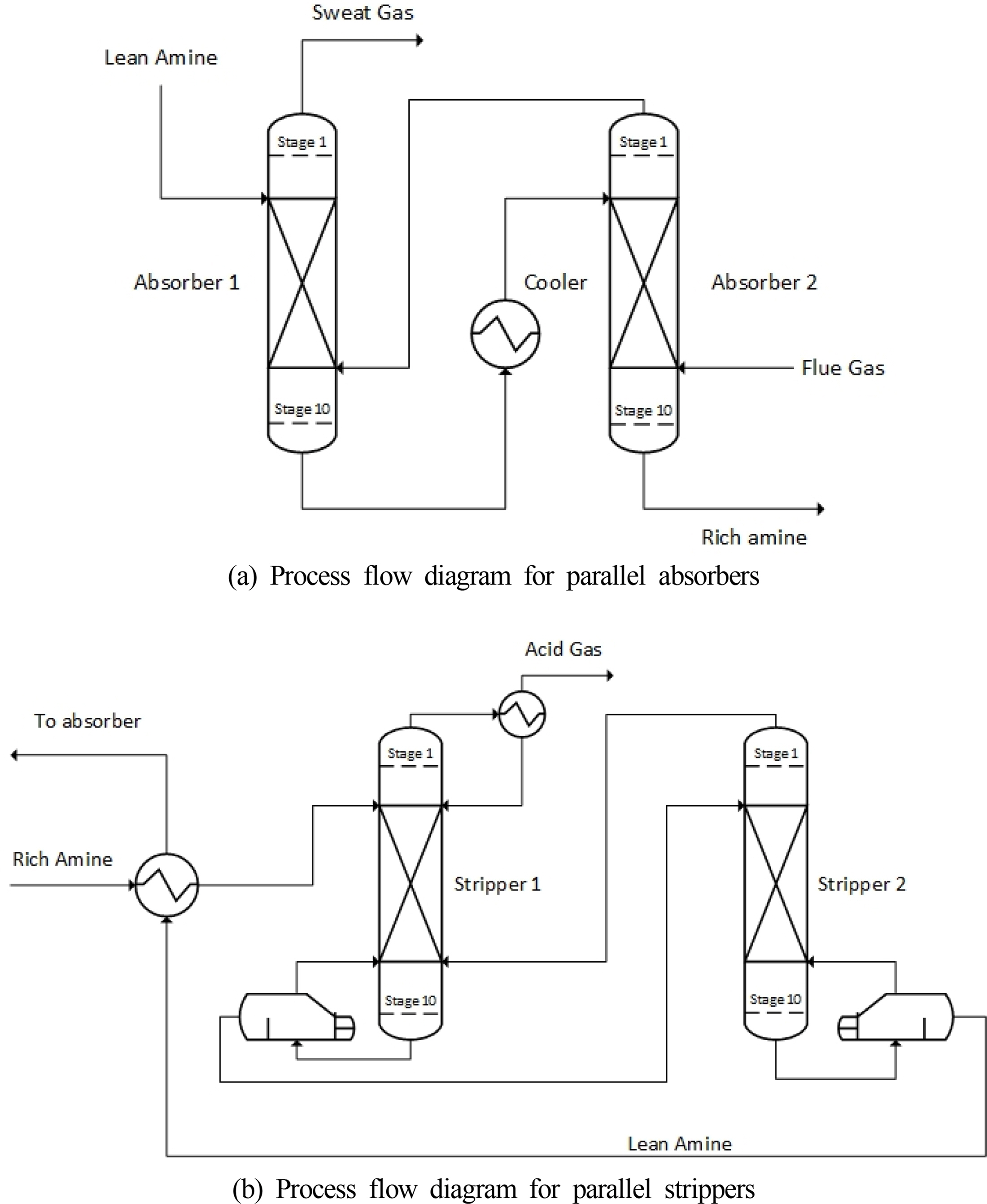
A parallel absorber using an intercooling device was devised to lower the column height required for the onboard CO2 capture process based on the basic concept of the absorber intercooling process. As shown in Fig. 5(a), the regenerated aqueous amine solution flows into the upper part of the first absorber, and the gas from which CO2 is removed is discharged through the upper part of the first absorber. The aqueous amine solution that has slightly absorbed CO2 comes out from the bottom of the first absorber, passes through the cooler, and flows into the top of the second absorber at a low temperature. The exhaust gas flows into the bottom of the second absorber, and the aqueous amine solution that has completely absorbed CO2 is discharged from the bottom of the second absorber.
Fig. 6(a) shows the temperature gradient inside the absorber in a single absorber process. A relatively low temperature is maintained at the top and bottom of the absorber because the inflow of the low-temperature MEA solution and exhaust gas continues. However, the temperature of the fluid inside the absorber rises owing to the CO2 absorption reaction of MEA, which is an exothermic reaction, and the highest temperature of 72.5 °C can be observed near stage 5. Fig. 6(b) shows the temperature gradient inside the absorber in the parallel absorber process. Stages 1 to 10 represent the first absorber, and stages 11 to 20 represent the second absorber. A low temperature is maintained in stages 1 and 20, where the MEA solution and exhaust gas are introduced, as well as in stages 10 and 11, which pass through the cooler. Hence, the maximum temperature of the entire absorber remains at approximately 61 °C. The absorption performance of the MEA solution also increased, which was able to reduce the total MEA solution flow rate by 12%.
In Figs. 6 (a) and (b), the temperature of the incoming MEA solution is 40 °C in both cases. However, the temperatures of the single absorber in stage 1 are 52.8 °C (liquid) and 60.8 °C (gas), and the temperatures of the parallel absorber in stage 1 are 45.2 °C (liquid) and 49.6 °C (gas). This is because stage 5, the point at which the reaction occurs most actively in the absorber, is close to stage 1, the inlet of the MEA solution; therefore, the temperature of stage 1 changes relatively significantly according to the maximum internal temperature of the absorber. As the maximum temperatures inside the single absorber and the parallel absorber differ by approximately 10 °C, the temperature of stage 1, which is close to temperature bulge, also shows a difference of approximately 5–10 °C. The basic concept of stripper interheating is the same as that of absorber intercooling. A heater is installed in the middle of the stripper to raise the overall temperature of the stripper. The amine solution that absorbs CO2 is heated in the stripper to separate the absorbed CO2. The regeneration efficiency increases if a higher temperature is maintained up to the top of the stripper. This can be expected to reduce the energy consumption in the reboiler and the size of the stripper. Based on this concept, the rich MEA solution is introduced at the top of the first stripper and the separated CO2 is discharged as shown in Fig. 5(b). The MEA solution heated by the reboiler at the bottom of the first stripper flows into the top of the second stripper. At the bottom of the second stripper, the MEA solution after CO2 separation flows to the absorber through the heat exchanger.
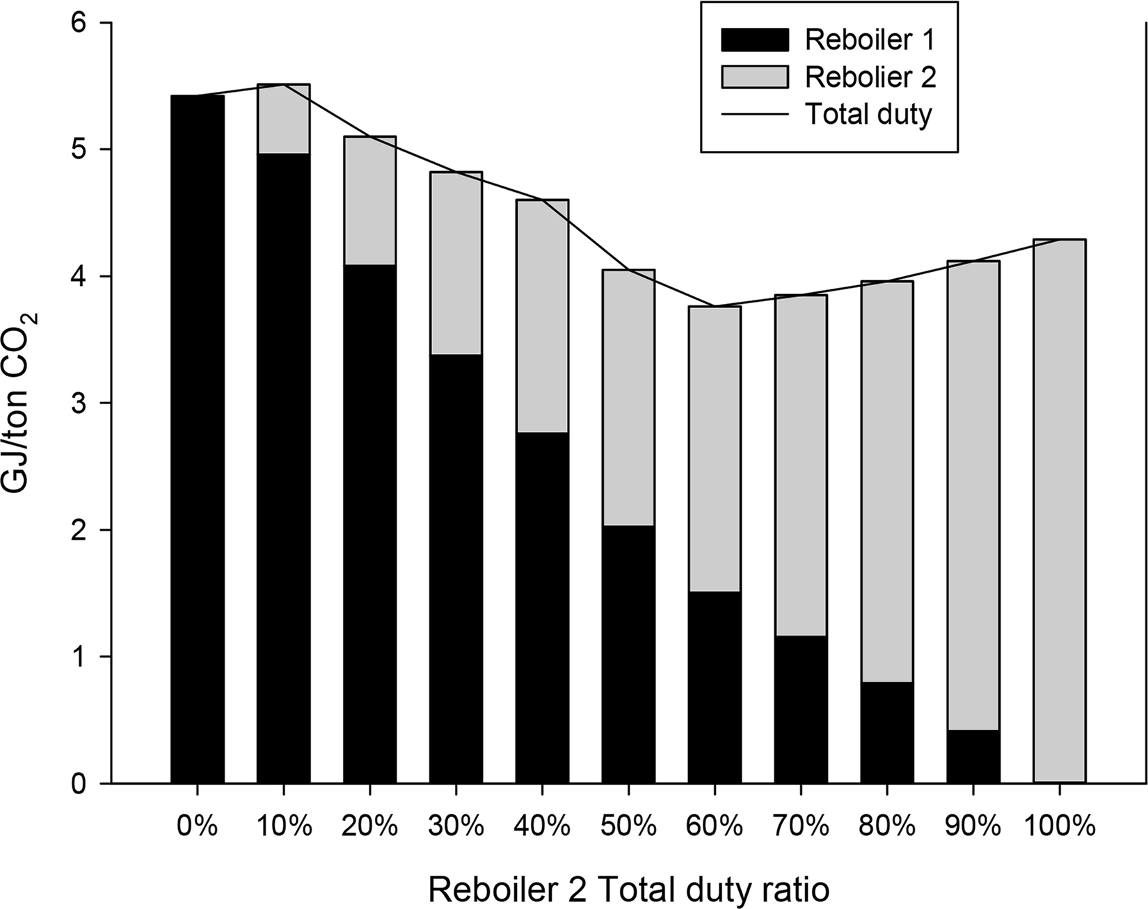
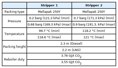
Fig. 7 shows the energy consumption required to achieve the same lean CO2 loading according to the ratio of energy consumed by the reboiler of each stripper. The x-axis represents the ratio of energy consumption of the reboiler of the second stripper to the total energy consumption. The y-axis represents the total energy consumption. The amounts of energy consumed by the first and second reboilers, respectively, are shown in different colors. A relatively high energy consumption can be observed at 0%–10% when the reboiler of the second stripper is used less or is not used. This indicates that inefficient energy input is required to heat the bottom of the second stripper sufficiently only with the reboiler of the first stripper. The overall energy consumption decreases as the proportion of energy consumption of the reboiler of the second stripper gradually increases, reaching a minimum of 3.76 GJ/t CO2 at 60%. Beyond the proportion of 60%, the total energy consumption increases again. This appears to be because a relatively large amount of energy is input to heat the top of the first stripper sufficiently with the reboiler of the second stripper. Therefore, in the parallel absorber process, the ratio of energy consumption of the reboiler of the first stripper and the reboiler of the second stripper was simulated as 4:6. Tables 18 and 19 list the detailed operational information of the parallel packed column process.
Table 20 lists the process simulation size results for the six scenarios of the CO2 capture process for parallel packed columns. The diameters of both the absorber and stripper changed according to the flow rate of each scenario. When compared with the single absorber process, the flow rate of the MEA solution decreased, and the overall diameter of the column decreased as a result. The absorber heights in both scenarios were approximately 7.6 m, which were much lower than the height of the single packed column, i.e., 12.2 m. Thus, the column height was simulated to be lower than the intended height of 3 TEU (7.8 m). The height of the stripper was simulated as approximately 6.5 m in the diesel scenario and approximately 6.4 m in the LNG scenario, which were lower than 8.5 m and 8.4 m for the single packed column, respectively, and also lower than the target height of 3 TEU.
4. Conclusions
A technology to reduce CO2 emissions that can be immediately applied is required owing to the expedited implementation of the EEDI Phase 3. Thus, in this study, an MEA-based onboard CO2 capture process was simulated and the required column size was examined. Before the simulation, the average CO2 emission according to the ship type was calculated, and the amount of CO2 reduction required for the implementation of the EEDI Phase 3 was calculated. Six scenarios were defined according to ship type and fuel, and the MEA-based onboard CO2 capture process required for these scenarios was simulated. The process simulation was conducted using the rate-based model of Aspen Plus v10, a commercial process simulator. The operational data of the pilot plant were used to verify the accuracy and reproducibility of the process simulation. Various correction factors and correlation methods of the rate-based model were carefully adjusted and selected based on the operation data of the pilot plant. The results of process simulation were validated by comparing them with the operation data. The MEA-based CO2 capture process required for the six onboard CO2 emission scenarios selected above was simulated through the adjusted rate-based model. The onboard CO2 capture process was designed to include the most widely used basic types of absorber, stripper, and heat exchanger. Furthermore, the CO2 reduction rate of 70%–80% was targeted based on lean loading with the minimum energy consumption in the reboiler. The result of process simulation confirmed that an absorber and a stripper with a diameter of approximately 0.7 m–3.6 m and a height of 8.4 m–12.2 m were required depending on the scenario.
A lower column height in the onboard CO2 capture process is more advantageous owing to the characteristics of ships. The column height of up to 12.2 m in the onboard CO2 capture process simulated above was too high for implementation on a ship. Therefore, to lower the column height, an onboard CO2 capture process using parallel packed columns was newly designed and simulated. Both the absorber and stripper were designed to have two parallel columns, and each column was connected by applying the intercooling and interheating concepts. Consequently, the onboard CO2 capture process could be configured with columns having a diameter of approximately 0.7 m–3.5 m and a height of 6.4 m–7.6 m. Therefore, immediate onboard application would be possible because the column height is less than 3 TEU or 7.8 m. However, the CO2 capture process with parallel packed columns increases the space required for installation, as the required number of columns increases compared with that in the conventional process. This is a disadvantage, as ships have several spatial constraints. Therefore, the size of the engine room, the location of the stack, and the arrangement of the deck structure should be carefully considered to apply the parallel column process to an actual ship.
The CO2 capture process using amines requires a considerable amount of heat to regenerate the aqueous amine solution owing to the nature of the process. It is assumed that the thermal energy required for the onboard amine CO2 capture process is supplied through the waste heat of the engine and exhaust gas. However, an auxiliary engine is required to generate additional power if sufficient waste heat is not supplied to regenerate all the aqueous amine solution. This additional power generation results in higher CO2 emissions than before. Therefore, the target CO2 removal to achieve the EEDI Phase 3 will be higher than that initially calculated. This aspect requires a close review because it leads to additional increases in load and size in the capture process. Therefore, further studies are required to optimize the energy flow of the process and to design the process considering the additional energy required by the implementation of the onboard CO2 capture process.
Notes
No potential conflict of interest relevant to this article was reported.
This research was supported by a grant (RS-2022-00143644) funded by Ministry of Land, Infrastructure and Transport of Korean government.

