Experimental Study on Application of an Optical Sensor to Measure Mooring-Line Tension in Waves
Article information
Abstract
Moored floating platforms have great potential in ocean engineering applications because a mooring system is necessary to keep the platform in station, which is directly related to the operational efficiency and safety of the platform. This paper briefly introduces the technical and operational details of an optical sensor for measuring the tension of mooring lines of a moored platform in waves. In order to check the performance of optical sensors, an experiment with a moored floating platform in waves is carried out in the wave tank at Changwon National University. The experiment is performed in regular waves and irregular waves with a semi-submersible and triangle platform. The performance of the optical sensor is confirmed by comparing the results of the tension of the mooring lines by the optical sensor and tension gauges. The maximum tension of the mooring lines is estimated to investigate the mooring dynamics due to the effect of the wave direction and wavelength in the regular waves. The significant value of the tension of mooring lines in various wave directions is estimated in the case of irregular waves. The results show that the optical sensor is effective in measuring the tension of the mooring lines.
1. Introduction
A moored floating platform has great potential in ocean engineering applications because a mooring system is necessary to keep the floating platform in station. In order to do this, the tension of the mooring line is investigated to ensure its bearing capacity. Kim et al. (2005) investigated the mooring dynamics in wind, waves, and currents through a simulation and experiment. In addition, the mooring tension from the simulation’s results was compared with experimental results. The effect of the position of the mooring line on the dynamic responses of the spar platforms was studied by Montasir et al. (2015). The platform was connected with asymmetric and symmetric mooring configurations. The dynamic responses of the spar were estimated based on the tension of the mooring lines. Natarajan and Ganapathy (1997) performed a model test on a moored ship to measure the tension of the mooring lines. The model test was carried out with two types of the mooring configurations: spread mooring and berth mooring. The experiment was performed in head sea in various environmental conditions of wind, waves, and current. Other studies on the hydrodynamic characteristics of a moored platform in freak waves were conducted (Pan et al., 2018; Pan et al., 2021). The tension of the mooring line response was increased significantly under the effect of freak waves. In addition, the dynamic response and the tension of the mooring line in the freak waves were compared to that in irregular waves. Cevasco et at. (2018) studied the dynamic response of a floating offshore wind turbine system by conducting a numerical simulation. Two different versions of the mooring dynamics were compared. Paduano et at. (2020) conducted an experiment and numerical simulation to investigate the dynamic motion and tension of floating wave energy converters. Three models of mooring lines were studied. Kim et al. (2016) investigated the anchor tension of a tension leg platform by conducting an experiment and simulation. The anchor tension in regular waves with wind was estimated. The experimental result and simulation result of the anchor tension were compared. Jiang et al. (2020) conducted a numerical simulation using Reynolds-averaged Navier-Stokes (RANS) to investigate a dynamic mooring system, and a coupled methodology potential was used for estimating the moored offshore structures.
The development of optical sensor technology has advanced since the beginning of research on fiber Bragg grating (FBG) sensors by Meltz et al. (1989) and Hill and Meltz (1997). However, the optical sensor has only been applied in the field of naval architecture in recent years. Chung et al. (2021) performed a longitudinal tension experiment to measure the tension of a sample mooring line. An optical sensor was integrated into the mooring line to measure its tension. However, the longitudinal tension experiment just measured the increased loading force without any dynamics of the mooring line. Therefore, it is necessary to investigate the effect of dynamic loading force on the optical sensor.
In order to accurately estimate a mooring line’s tension, some sensors are used directly in the mooring line. Most research has used a tension gauge to measure the tension in a mooring line. In the present study, an optical sensor was developed to measure it. The rest of the paper is structured as follows. First, the technical and operational details of the optical sensor are introduced. Second, an experiment with a moored floating platform is presented to check the performance of the optical sensor. The tension of mooring lines measured by the optical sensor and tension gauge are compared. The maximum tension of the mooring lines is estimated to investigate the mooring dynamics due to the effect of the wave direction and wavelength in regular waves. Finally, the significant value of the mooring line’s tension in various wave directions is estimated in irregular waves.
2. Optical Sensor
2.1 Characteristic and Technical of Optical Sensor
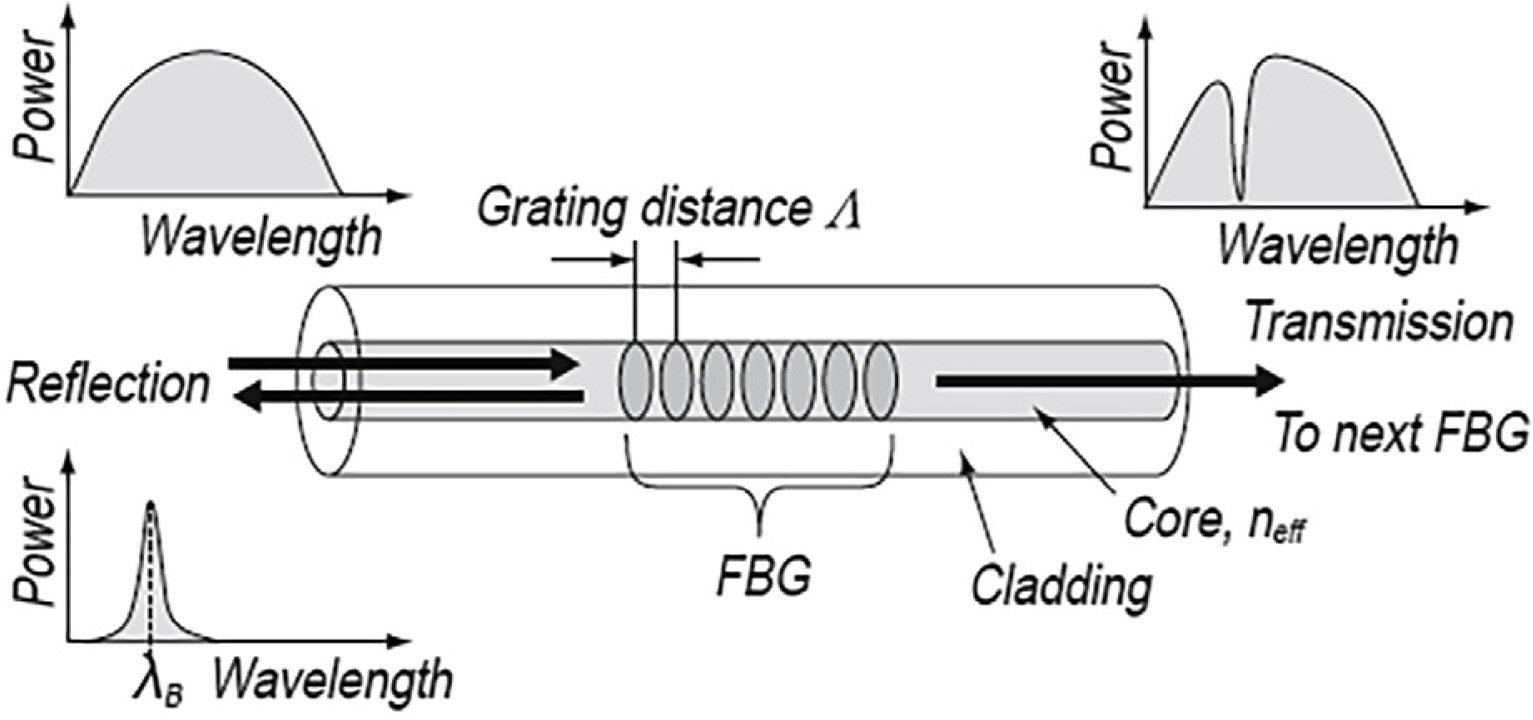
Fiber-optic strain sensors are among the optical sensors that have recently gained attention across various fields. They have been classified as high intensity, interferometric, and FBG sensors based on the measurement method. Distributed sensing technology has recently been developed since the popularization of optical components by Culshaw and Kersey (2008). An optical sensor has the following advantages: it is unaffected by external electromagnetic waves, it can transmit signals over long distances, and it enables multiplexing, making it convenient to connect numerous sensors due to their structural characteristics. They also have remarkable durability and a life of 20 years. In civil engineering, FBG sensors have been used to monitor large structures, such as bridges and tunnels, and they have recently been applied in mechanical engineering. An FBG creates a permanent refractive index modulation on the core in the longitudinal direction of the optical sensor, and this modulation is used as a sensor. Fig. 1 shows a schematic of an FBG structure. When a periodic refractive index modulation is made, coupling is generated between the propagation mode and the reflection mode, so a particular wavelength is reflected.
2.2 Operational Principle of Optical Sensor
The reflected wavelength by an FBG is determined by the spacing and refractive index modulation of the core. Eq. (1) is used to describe this property:
2.3 Design and Fabrication of Optical Sensor
A photosensitive single-mode optical fiber that responds to light in the ultraviolet region is used to produce an FBG. Photosensitivity is increased by injecting hydrogen into the core at high pressures or by doping with Ge. A phase mask is used to create a periodic refractive index modulation in an optical fiber with increased photosensitivity.
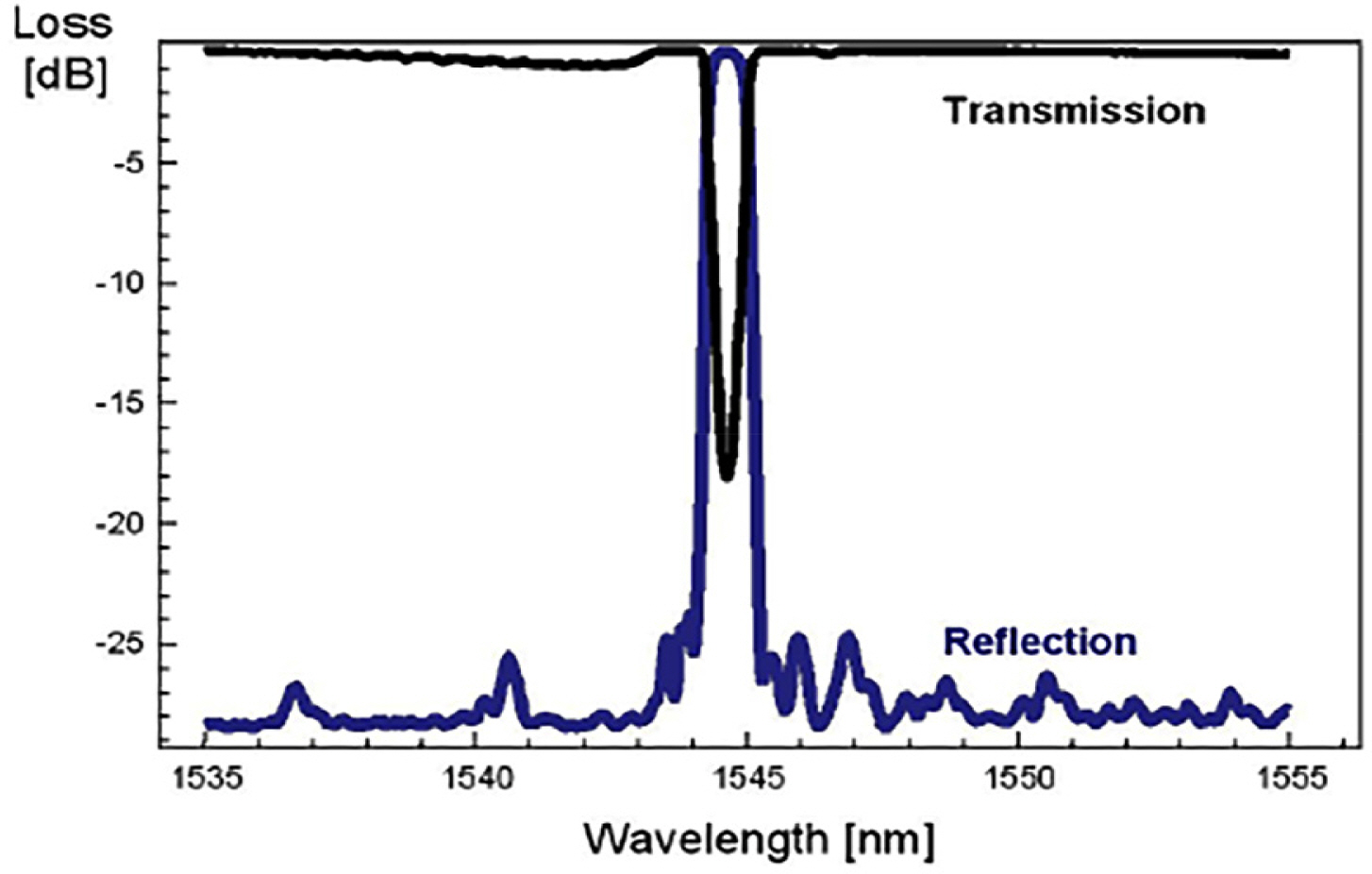
The phase mask generates a periodic interference shape through the diffraction effect of light. As shown in Fig. 2, an excimer that generates light within the range of 190–250 nm and an argon laser with a frequency doubler are used to generate ultraviolet light, which is transmitted through the phase mask on the photosensitive optical fiber. The pattern with periodic intervals passing through the phase mask generates a periodic refractive index modulation in the optical fiber, thus producing the FBG. Fig. 3 shows the wavelength characteristics of the produced FBG.
As shown in Fig. 3, the light reflected by the optical sensor grating is transmitted in the direction of the incident optical fiber. Then, it is reflected and returns with the physical quantity information to the point where the FBG is located. The sensors can be multiplexed, assuming that the structure has light sources that can generate various light types and that gratings with different Bragg center wavelengths are connected in series. Therefore, the FBG can be structured with multiple sensors connected in series to one optical sensor, which can be advantageous depending on the application.
A highly effective method for achieving integration in the structure is the employment of several serialized sensors without additional parallel connections. Since the sensor signal is transmitted to the optical sensor, an amplifier is unnecessary for a distance of up to several kilometers. The FBG can be used in various temperature ranges due to its wide range of operating temperatures. In this study, a technique for measuring the load generated in a mooring was applied by adding an optical sensor. According to Lee and Kim (2011), this dynamic technique can be used for taking up to 100 samples per second by measuring in a specific area where a sensor is installed.
3. Performance Test of Optical Sensor
3.1 Experimental Method and Test Conditions
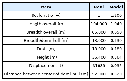
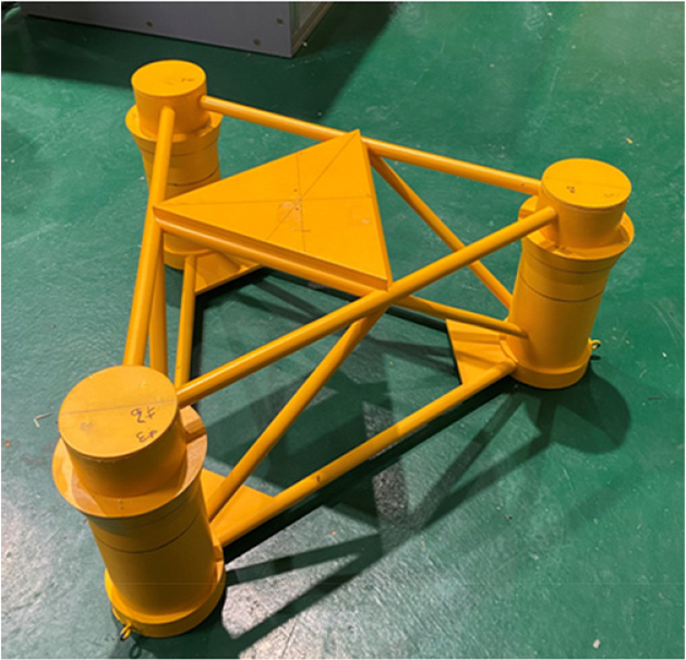
Semi-submersible and triangle platforms were used in the experiment. The model is fixed in the middle position of a square tank. During the experiment, the tension of the mooring lines is measured by an optical sensor and tension gauges. The model of the tension gauge used in this experiment was the WBST-100N gauge made by the Wonbang Company, which has a maximum capacity of 100 N. The principal dimensions of the semi-submersible and triangle platforms are listed in Tables 1 and 2, respectively. Figs. 4 and 5 show the real models of the semi-submersible and triangle platforms that were used in this experiment, respectively.
3.2 Optical Sensor Calibration
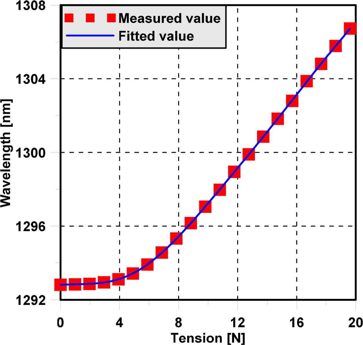
Since an optical sensor has several advantages compared to some conventional sensors, it was used to measure the mooring line tension of the semi-submersible and triangle platforms. A calibration test of the optical sensor was carried out first. Then, the relation between the wavelength from the optical sensor and tension was estimated. During the experiment, when ship motion occurs due to waves, the tension of the mooring lines changes. The variation of the wavelength of the optical sensor is recorded. The mooring dynamics in waves is estimated based on the measurement of the wavelength of the optical sensor. The setup for the optical sensor calibration is shown in Fig. 6. The relation between the wavelength and tension measured by the optical sensor is shown Fig. 7.
3.3 Experimental Setup
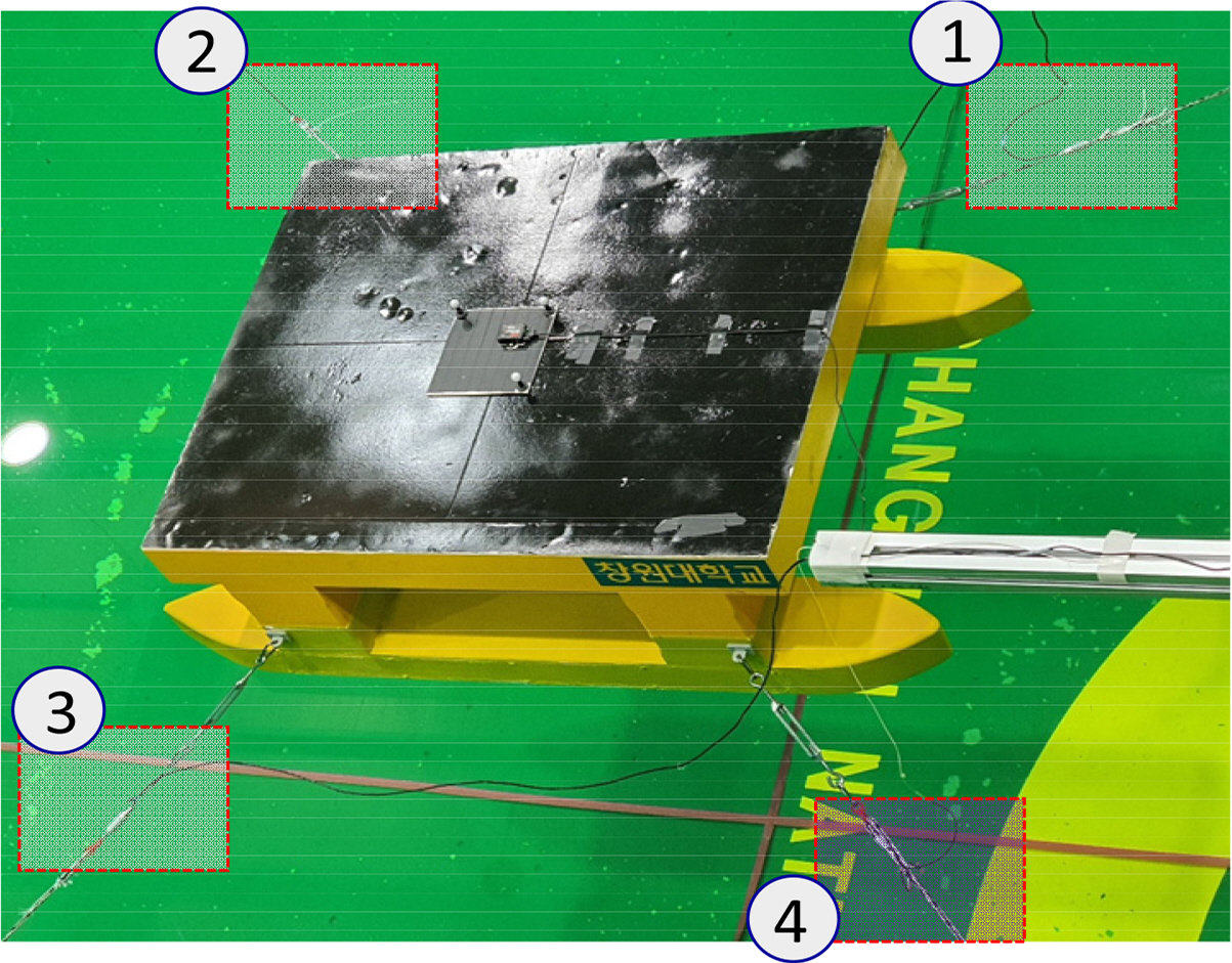
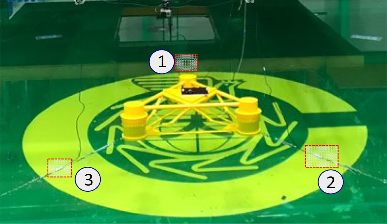
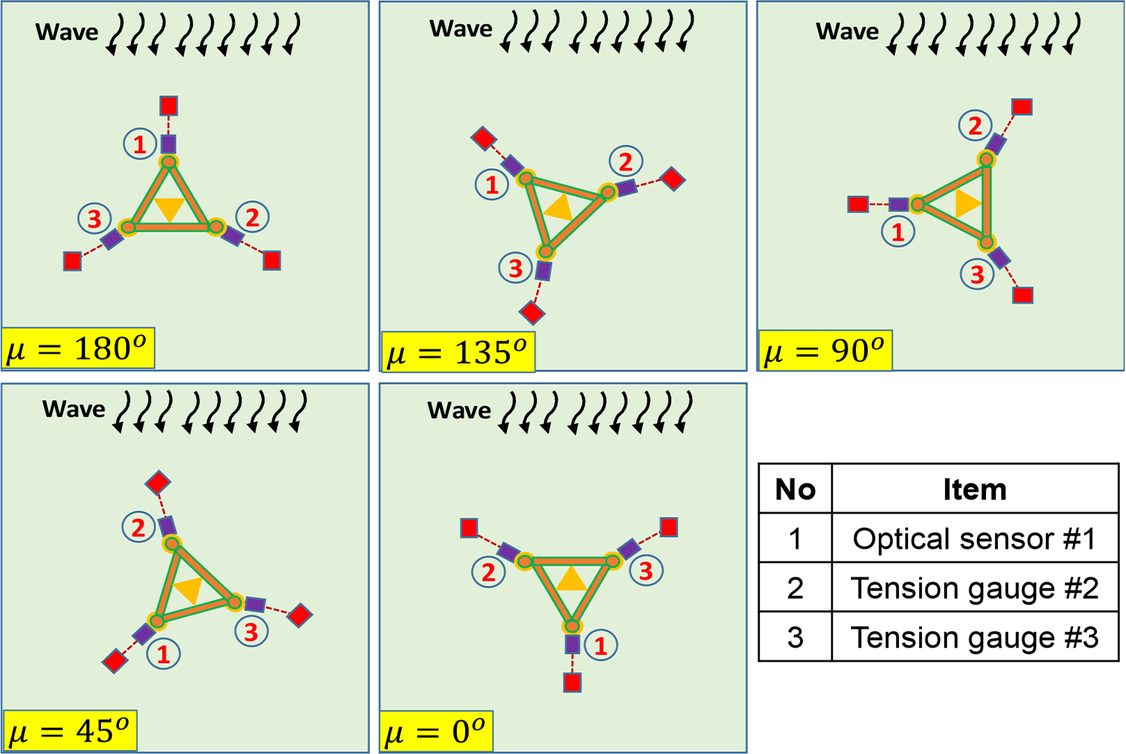
In the case of the semi-submersible, the model was attached to the tension gauges, optical sensor, and mooring line connect to a weight at the tank’s bottom. The tension of the mooring lines was measured by three tension gauges and an optical sensor. The angle between the mooring lines was 90 degrees. Fig. 8 shows the experimental setup of the semi-submersible. On the other hand, two tension gauges and an optical sensor were attached to the triangle platform. The angle between the mooring lines was 120 degrees. The experimental setup of the triangle platform is shown in Fig. 9. The position of the mooring line in various wave directions in the case of the semi-submersible and triangle platforms are shown in Figs. 10 and 11, respectively.
3.4 Data Analysis
During the experiment, the signal of the mooring line’s tension was recorded by the tension gauges and optical sensor. After each run, the data from tension gauges and optical sensor were checked in the time domain. Reruns were performed for the obvious error cases. The signal output from the tension gauge was converted from a voltage to the measured tension based on a calibration factor. The measured data from the tension gauges and optical fiber were analyzed using the maximum tension of the mooring lines in regular waves. In the case of irregular waves, the significant value of tension was estimated.
4. Result and Discussion
4.1 Performance of the Optical Sensor in Regular Waves
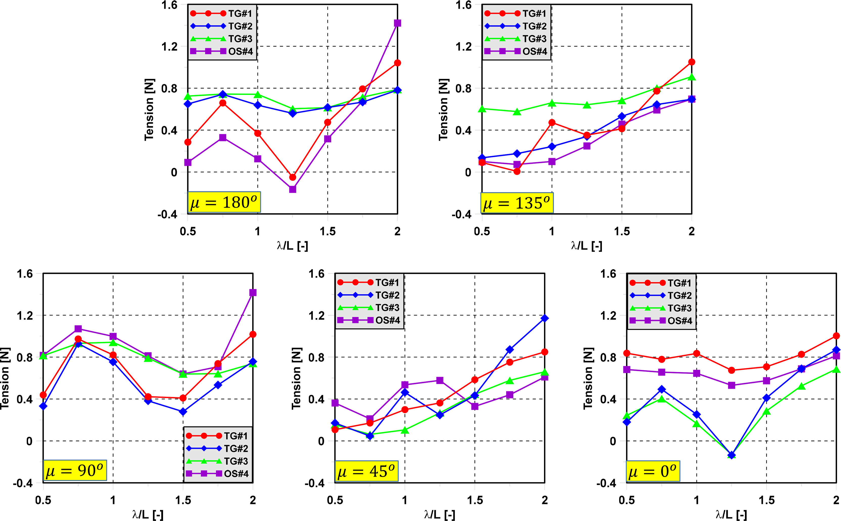
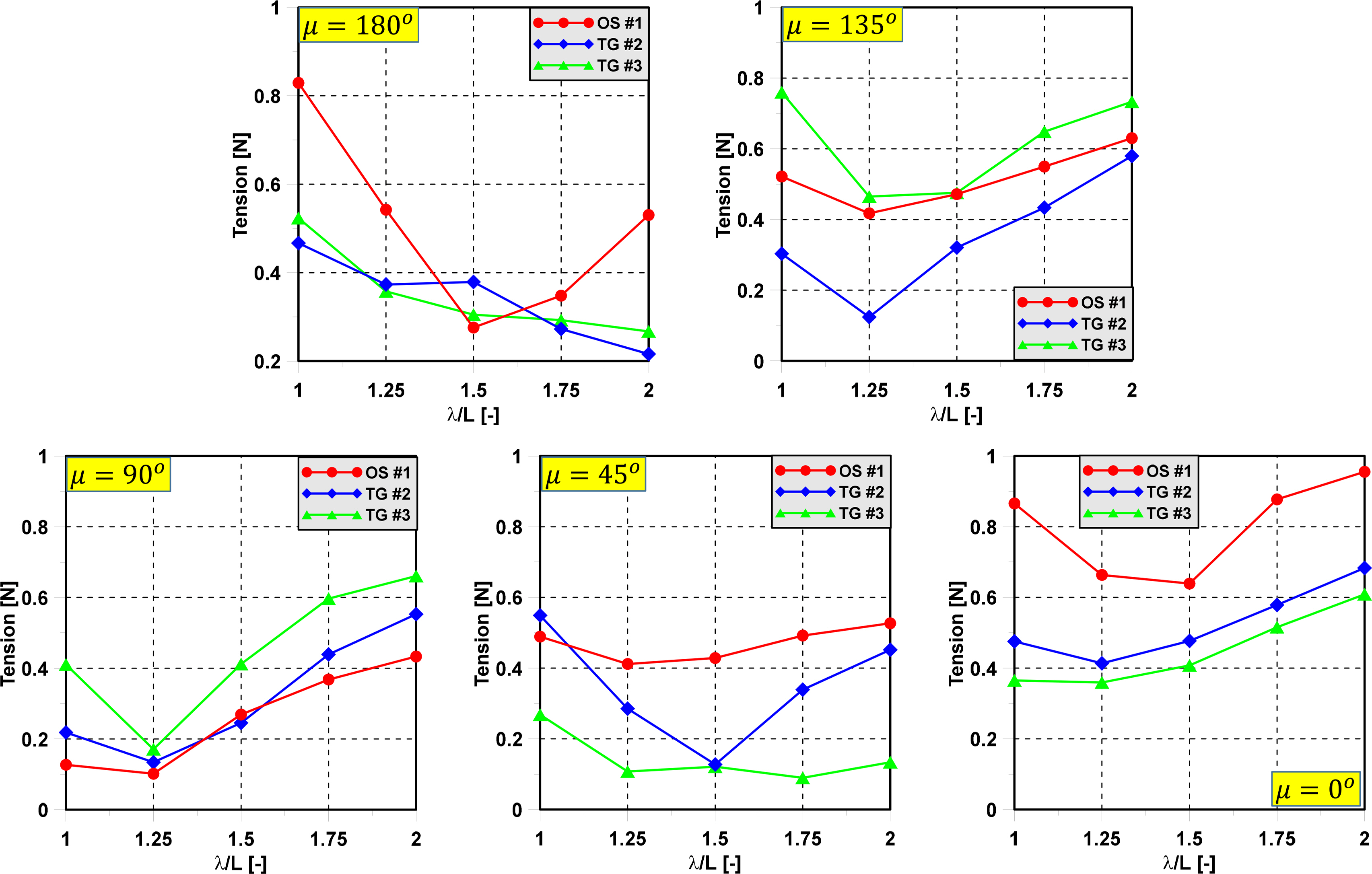
To investigate the effect of wave direction on the mooring dynamics, an experiment was carried out with regular waves and various wave directions. A model test was performed in regular waves to evaluate the tension of the mooring line of the semi-submersible and triangle platforms. Fig. 12 shows the maximum tension of mooring lines in various wave directions of the semi-submersible. The position of the mooring lines in the case of the semi-submersible when the wave direction changes are shown in Fig. 10. In head sea, the trend of tension gauge 1 (TG#1) and the optical sensor (OS#4) at the bow have almost the same trend. Tension gauge 2 (TG#2) and tension gauge 3 (TG#3) at the stern have a similar trend. In following sea, TG#1 and OS#4 change position for TG#2 and TG#3 in head sea. The trend of tension at the bow in head waves is the same as the tension at the bow in following sea. The maximum value of OS#4 has good agreement with TG#1 in head sea and following sea and with TG#3 in beam sea. Therefore, this proves the accuracy of the optical sensor in measuring the tension of the mooring line. In addition, the maximum tension of mooring lines occurs when the mooring lines are parallel to the wave propagation direction. Fig. 11 shows the position of the mooring lines in the case of the triangle platform when the wave direction changes. Fig. 13 shows the tension of the mooring lines in various wave directions and various wavelengths, where the wave direction has a dominant effect on the mooring dynamics. The maximum tension of mooring lines occurs when the mooring lines are parallel to the wave propagation direction. The tension of the mooring lines increases significantly at low frequency in all wave directions.
4.2 Performance of the Optical Sensor in Irregular Waves
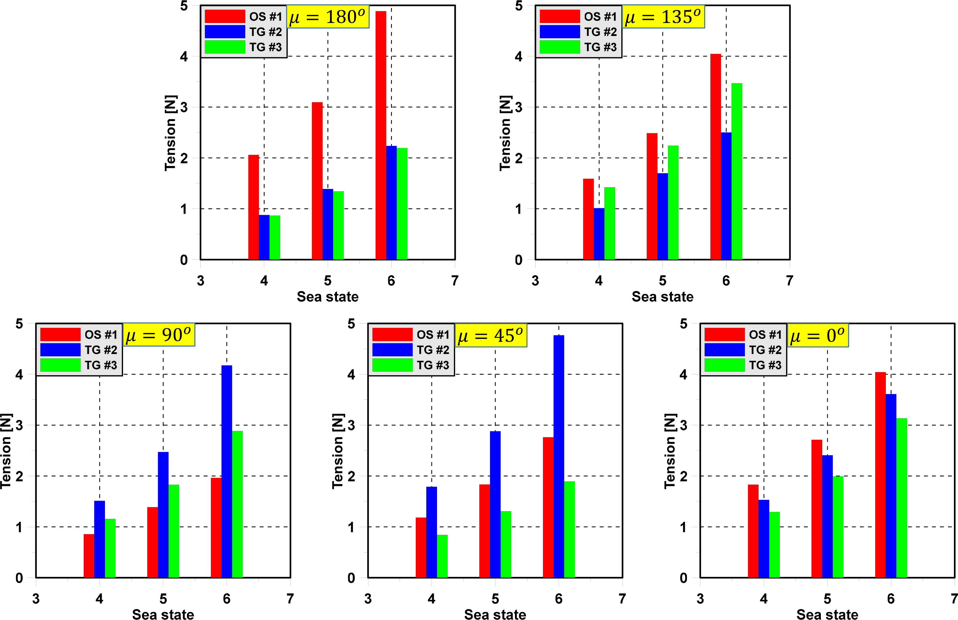
The significant value of the tension in irregular waves was considered in this study. The significant value of mooring tension was used to find the dominant value of tension that occurs. In addition, the significant value of tension is an important parameter for the statistical distribution of the mooring tension. This implies that the highest tension is not encountered too frequently. Moreover, when we know the significant value of tension, the range of tension can be determined. Fig. 14 shows the significant value of the mooring line’s tension of the semi-submersible in various wave directions.

Significant value of tension of mooring lines in case of semi-submersible in various wave directions
The significant value of OS#4 is slightly greater than that of TG#1 in head sea. In the following sea, the significant values of OS#4 and TG#1 have a significant difference. TG#1 is dominant when the wave direction approaches 135 degrees. At that time, the significant values of TG#2 and OS#4 are the same and the smallest. TG#2 is dominant when the wave direction approaches 45 degrees. In this case, the significant values of TG#1 and TG#3 are the same due to the symmetric nature of the model test. Fig. 15 shows the significant value of the mooring line’s tension of the triangle platform in various wave directions. The greatest significant value of mooring tension occurs when the mooring lines are parallel to the wave propagation direction. This happens because the wave direction has a direct effect on the motion response of the triangle platform. The extreme mooring tension depends on the type of sea state and wave direction.
5. Conclusion
In this study, experiments with semi-submersible and triangle platforms were carried out in the square wave tank at Changwon National University to investigate the tension of the mooring lines in various wave directions. An optical sensor was developed for estimating the tension of a mooring line. The concluding remarks are as follows.
First, the technical and operation details of the optical sensor were introduced. An optical sensor has several advantages in comparison with a conventional sensor due to light weight and small size.
Second, an experiment with a moored floating platform was performed to check the performance of the optical sensor. The optical sensor was effective in measuring the tension of the mooring lines.
Third, the maximum tension of the mooring lines was estimated to investigate the mooring dynamics due to the effect of the wave direction and wavelength in the regular waves. The maximum tension of mooring lines occurs when the mooring lines are parallel to the wave propagation direction. The tension of mooring lines increases significantly at low frequency in all wave directions.
Finally, the significant value of the mooring line’s tension in various wave directions was estimated in irregular waves. The greatest significant value of mooring tension occurred when the mooring lines were parallel to the wave propagation direction. This happened because the wave direction has a direct effect on the motion response of the semi-submersible and triangle platforms. The extreme mooring tension depends on the type of sea state and wave direction.
Notes
Hyeon Kyu Yoon serves as an editor of the Journal of Ocean Engineering and Technology but had no role in the decision to publish this article. No potential conflict of interest relevant to this article is reported.
This work was supported by the National Research Foundation of Korea (NRF) grant, which is funded by the Korean government (MSIT) (No. 2019R1F1A1057551).

