Changes in the Hydrodynamic Characteristics of Ships During Port Maneuvers
Article information
Abstract
To reach a port, a ship must pass through a shallow water zone where seabed effects alter the hydrodynamics acting on the ship. This study examined the maneuvering characteristics of an autonomous surface ship at 3-DOF (Degree of freedom) motion in deep water and shallow water based on the in-port speed of 1.54 m/s. The CFD (Computational fluid dynamics) method was used as a specialized tool in naval hydrodynamics based on the RANS (Reynolds-averaged Navier-Stoke) solver for maneuvering prediction. A virtual captive model test in CFD with various constrained motions, such as static drift, circular motion, and combined circular motion with drift, was performed to determine the hydrodynamic forces and moments of the ship. In addition, a model test was performed in a square tank for a static drift test in deep water to verify the accuracy of the CFD method by comparing the hydrodynamic forces and moments. The results showed changes in hydrodynamic forces and moments in deep and shallow water, with the latter increasing dramatically in very shallow water. The velocity fields demonstrated an increasing change in velocity as water became shallower. The least-squares method was applied to obtain the hydrodynamic coefficients by distinguishing a linear and non-linear model of the hydrodynamic force models. The course stability, maneuverability, and collision avoidance ability were evaluated from the estimated hydrodynamic coefficients. The hydrodynamic characteristics showed that the course stability improved in extremely shallow water. The maneuverability was satisfied with IMO (2002) except for extremely shallow water, and collision avoidance ability was a good performance in deep and shallow water.
1. Introduction
When a ship navigates in waters with varying depths, such as in-port, straits, and channel, it encounters danger from sinkage and trim, as well as changes in maneuvering characteristics. The interaction influences the behavior of ships in shallow water, and the flow velocity is increased by the gap between the ship bottom and the seabed. Furthermore, because of Bernoulli’s law, the pressure field in that area decreased, causing fluctuations in the hydrodynamic forces and moments, changing the attitude of ships, potentially resulting in unexpected collisions.
Research on the influence of shallow water has been conducted in recent years. Duarte et al. (2016) classified the water level in ship maneuvering based on the draft to water depth ratio (h/T) of a ship as deep water: h/T > 3.0; medium-deep water: 1.5 < h/T < 3.0; shallow water: 1.2 < h/T < 1.5; and extremely shallow water: h/T < 1.2. In addition, the authors provided some aspects affected by shallow water as resistance, trim, checking, counter tuning ability, turning diameter, and rate of turn. Jachowski (2008), Yun et al. (2014), and Lee (2021) examined the ship squat, also known as sinkage and trim in shallow water. Delefortrie et al. (2016) conducted the captive model test based on the 6-DOF (degree of freedom) maneuvering model of KVLCC2 (KRISO Very large crude oil carrier 2) at various under keel clearances of 20%, 30%, and 80%. In the study, the ship was forced in the horizontal 3-DOF with free heave and pitch motion, while the roll was estimated from the roll decay test. In addition, some assumptions and numerical analyses were applied to assess the ship in vertical motion. Taimuri et al. (2020) studied the 6-DOF maneuvering model in deep and shallow water. It started from horizontal 3-DOF and non-linear unified seakeeping. The maneuvering time-domain using a numerical decay test was introduced as a rapid method for estimating the heave, roll, and pitch motion. Carrica et al. (2016) used CFD (Computational fluid dynamics) and an experimental study to develop a direct method for zigzag maneuvers in shallow water (h/T = 1.2) for KCS (KRISO container ship). A satisfactory relationship between CFD and the experimental study was observed for self-propulsion results and zigzag variables except for the yaw and yaw rate. Lee and Hong (2017) examined the course stability in shallow water for very large vessels like KVLCC2 and DTC using CFD. The study confirmed that the course stability was improved in very shallow water and was more significant in KVLCC2.
Kim et al. (2007) used a mathematical model for a twin-propeller ship. They developed a 4-DOF mathematical model for a maneuvering simulation of a large container ship with a twin-propeller and twin-rudder, including roll motion effects by a model test and numerical simulation. According to the simulation results, the twin-propeller ship reported worse turning but better course-keeping and course-changing abilities than the single-propeller ship. Khanfir et al. (2011) presented a 3-DOF mathematical model for a twin-rudder system. A method based on free-running model test was proposed to estimate the rudder hull interaction coefficients. Di Mascio et al. (2011) used various prediction methods, namely statistical regression, system identification, and RANSE (Reynold-Averaged Navier-Stoke Equation), to estimate the maneuverability behavior of twin-propeller naval ships.
To address collision avoidance, Shaobo et al. (2020) proposed a new collision avoidance decision-marking system based on a modified velocity obstacle method designed for an autonomous ship. Lee et al. (2020) presented a collision avoidance method for multi-ship encounter situations. The round generating algorithm, which consisted of course changing and track keeping, was introduced to guide the ship to turn away from the obstacles and steer the ship back. Yim (2021) identified the effect of turning characteristics on collision avoidance for maritime autonomous surface ships. A method that could change the rudder angle and the ship speed was proposed to investigate the effect of turning ability on collision avoidance.
This study presented the maneuvering characteristics of an autonomous surface ship in deep and shallow water at low speed. A numerical simulation in CFD was used to estimate the hydrodynamic forces and moments by running the virtual captive model test. The accuracy of the numerical method was demonstrated by comparing the hydrodynamic forces and moments with the results obtained from the model test in the case of static drift test in deep water. The maneuvering characteristics as course stability and maneuvering simulation were then performed using the hydrodynamic coefficients obtained to evaluate the stability and maneuverability of the ship in deep and shallow water. A simple collision avoidance situation was also executed to investigate the effect of shallow water on the collision avoidance ability.
2. Maneuvering Simulation Model
2.1 Objective
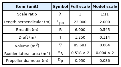
The candidate ship used in this study was an autonomous surface ship equipped with a twin rudder, twin propeller, and a skeg in the center of the stern. Fig. 1 shows a scale model of 1/11 attaching a twin-rudder and skeg used in the experimental study. Fig. 2 displays the boundary domain of a full-scale ship which consists of a bared hull and skeg, which is applied to numerical study in CFD. Table 1 lists the main particulars of the hull, propeller, and rudder. The propeller and rudder specifications were used in the maneuvering simulation.
2.2 Test Condition
The full-scale ship was assumed to operate at a low speed of 1.54 m/s in shallow water areas. The static drift, circular motion, and combined circular motion were simulated for a full-scale ship in deep and shallow water with water depth ratios of 2.0, 1.5, and 1.2, respectively, using a numerical simulation in CFD. Furthermore, an experiment of scale-model with the length between perpendiculars of 2.0 m was performed in a towing tank in deep water to verify the accuracy of numerical simulation. A corresponding 1.54 m/s in the speed of full-scale ship, the static drift test of model-scale was towed at 0.47 m/s. The numerical simulation in CFD was conducted under the constraints test listed in Table 2. All damping coefficients were obtained for deep and shallow water.
For this experimental study, the ship was towed by a carriage at a given speed. The hydrodynamic forces and moments were measured using two load cells located near the bow (LC#1) and stern (LC#2), where the distance to the midship was x1 and x2, respectively. Furthermore, all motions were restrained throughout the experimental performance. Fig. 3 presents an experimental installation of the ship.
For a numerical study, the virtual captive model test with the test condition in Table 2 was simulated using the Ansys fluent program to calculate the hydrodynamic forces and moments. In Table 2, and are the drift angle β and r′ dimensionless yaw rate, respectively.
The continuity and momentum were applied as governing assuming that the flow was incompressible (Mai et al., 2020). As an ITTC (International Towing Tank Conference) recommendation for CFD (ITTC, 2011), the boundary domain size was large enough to avoid backflow excluding the bottom side, and it was generated under shallow water conditions.
A hybrid mesh that includes the tetrahedral, hexahedral, and prism mesh type were adopted for mesh generation, as shown in Fig. 4. Table 3 lists the analytic method for the CFD simulation. The boundary conditions were set for each domain corresponding to its physical characteristics, such as the inlet assigns the pressure-inlet, the outlet sets the pressure-outlet, the top and sides are symmetry, the ship defines the no-slip wall, and the bottom specifies the no-slip wall to consider the influent of shallow water. The k − ω SST (Shear stress transport) turbulence model is applied extensively to predict the hydrodynamic forces and moments on a maneuvering ship because of several advantages in terms of its accuracy and time calculation (Quérard et al., 2008). The volume of fluid and open channel flow are the techniques to define the free surface and two flow phases of water and air. A SIMPLE (Semi-implicit method for pressure-linked equations) algorithm was used to solve the governing iteratively, adjusting the pressure to ensure that the resulting velocity field satisfied continuity. The least-squares cell-based method was used to evaluate the gradient of flow variables. The quantities at cell faces were calculated from the cell-centered values by the second-order upwind method. Unlike the static test, the circular motion test determines the rotating fluid zones using a multiple reference frame approach.
2.3 Mathematical Model
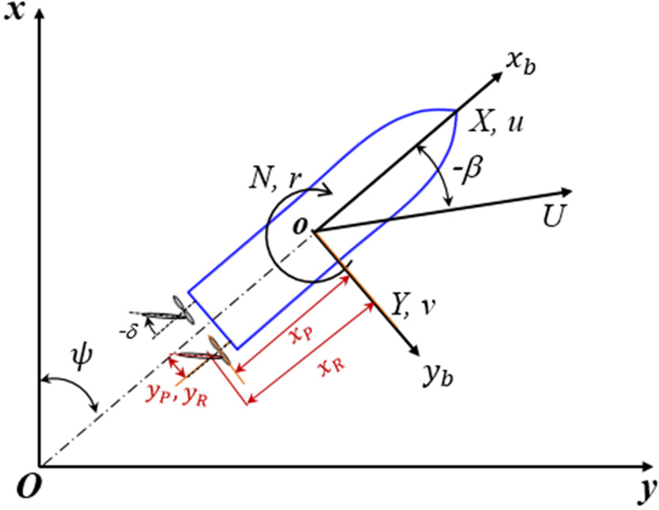
Two coordinate systems comprising earth-fixed coordinate (Oxy) and body-fixed (oxbyb) were set to determine the 3-DOF motion of the horizontal plane, as shown in Fig. 5. The earth-fixed coordinate defined the ship trajectory, orientation angle, and body-fixed (oxbyb) defined the of motion and external force acting on the ship. The origin of the ship was located at the intersection of the midship, centerline, and draft.
The maneuvering motion of 3-DOF in the horizontal plane was written for surge, sway, and yaw. Eq. (1) expresses the of motion of the ship based on the maneuvering modeling group (MMG) model (Yasukawa and Yoshimura, 2015). The external force on the right is the component of hull force, thrust, and rudder force, denoted by the letters H, P, and R.
The mathematical model of the hull force, thrust, and rudder force on the right side of Eq. (1) was formulated in Eqs. (2), (3), and (4), respectively, for twin-screw naval ship (Kim et al., 2021; Khanfir et al., 2011). The model of the hull forces Eq. (2) was determined as the regression formula of simulation results. In which the damping coefficients regarding sway velocity Xvv, Yv, Yv|v|, Nv, and Nv|v| were estimated from the static drift test where the sway velocity was generated, the damping coefficients with respect to the yaw angular velocity Xrr, Yr, Yr|r|, Nr, and Nr|r| were obtained from the circular motion test, where the yaw angular velocity was given, and the coupling damping coefficients relative to sway velocity and yaw rate Xvr, Yvvr, Yvrr, Nvvr, and Nvrr were taken from combined circular motion with drift, where both sway velocity and yaw angular velocity were generated. Furthermore, the added mass coefficients Xu̇, Yv̇, Yṙ, Nv̇, and Nṙ were determined from the pure surge, pure sway, and pure yaw test reported by Kim et al. (2021).
The parameters mentioned in the thrust model (3) and rudder model (4) are expressed below. The parameter in the formulae was written for the rudder and the propeller on the starboard side (subscript S), so the formulae of the port side could be obtained by replacing them with subscript P, and the formulae are the same except for the flow straightening coefficient (γR) and wake correction coefficient (CP). γR in the sway velocity (vR) formula of the rudder was different as
3. Analysis results
3.1 Verification
The modeling and simulation method in CFD was verified by comparing the results of the sway force and yaw moment of static drift test in the deepwater with the experimental results, as shown in Fig. 6. The simulation results matched well with the experimental method, particularly at slight drift angles (<±12°). The yaw moment differed slightly as the drift angle increased, and it was asymmetrical between the negative and positive drift angles. On the other hand, this did not affect maneuvering analysis because of the required linear coefficients. The comparison demonstrated the accuracy of the simulation method in estimating the hydrodynamic forces and moments on a maneuvering ship.
3.2 CFD Simulation Results
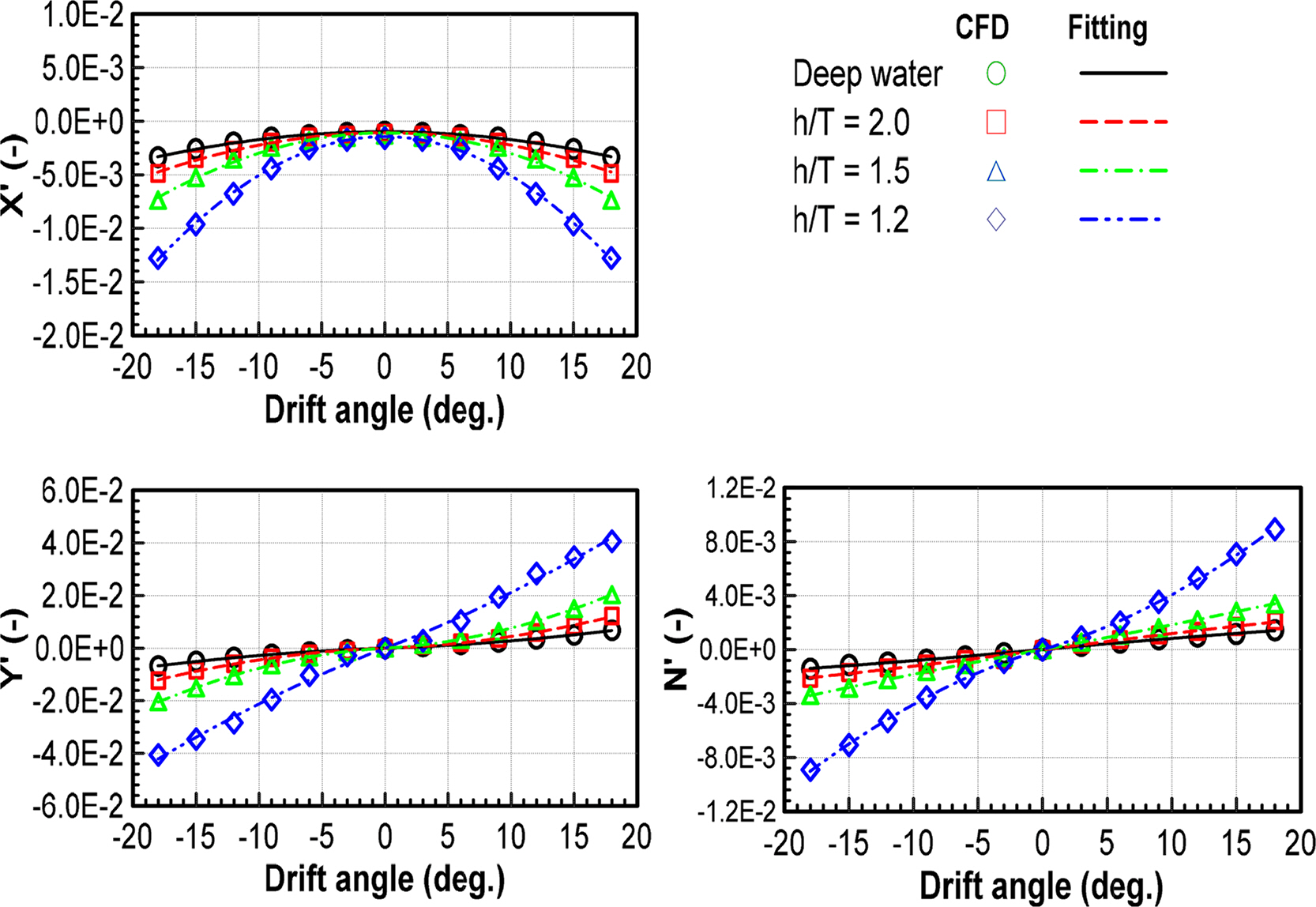
The static test was performed to estimate the damping coefficients versus the velocities and yaw rate of the surface ship; it was the static drift, circular motion, and combined circular motion with drift. Table 4 provides details of the hydrodynamic force model for each test. The hydrodynamic force model was divided into a linear model, where the linearity of the force was measured at small motion variables, and a non-linear model, where the non-linearity of the force was predicted at greater motion variables. Non-dimensionalization complies with the prime system of the Society of Naval Architects and Marine Engineers (SNAME), in which non-dimensional forces and moments were written as F′ = F/(0.5ρU2L2) and M′ = M/(0.5ρU2L3), respectively. This model was applied to the ship under deep and shallow water conditions. Fig. 7 presents the results of the static drift test at various water depths. The results were obtained by adjusting the drift angle by±18°. As the water depth became shallower, the hydrodynamic forces and moments were greater, particularly in extremely shallow water (h/T = 1.2). It increased two times compared to h/T = 1.5.
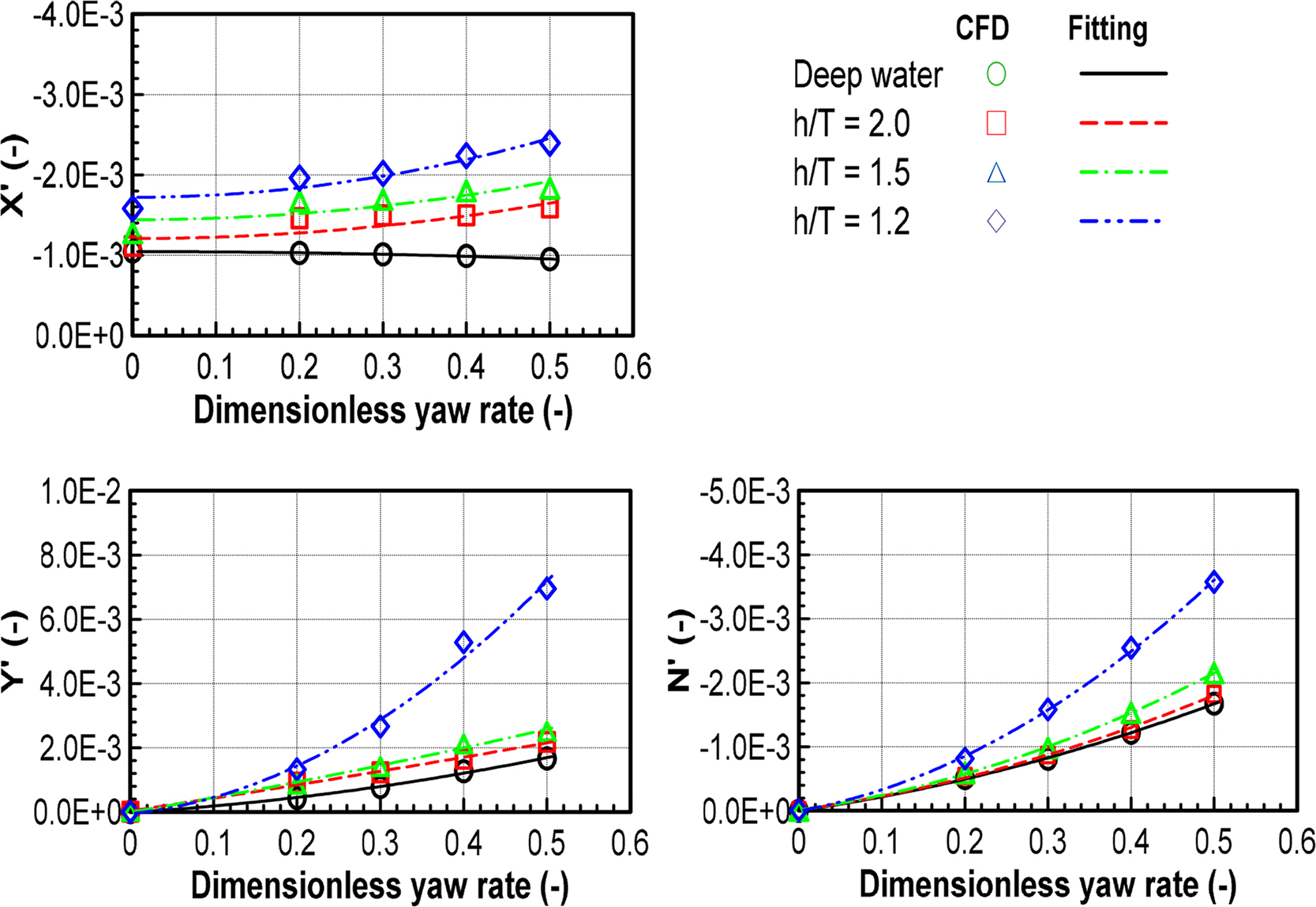
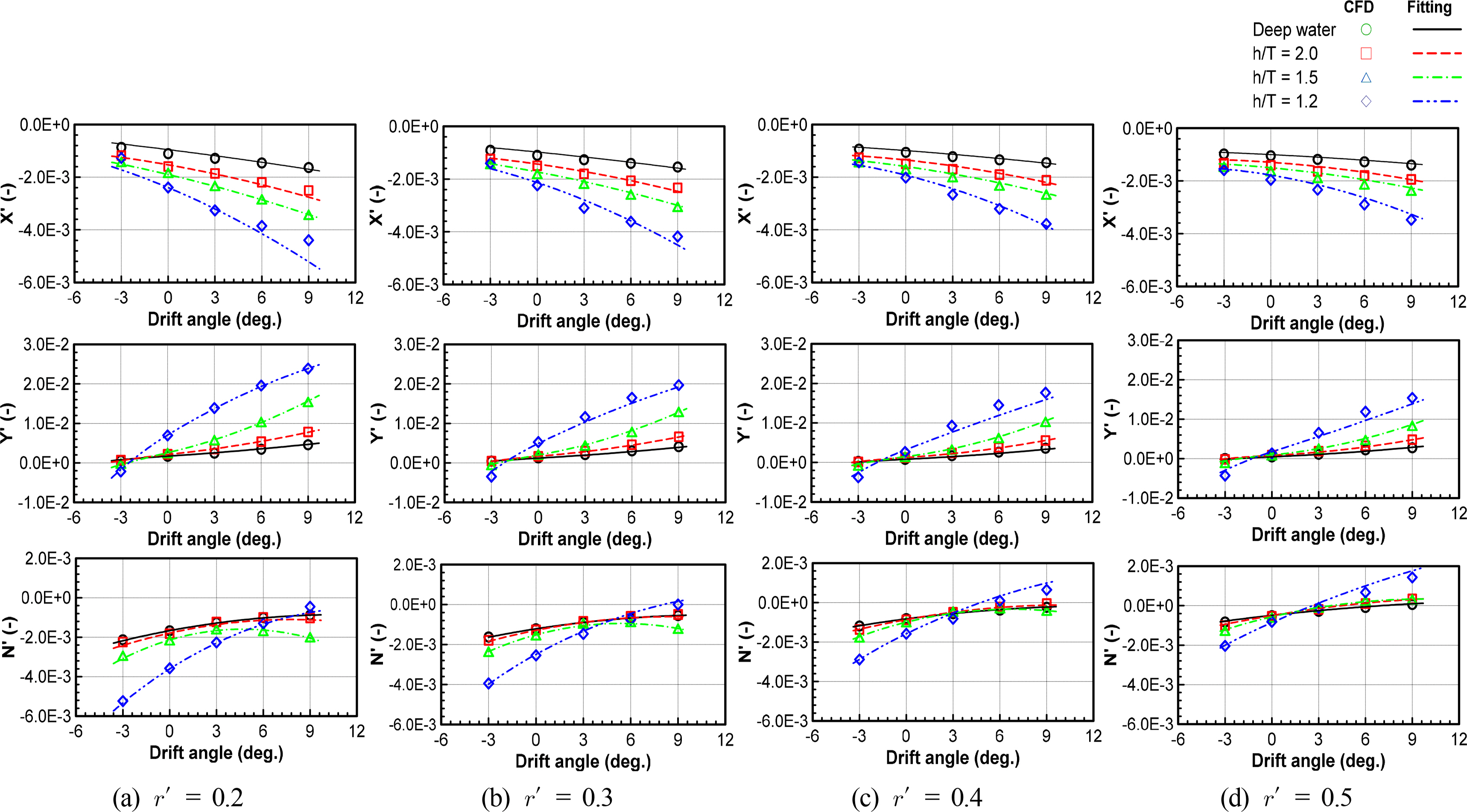
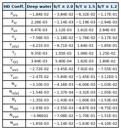
Similar to the static drift test, the hydrodynamic forces and moments in the circular motion test were obtained by changing the yaw angular velocities, as shown in Fig. 8. Fig. 9 shows the results of the combined circular motion with drift by varying drift angles and yaw angular velocities. The hydrodynamic forces and moments increased with decreasing water depth, and the drift angle and yaw angular velocity increased. The hydrodynamic forces and moments increased slightly from deep to medium shallow water but significantly increased in extremely shallow water. These results proved the influence of shallow water on the sway velocity and yaw rate. The increase in hydrodynamic forces and moments in shallow water was caused by an increase in flow velocity and a decrease in pressure through the gap between the ship bottom and the seabed. Fig. 10 shows the increase in flow velocity through the gap between the ship bottom and seabed as water depth becomes shallower. Table 5 lists the damping coefficients in deep and shallow water.
4. Dynamic Simulation
4.1 Course Stability
Stability analysis was performed to evaluate the course stability relative to the course of a ship. It was analyzed based on the linear hydrodynamic coefficients. As mentioned above, the linear coefficients were obtained by analyzing the hydrodynamic forces and moments at a small motion variable as the drift angle was smaller than 6° in the static drift test and the non-dimensional yaw angular velocity was less than 0.3 in the circular motion test. The course stability was examined as a function of the water depth using a sway-damping lever (l′v = N′v/Y′v ), yaw damping lever (l′r = N′r/(Y′r − m′)), and course stability index (C = N′r/(Y ′r − m′)−N′v/(Y′v)). The course was stable if the value of the course stability index was positive but was unstable if negative. Fig. 11 shows the results of the course stability based on the water depth. The sway damping lever decreased gradually while the yaw damping lever increased as the depth became shallower. In particular, a rapidly increasing yaw damping lever was observed in extremely shallow water (h/T = 1.2). The course stability index showed that it was unstable from deep water to h/T = 1.5 and improved in extremely shallow water. The yaw damping lever affected the course stability significantly.
4.2 Maneuverability Simulation
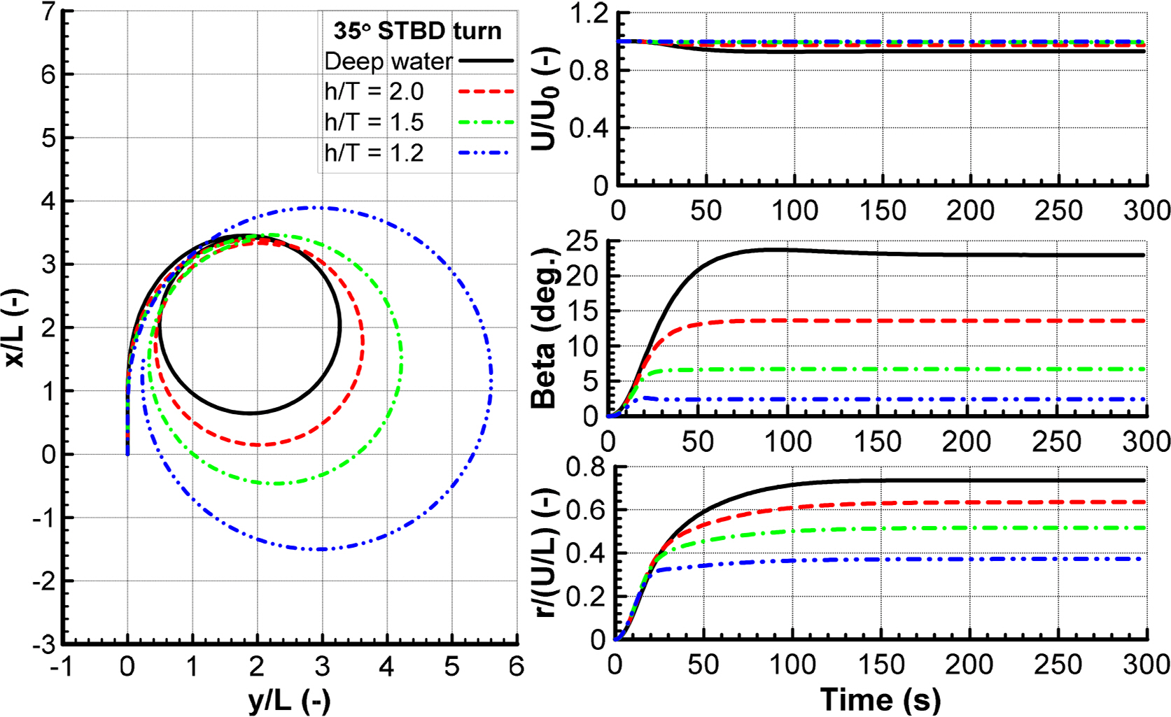
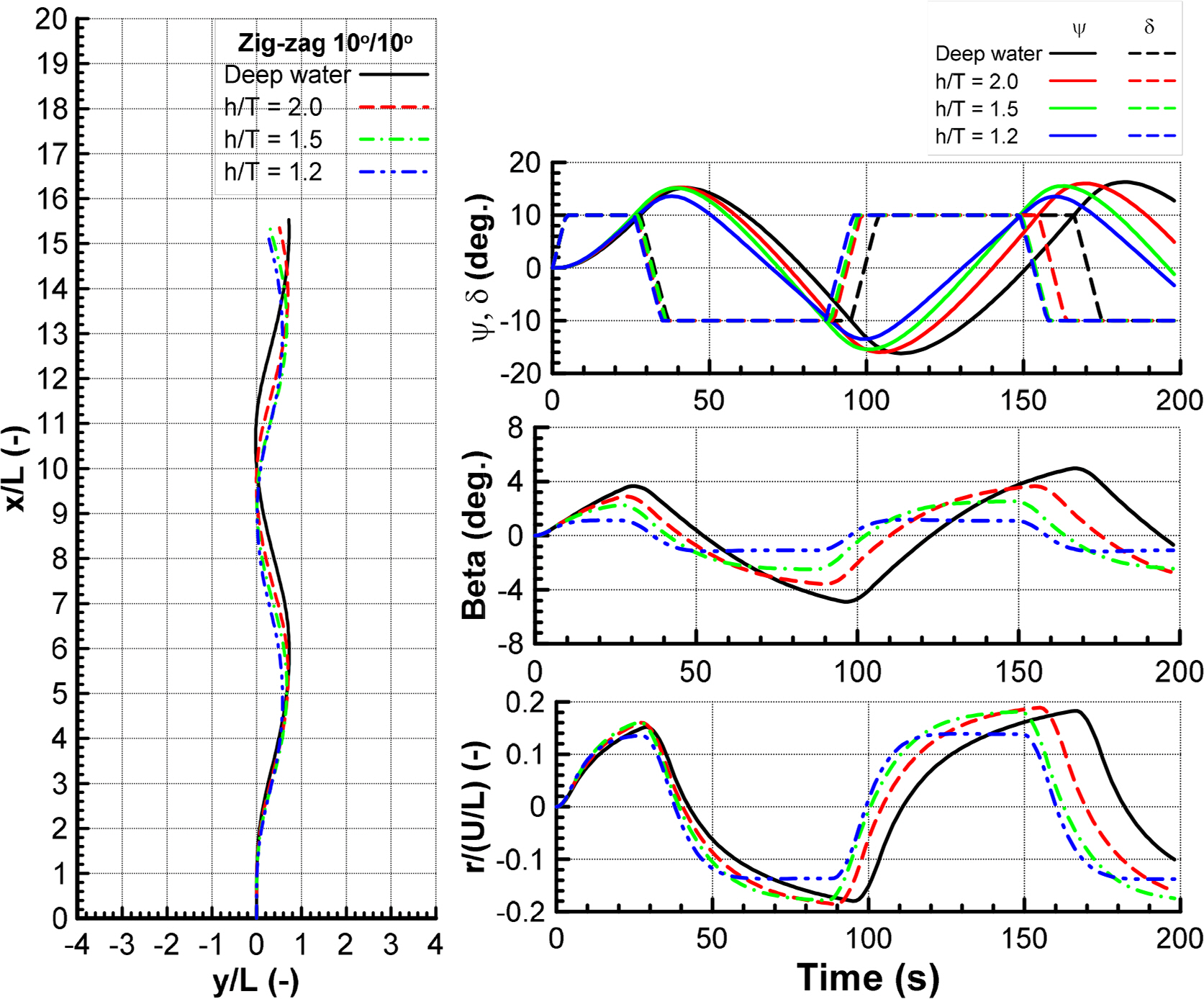
The maneuvering performance of the ship in shallow water was evaluated by simulating the turning circle 35° to the starboard side and zigzag 10°/10° test under an initial speed of 1.54 m/s. It was obtained by solving the 3-DOF of motion with the maneuvering coefficients, in which the damping coefficients were determined by the virtual captive model test, as shown in Table 5. The added mass coefficients were obtained from Kim et al. (2021), and the interaction coefficients of the rudder model and thrust model were taken from Kim et al. (2021). Figs. 12 and 13 present the results of turning circle and zigzag 10°/10° in the deep and shallow water. The turning circle was similar to the previous studies. The turning rate and drift angle were reduced, leading to a larger trajectory than that in deep water. This suggests that the influence of shallow water increased with decreasing water depth to h/T = 1.2. It was caused by the increasing hydrodynamic forces acting on the hull as the depth decreased. Therefore, the turning parameters in h/T = 1.2 did not satisfy the International Maritime Organization (IMO) (IMO, 2002). For the zigzag 10°/10° test, the first overshoot angle was more dominant at h/T = 1.5, 2.0, and smaller at h/T = 1.2 compared with those of deep water. By contrast, the second overshoot angle decreased gradually with increasing water depth to h/T = 1.2. Furthermore, the zigzag maneuver satisfied the IMO (2002) for deep and shallow waters.
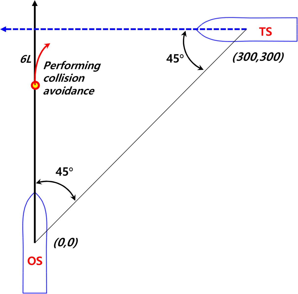
The ship collision avoidance was conducted to examine the effect of shallow water on the collision avoidance ability of the ship. The dynamic model was applied to the of motion for both the own ship (OS) and target ship (TS) to simulate the ship collision avoidance. A simple scenario based on the encounter situation of the cross-right according to the International Regulations for Preventing Collisions at Sea (COLREGs), was undertaken in this study, as shown in Fig. 14. Collision avoidance was implemented when the owner detected the trajectory of the target ship at a distance of 6L, as suggested by Fuji’s ellipse model based on the collision risk (Fuji and Tanaka., 1971). The rudder or propeller was then commanded to prevent the collision. In this case, the rudder of the own ship was turned 10° when it was a distance of 6L from the target ship. Fig. 15 shows the collision avoidance simulation in deep and shallow water at different times. The collision avoidance ability of the ship was expressed well in both deep and shallow water because the target ship could reach a safe area when the own ship touched the trajectory of the target ship. On the other hand, the ability to avoid collisions in shallow water appeared to be superior.
5. Concluding Remarks
This study examined the hydrodynamic characteristics of an autonomous surface ship throughout the port maneuvers.
A numerical study in CFD was used to perform the virtual captive model test to measure the hydrodynamic forces and moments in deep and shallow water. In addition, a model test for static drift test in deep water was also carried out to demonstrate the accuracy of the numerical study, and a good agreement was observed between the experimental and numerical study. The numerical results in shallow water confirmed that the hydrodynamic forces and moments increased as water depth became shallower because of the accelerating flow velocity through the gap between ship bottom and seabed. The maneuvering coefficients were determined by distinguishing a linear model from the non-linear model, in which the linear coefficients were achieved from small motion variables.
The hydrodynamic characteristics in deep and shallow water were analyzed by assessing the course stability, maneuvering simulation, and collision avoidance. The course stability was conducted using the linear coefficients. The sway-damping lever decreased gradually while the yaw-damping lever increased as the deep water became shallower, and the course stability improved in extremely shallow water. A maneuvering simulation was obtained by solving the 3-DOF of motion with the mathematical models of twin-propeller and twin rudder. This denoted a larger turning circle in shallow water due to increased hydrodynamic forces and moments. Moreover, the parameters of the turning test and zigzag 10°/10° in deep and shallow water were satisfied with the IMO (2002) except for the parameters of the turning test at h/T = 1.2. Furthermore, a simple collision avoidance of cross-right situation was executed to investigate the effect of shallow water on the collision avoidance ability. Shallow water looked better than deep water in the collision avoidance ability of the ship, even though the turning ability was better in deep water.
Nomenclature
O − xy
Earth-fixed coordinate
o− xbyb
Body-fixed coordinate
ψ
Heading angle
U
Ship speed
β
Drift angle
u
Surge velocity
v
Sway velocity
r
Yaw rate
u̇
Surge acceleration
v̇
Sway acceleration
ṙ
Angular acceleration
Izz
Yaw mass motion of inertia
xG
Longitudinal center of gravity
m
Ship mass
nP
Propeller revolution
t
Thrust deduction factor
xP
Longitudinal coordinate of propeller position
yP
Lateral coordinate of propeller position
wP
Wake coefficient in maneuvering motion
KT
Propeller thrust open water characteristic
JP
Propeller advanced ratio
tR
Steering resistance deduction factor
aH
Rudder increase factor
xH
Longitudinal coordinate of the rudder position
FN
Rudder normal force
UR
Resultant rudder inflow velocity
αR
Effective inflow angle to the rudder
uR
Longitudinal inflow velocity
vR
Lateral inflow velocity
fα
Rudder lift gradient coefficient
Λ
Rudder aspect ratio
ε
Ratio of a wake fraction at propeller and rudder positionsAn experimental constant for expressing uR
κ
Ratio of propeller diameter to rudder span
η
Flow straightening coefficient
γRβR
Effective inflow angle to the rudder in maneuvering motions
CP
Wake correction coefficient
βP
Geometrical inflow angle the to propeller in maneuvering motions
C
Course stability index
l′r
Yaw damping lever
l′v
Sway damping lever
Acknowledgements
This research was supported by Changwon National University in 2021–2022.
Notes
Hyeon Kyu Yoon serves as an editor of the Journal of Ocean Engineering and Technology, but has no role in the decision to publish this article. No potential conflict of interest relevant to this article was reported.


