Numerical Investigation of Multi-body Wave Energy Converters’ Configuration
Article information
Abstract
We investigate the performance of multi-body wave energy converters (WECs). This investigation considers multiple scattering of water waves by the buoys of a WEC under the generalized mode approach. Predominantly, the effect of a WEC’s configuration on its energy extraction is studied in this research. First, single-row terminator and single-column attenuator arrays of vertical cylinders have been studied. The performance of these attenuator arrays shows that the wall effect induced by the periodic buoys influences the wave propagation and energy extraction in these WECs. Further studies show that a single-row terminator array of vertical cylinders performs better than the corresponding single-column attenuator array. Subsequently, multi-row terminator arrays of vertical cylinders are investigated by conducting a parametric study. This parametric study shows that the hydrodynamic property of three resonance phenomena makes energy extraction efficiency drop down, and the magnitude of energy extracted oscillates between the resonance points in these WECs. Finally, a 4×8 terminator array of vertical cylinders is studied to determine the effect of various dx (x-directional distance between adjacent rows) within this WEC on its performance. In particular, this study enforces at least two equal dx values within the 4×8 terminator array of vertical cylinders. It shows that a small value of this dx leads to better energy extraction efficiency in some of these various dx arrays than that of a corresponding regular array with the same dx.
1. Introduction
Renewable energy research is given the utmost importance worldwide to overcome the striking threat to the environment from non-renewable energy sources due to their conversion. In particular, energy generation using the aspects of the oceans has a huge potential as oceans are renewable sources of energy in abundance. Relatedly, wave energy converters (WECs) convert the kinematic energy of water waves into a usable form of energy. So, WECs have been researched under naval architecture and ocean engineering for a long time. WECs are of three types: oscillating body, overtopping, and oscillating water column WECs. In particular, oscillating body WECs use a buoy’s kinematic energy resulting from the water wave-body interaction and convert it into electric energy using a power take-off (PTO) device. Generally, an oscillating body WEC has several buoys. Moreover, the following oscillating body WECs result from the relative orientation between their buoys and water waves (Mei et al., 2005): terminator, attenuator, and omnidirectional oscillating body WECs. For example, the buoys of a terminator type oscillating body WEC are arranged perpendicular to the water wave direction. On the other hand, the buoys of an attenuator type oscillating body WEC are arranged along the water wave direction. Finally, an omnidirectional type oscillating body WEC performs identically for all arrangements of its buoys with respect to the water wave direction.
Several research activities have been carried out worldwide on oscillating body WECs to improve their energy conversion. Generally, it is better to use several smaller buoys instead of a larger single buoy in them (e.g., Garnaud and Mei, 2009). The oscillating body WECs with several buoys are shortly called multi-body WECs. However, the beneficial arrangement of buoys within multi-body WECs is unknown because it is hard to implement the multiple scattering of water waves by the buoys of the WECs in the analysis to find this arrangement.
Several theories have been proposed on the interaction between water waves and the buoys of multi-body WECs. Usually, a point absorber assumption is made in such theories in the long-wave region. In general, this assumption considers the incident and radiated water waves but not the diffracted water waves from the bodies (e.g., Falnes and Budal, 1982). On the other hand, a plane wave approximation considers the multiple scattering of water waves by the buoys in a multi-body WEC (Simon, 1982). However, this approximation cannot be used for an array of buoys in a multi-body WEC provided that the distance between buoys is close. So, an approximation suggested by McIver and Evans (1984) for vertical cylinders by correcting diffracted water wave components can be used in such situations. Notably, the multiple scattering of water waves by the buoys was studied by Kagemoto and Yue (1986) exactly. Their new multi-body hydrodynamic interaction theory used linear algebra of velocity potentials. In particular, they applied a characteristic matrix to the diffraction potential of the bodies by considering a generalized incident-wave potential for multi-bodies. Subsequently, another exact method for analyzing the interaction of water waves with vertical cylinders was proposed by Linton and Evans (1990) based on eigenfunction expansion. Later, increased computational capabilities led to a generalized mode approach to study multi-body interactions using the boundary element method (Newman, 1994). In particular, Newman (1994) demonstrated the applications of the generalized mode approach in studies other than multi-body interactions, such as hydroelasticity, hinge mode analysis, etc., as well. He also established a generalized boundary value problem and a generalized equation of the hydrodynamic forces in this approach. The exact methods of Kagemoto and Yue (1986) and Linton and Evans (1990) and the generalized mode approach of Newman (1994) are considered complete in analyzing the multiple scattering of water waves by the buoys under linear potential theory without special constraints. Meanwhile, these analyses become cumbersome under any numerical method when hundreds of buoys are used. Hence, Kashiwagi (2000) extended the theory of Kagemoto and Yue (1986) using a hierarchical ordering among a huge number of hydrodynamically interacting bodies and developed a new multi-body hydrodynamic interaction theory. Likewise, Tokić and Yue (2019) analyzed the multiple scattering of water waves by a large number of buoys recently. They found the hydrodynamic properties such as Bragg, Rayleigh, and Laue resonances and the existence of Rayleigh-Bloch waves in a periodic array of WECs.
This study is motivated by the research of Tokić and Yue (2019) and analyzes the effect of a multi-body WEC’s configuration on its energy extraction. We use the generalized mode approach and study the multiple scattering of water waves by the buoys (vertical cylinders) of different WECs. In addition, a parametric study has been conducted on the terminator and attenuator arrays of vertical cylinders in the absence of oblique waves.
2. Formulation
2.1 Equation of Motion of Buoys in a WEC
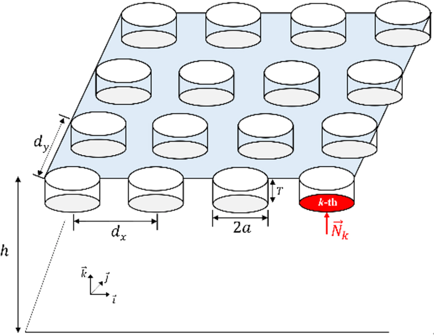
This study uses the generalized mode approach of Choi (2011) to consider the multiple scattering of water waves by the buoys of a multi-body WEC. In ideal fluid assumption, hydrodynamic pressure could be obtained from the velocity potential. The velocity potentials under this multiple scattering can be obtained using a boundary integral equation. However, the surface of each buoy should be discretized, and the normal vector components of the buoys’ surface should be defined to calculate the velocity potential. The schematic of a multi-body WEC used in this analysis is shown in Fig. 1. First, the velocity potential is defined in the following form:
The added mass (akj) and the damping coefficient (bkj) of the k-th buoy for the j-th mode of motion can be obtained for the generalized mode by integrating the product of the radiation velocity potential for the j-th mode of motion and the generalized directional cosine of the k-th buoy. Similarly, the unit water wave exciting force (Xk) is calculated by integrating the product of the diffraction velocity potential and the generalized directional cosine of the k-th buoy (Newman, 1994). Exactly,
2.2 Energy Extraction of the WEC
Generally, the time-mean extracted power of the WEC from the waves, P̄, is written in the following form.
In addition, the calculation of energy extraction efficiency of the WEC needs the capture width defined in the following form:
In addition, the efficiency of a multi-body WEC’s configuration can be found using the concept of array gain (Tokić and Yue, 2019) as follows:
2.3 Resonance in Multi-Body WECs
This research investigates the energy extraction efficiency of multi- body WECs under the hydrodynamic properties of them reported by Tokić and Yue (2019). In particular, three resonance phenomena in the array of buoys of multi-body WECs are considered in this study. These resonance phenomena are explained below.
2.3.1 Rayleigh resonance
Falnes and Budal (1982) investigated the water wave power extraction and radiated water wave from a terminator array of buoys demonstrated in Fig. 2 under point absorber assumption. The radiated water waves from this terminator array of buoys can be studied under the point absorber assumption by considering the periodicity of the velocity potentials. Consequently, the wave heading angle between the incident and the respective transmitted and reflected water waves from this terminator array of buoys have the following relation:

A terminator array of buoys and the radiated water wave from it (Falnes and Budal, 1982)
Subsequently, Eq. (13) becomes the following when there are no oblique waves.
So, the wave energy is redistributed equivalently at this frequency, resulting in abrupt changes in the energy extraction. This phenomenon is called Rayleigh resonance and causes loss of the buoys’ energy extraction, especially in this terminator array of buoys (Tokić and Yue, 2019).
2.3.2 Bragg resonance
Bragg resonance is a phenomenon causing strong reflection of water waves when they pass through periodic bodies or over bottom ripples (e.g., Liu and Yue, 1998; Alam et al., 2009). Water waves passing through periodic bodies are apparently reflected when the distance between the centers of two adjacent bodies is half of the wavelength of the water wave. Hence, the condition for Bragg resonance is:
Subsequently, the following equation is obtained when there are no oblique waves.
Generally, Bragg resonance causes abrupt loss of the buoys’ wave energy extraction due to the strong reflection of the incident water waves occurring during it.
2.3.3 Laue resonance
The effect of Laue resonance on the energy extraction of periodic WECs was first studied by Tokić and Yue (2019). Generally, the condition for Laue resonance in an array of buoys is:
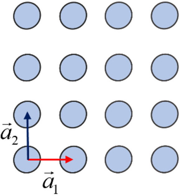
Particularly, the x-directional lattice vector of the rectangular array of buoys shown in Fig. 3 is a⃗1 = dxî. Then, Eq. (17) corresponding to this rectangular array of buoys is:
Equation (18) implies that Bragg resonance is a special case of Laue resonance when θm = π − θI. Finally, substituting Eq. (14) into Eq. (18) results in the following equation for the normal incidence of water waves onto this rectangular array of buoys.
This equation is quadratic in kdy or kdx at each (m, n) pair. Notably, Tokić and Yue (2019) reported a substantial reduction in the wave energy extraction of periodic WECs due to Laue resonance.
3. Numerical Investigation of the WECs’ Configuration
3.1 Vertical Cylinder
We consider vertical cylinders that have only the heave motion caused by their interaction with the water waves in the numerical analysis. Relatedly, the hydrodynamic properties of a vertical cylinder are well studied. For instance, the natural frequency of its heave motion due to the hydrodynamic forces is proportional to
3.2 Single-column Attenuator Array
First, we compute the non-dimensional average capture width (kW) of a single-column attenuator array, i.e., θI=0°, shown in Fig. 5. The total non-dimensional capture width of buoys is divided by the number of buoys to obtain this array’s non-dimensional average capture width. Three values for the x-directional distance between adjacent cylinders (dx) are considered in this analysis: 3a, 8a, and 14a. The results of this analysis are shown in Fig. 6. In particular, the upper graphs of this figure show that the energy extraction by this array decreases abruptly near the Bragg resonance frequency, and this abrupt decrease is denoted by a red dotted line in these graphs. This effect is especially large when Nx is not small enough. In addition, this resonance effect is small in the low-frequency region, as seen from the rightmost one of these graphs. Finally, the non-dimensional average capture width of a single-column attenuator array is small compared to that of a single buoy. This reduction is large as the number of buoy increases.
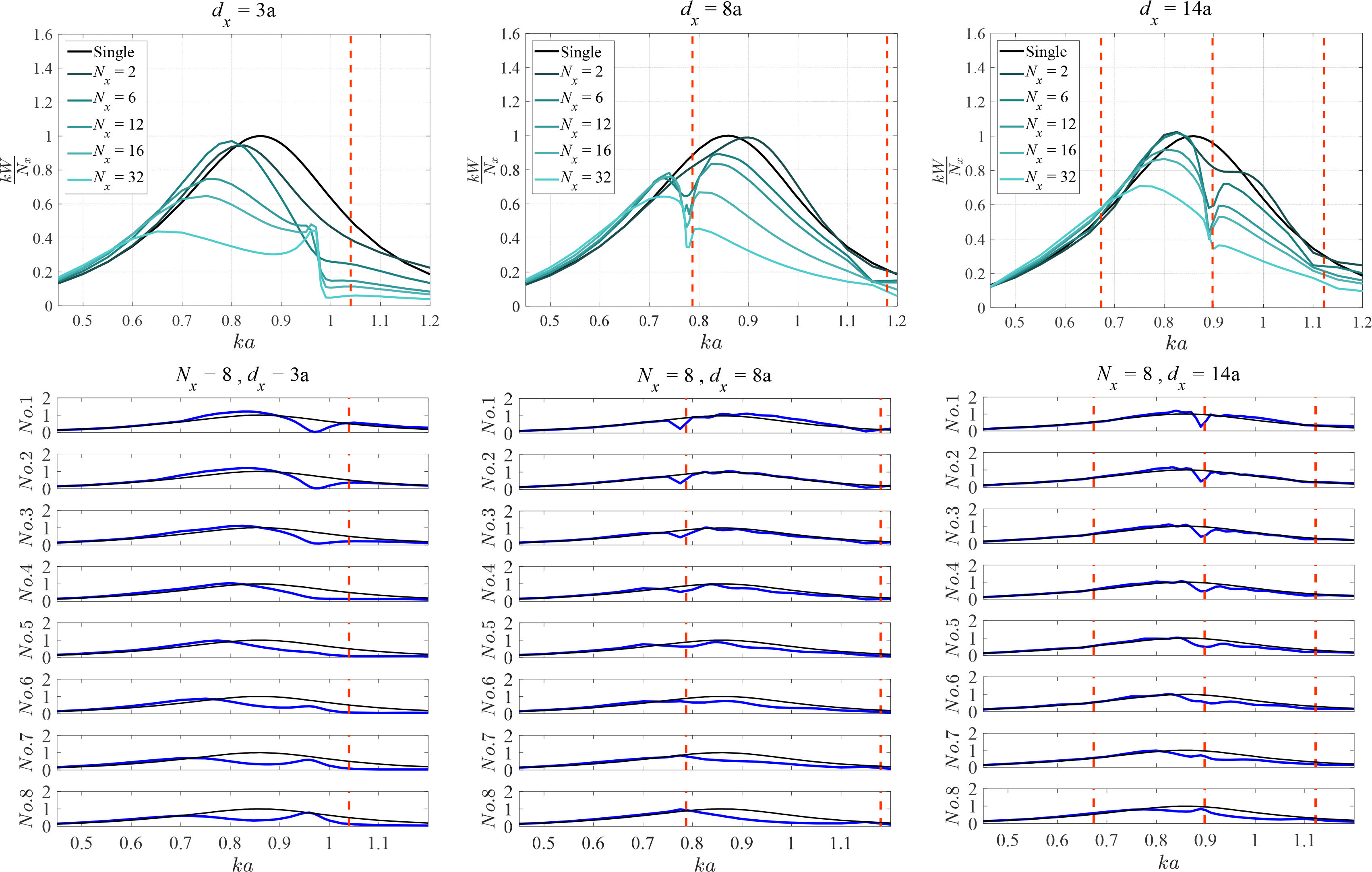
Non-dimensional capture width of a single-column attenuator array of vertical cylinders (Upper graphs: the average across all the buoys, Lower graphs: for each buoy in this array, and black lines: for an isolated buoy)
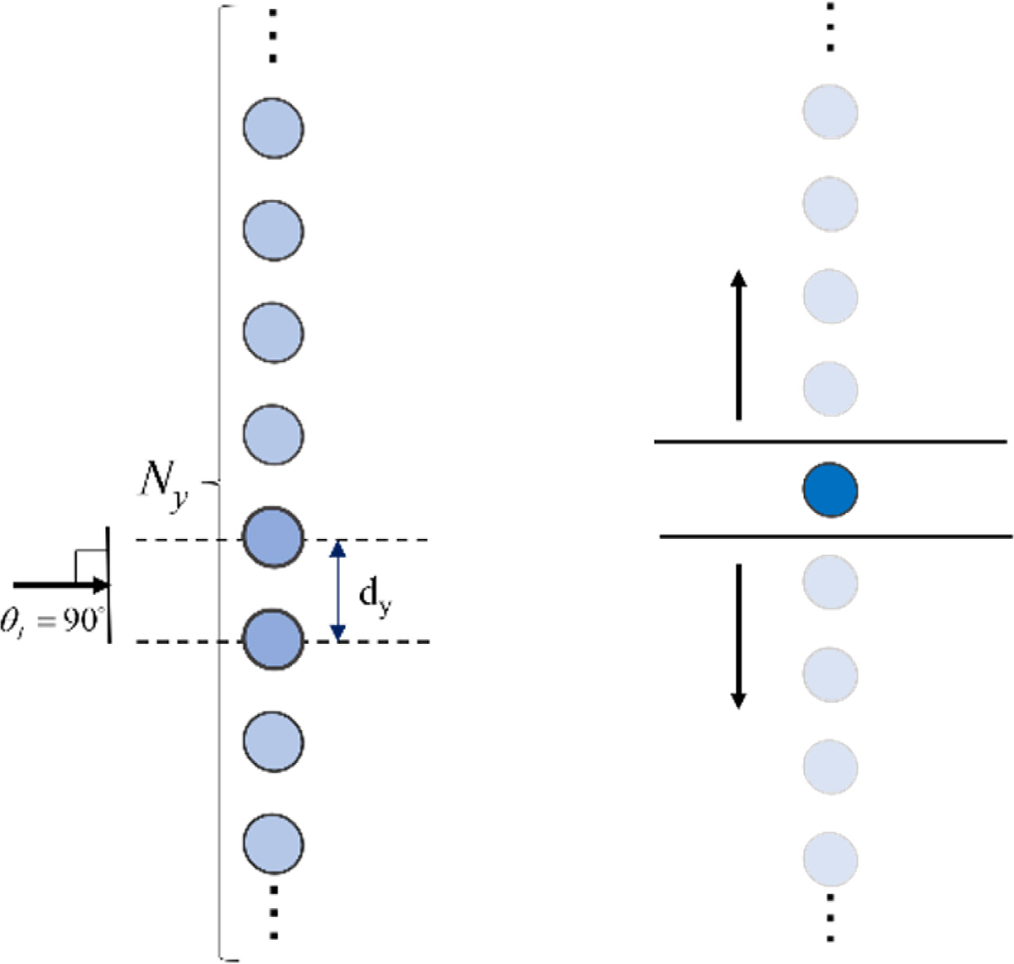
The lower graphs of Fig. 6 show the non-dimensional capture width of each buoy in the single-column attenuator array of vertical cylinders. The first 2 or 3 buoys achieve a large energy extraction, whereas the other buoys achieve a relatively small energy extraction except at the Bragg resonance region. This difference between the energy extractions of buoys is because the periodic buoy works like a wall, as demonstrated in the right side of Fig. 5. The water waves undergo a large reflection at the first few buoys due to the periodic buoys’ wall effect, which is concentrated at the first few buoys. It is also confirmed that there is a large reduction in the energy extraction of the first few buoys near the Bragg resonance frequency. Since buoys located at the trailing end of this array have low efficiency, this array’s non-dimensional average capture width decreases as the number of buoys increases in it.
3.3 Single-Row Terminator Array
Next, we compute the non-dimensional average capture width (kW) of a single-row terminator array of vertical cylinders shown in the left side of Fig. 7 by following a procedure similar to the one followed for the corresponding single-column attenuator array. Three values for the y-directional distance between adjacent cylinders (dy) are considered in this analysis: 3a, 8a, and 14a. The results of this analysis are shown in Fig. 8. Overall, the single-row terminator array of vertical cylinders works constructively. In particular, the energy extraction efficiency increases as the number of buoys increases, and then it converges for some number of buoys. However, energy extraction abruptly drops down near the Rayleigh resonance region, and this abrupt drop is denoted by a blue dotted line in the graphs of Fig. 8. Subsequently, this energy extraction becomes almost zero due to the emergence of new radiated water waves (Srokosz, 1980). The lower graphs of Fig. 8 show the non-dimensional capture width of each buoy in this array. These graphs indicate that each of these buoys achieves large energy extraction. In particular, the buoy in the middle of this array achieves high efficiency near the Rayleigh resonance frequency but not exactly at that frequency. Relatedly, the direction of constructive waves in this terminator array becomes the same as the array direction, i.e., |sinθm|= 1, during Rayleigh resonance. So, the wall effect of periodic buoys resulting when the constructive wave direction becomes the same as that of the array causes the water waves to concentrate between buoys due to the large reflection of them.
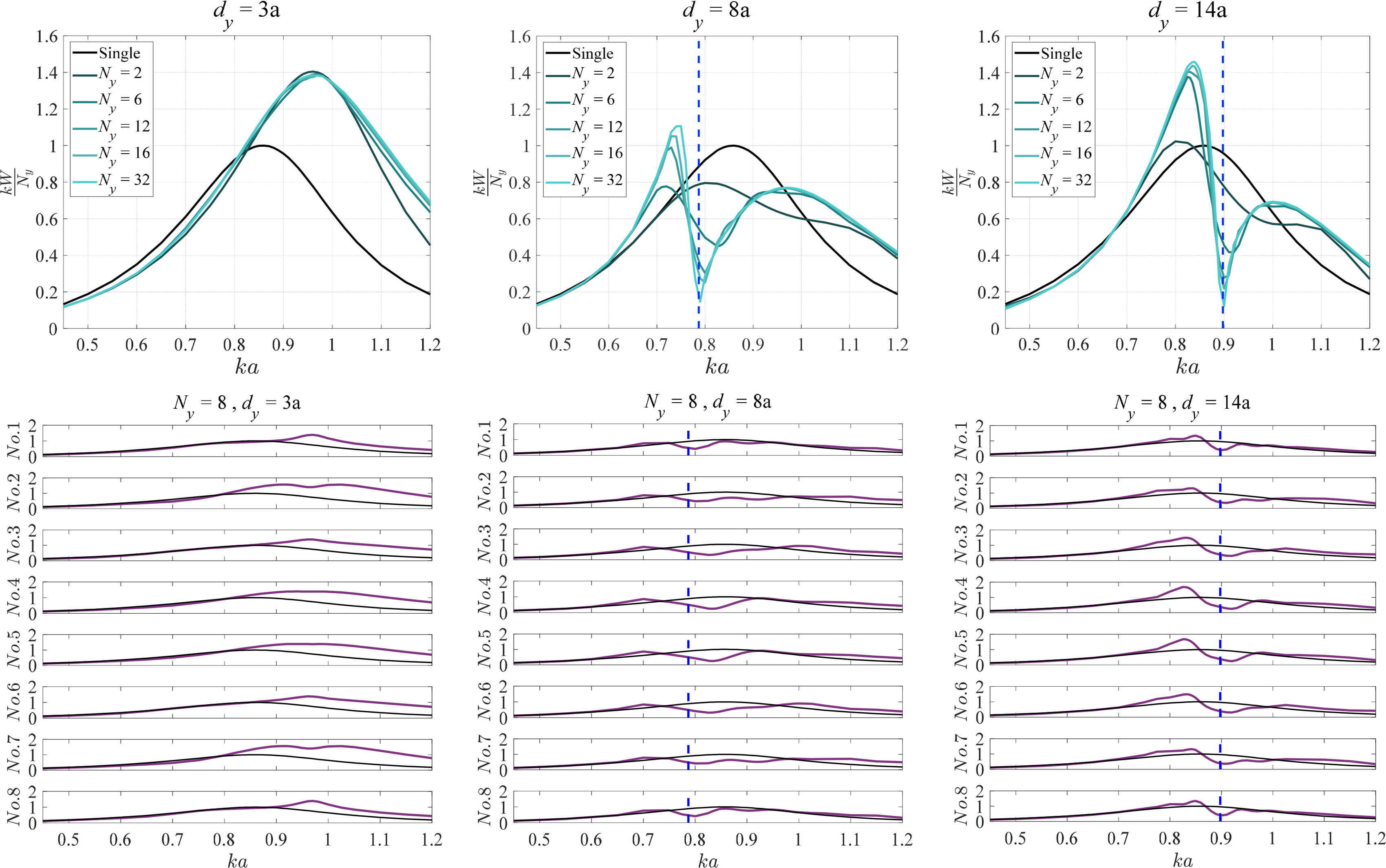
Non-dimensional capture width of a single-row terminator array of vertical cylinders (Upper graphs: the average across all the buoys, Lower graphs: for each buoy in this array, and black lines: for an isolated buoy). There is no Rayleigh resonance in 0.4–1.2 ka when dy = 3a.
Figs. 5–8 indicate that the wall effect induced by the periodic buoys changes the energy extraction efficiency. So, Kim and Cho (2019) used this correlation in WECs to improve their performance. In particular, they created lateral and back-side walls near only a few buoys. Hence, the lateral wall makes the buoys be in a terminator array, and the back-side wall makes buoys be similar to the first few buoys in an attenuator array, increasing the energy extraction efficiency.
3.4. Multi-row Terminator Array
The results of our analysis conducted so far indicate that the single-row terminator array of vertical cylinders shows a better energy extraction efficiency than that of the corresponding single-column attenuator array when the number of buoys is sufficiently large. Subsequently, we increase the number of rows (Nx) of this terminator array and investigate the energy extraction efficiency of the resulting arrays. Moreover, we use various dx or x-directional distance between adjacent rows in the same multi-row terminator array as the x-directional periodicity of the buoys reduces the energy extraction of this array. In particular, we study the effect of having various dx values within the same 4×8 terminator array of vertical cylinders on the energy extraction of this array under different configurations of it in detail.
3.4.1 Few rows terminator array
Generally, a multi-row terminator array of vertical cylinders can have all the already mentioned resonance phenomena occur in them. In addition, the x- and y-directional distances between adjacent rows and columns, respectively, of these arrays can result in different Bragg and Rayleigh resonance frequencies. Combining these distances also gives different Laue resonance frequencies in these arrays. The results of an analysis on the multi-row terminator arrays of vertical cylinders for dy = 3a, 8a, and 14a are given in Fig. 9. The green lines in this figure denote kdx and kdy divided by π, respectively, for different combinations of array distances (dy = dx, dy = 2dx, and dy = 0.5dx). The points of intersection between the green lines and the other blue horizontal lines, red vertical lines, and magenta curves satisfy the Bragg, Rayleigh, and Laue resonance phenomena, respectively. Subsequently, we increase the number of rows (Nx) for a fixed number of columns (Ny) of eight, as shown in Fig. 10, and analyze the resulting arrays. Notably, these Nx and Ny values are sufficient to confirm the effect of multiple scattering of water waves by the buoys in these arrays.
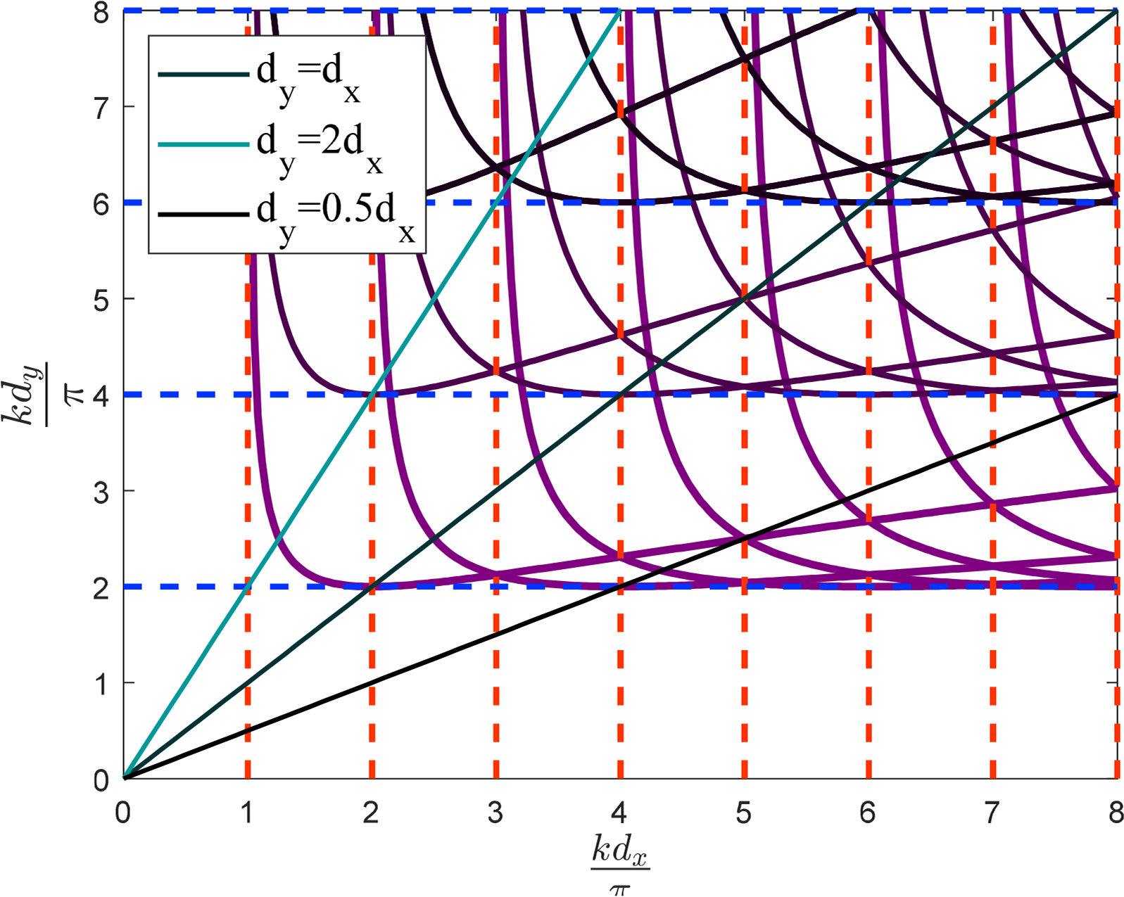
Resonance of a multi-row terminator array of vertical cylinders (Red line: Bragg resonance, Blue line: Rayleigh resonance, and Magenta line: Laue resonance)
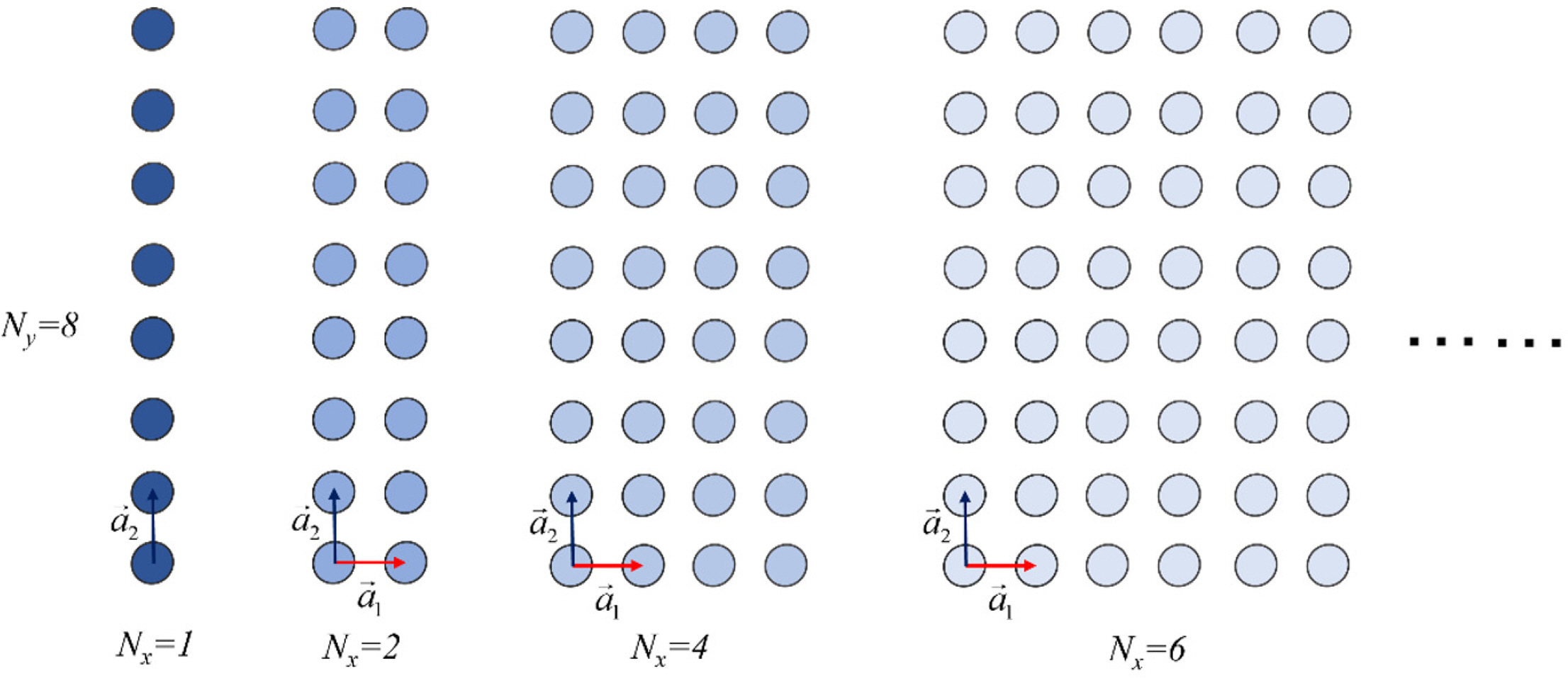
Various configurations of the multi-row terminator array of vertical cylinders considered in the analysis (Number of columns (Ny): 8)
Fig. 11 shows the non-dimensional average capture width of the multi-row terminator array of vertical cylinders for all the cases considered. In particular, the increment of the number of rows in these arrays reduces their energy absorption for a small kdy, as shown in the left side graphs of this figure. This reduction is obvious when the maximum kdy is smaller than the first Rayleigh resonance frequency.
The maximum energy absorption of general periodic WECs is limited by the normal component of the incident energy corresponding to the WECs’ maximum average capture width,(Wa)max = d, in the absence of oblique waves. Subsequently, we compute the maximum array gain qmax for an array of N rows in the absence of oblique waves (Tokić and Yue, 2019) using the array gain given by Eq. (11) and the maximum capture width of a heaving isolated buoy(kW)max = 1:
Fig. 2 of Tokić and Yue (2019) shows that the array gain cannot always attain the maximum value. Therefore, the number of rows is crucial in the case of a small kdy to achieve array gain. Hence, the increment of the number of rows in the multi-row terminator arrays of vertical cylinders results in a decrease of the average capture width of these arrays for small kdy values.
This analysis also confirms the resonance effect in the multi-row terminator array of vertical cylinders for various combinations of Nx and Ny. The red, blue, and magenta dotted lines in Fig. 11 denote the Bragg, Rayleigh, and Laue resonances, respectively, at each frequency. In addition, the gray line of this figure denotes the simultaneous existence of two resonance phenomena, and the black vertical line in this figure denotes the occurrence of all resonances simultaneously at this frequency. First, the effect of Bragg resonance seems small in all these array configurations. Next, the magnitude of the non-dimensional average capture width oscillates between resonance points generally. In addition, a lot of resonance points occur when dx and dy are sufficiently large. Particularly, several Laue resonance points are generated under this condition. Therefore, these arrays’ non-dimensional average capture width becomes extremely oscillating if the distance between adjacent buoys of these arrays is relatively large, as shown in the upper right graph of Fig. 11. However, a large amplitude occurs only when the number of rows in these arrays is smaller than five. Further, the extraction efficiency of the multi-row terminator array of vertical cylinders decreases when the number of rows in it is larger than four generally. Consequently, a smaller value for the number of rows in these arrays gives better performance than a corresponding single-row terminator array, provided the former has a moderate kdy.
3.4.2 A 4×8 multi-row array
Tokić (2016) attempted to find the local maximum of extracted power of a multi-row terminator array by using an optimization scheme for this array’s x- and y-directional distances between its rows and columns, respectively (dx and dy), that can vary inside the array. He found that the local maximum of this extracted power could be obtained for various dx and constant dy values within the array under regular water waves. Moreover, a regular array achieves a local maximum of extracted power at least when the inclined angle of irregular water waves is small (Tokić and Yue, 2021). Tokić and Yue (2021) also concluded that a perturbed position of each buoy results in less extracted power of this array.
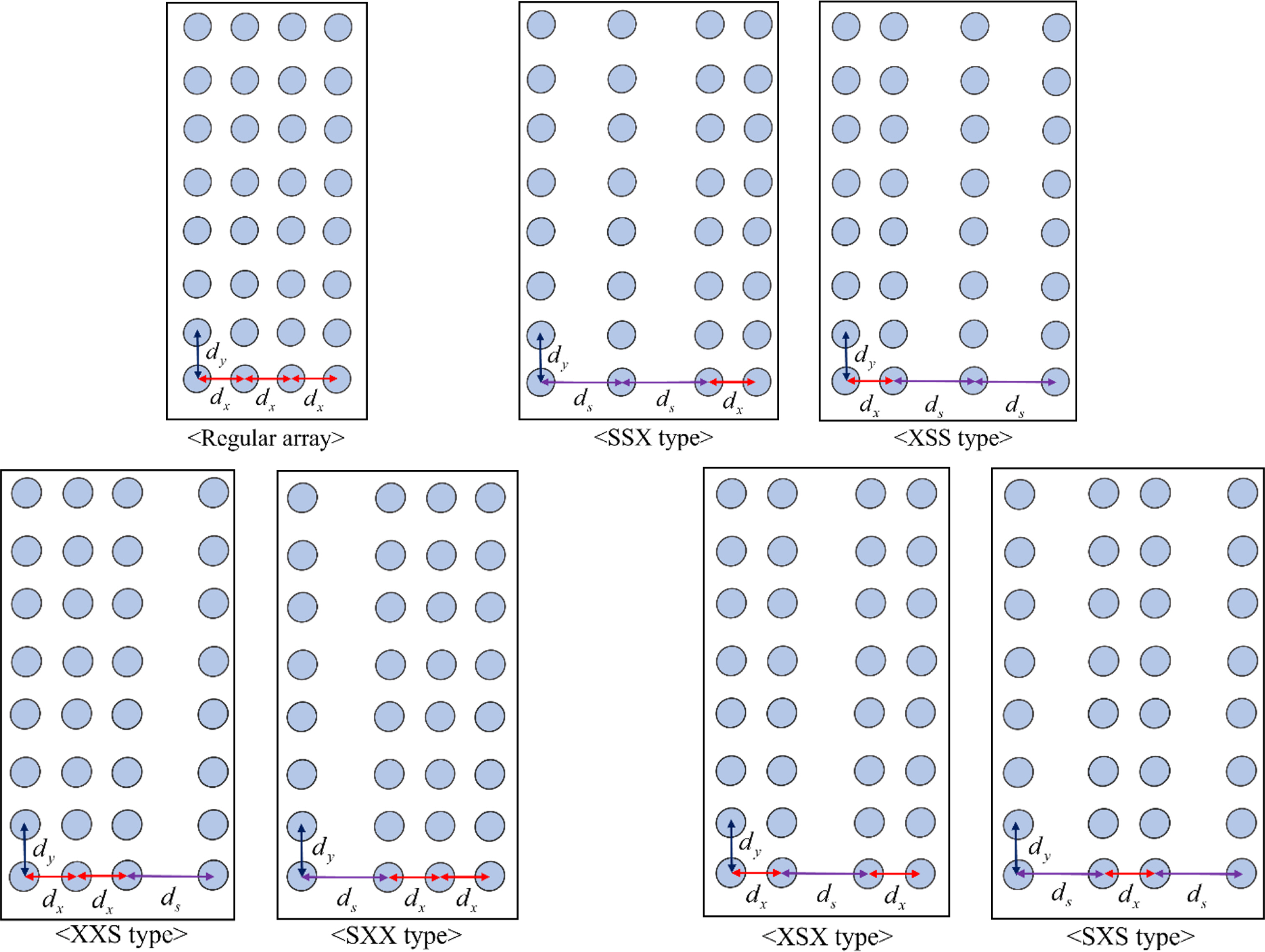
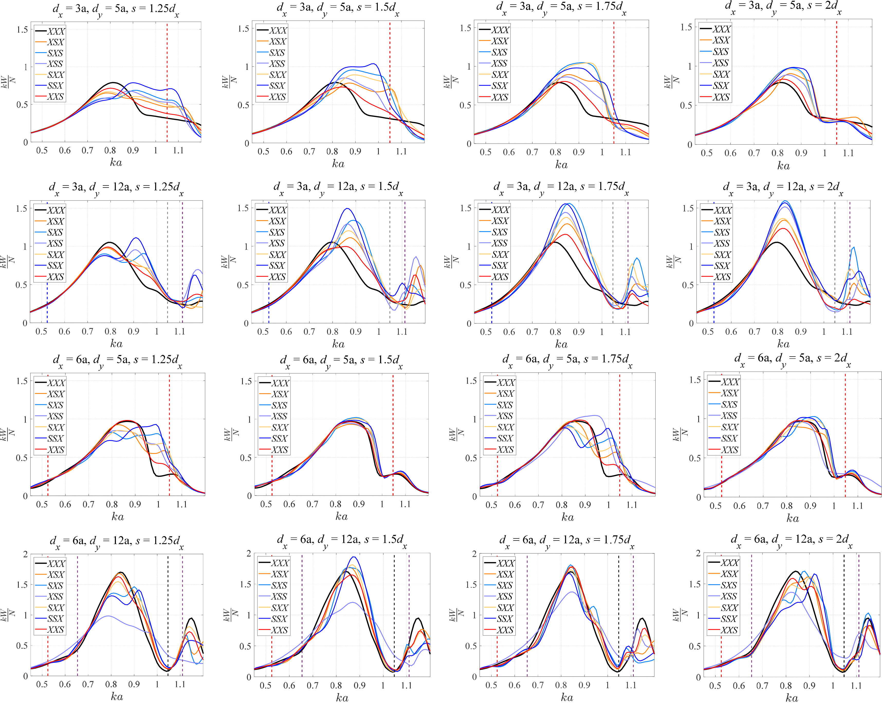
Our analysis of the single-row terminator array of vertical cylinders shows that a constant dy is constructive. In addition, achieving a local maximum of extracted power in a regular array under irregular water waves is possible only with an unconstrained total length of the array. On the other hand, a constrained overall length of an array together with various dx values within it results in better energy extraction efficiency of the array under some conditions. So, we investigate the extracted power of a 4×8 multi-row array of vertical cylinders with various dx values within it though under regular water waves. In addition, the distance between rows of this array is changed. In particular, we choose one regular 4×8 multi-row array of vertical cylinders and six variants of it with at least two same x-directional distances between the rows, as shown in Fig. 12. In addition, four combinations of distances are chosen for the analysis (dx = 3a, dy = 5a; dx = 3a, dy = 12a; dx = 6a, dy = 5a; and dx = 6a, dy = 12a). The ds in these arrangements is always greater than dx.
The results of the analysis on the 4×8 multi-row arrays of vertical cylinders are summarized in Fig. 13. The black line in this figure shows the non-dimensional average capture width of a regular 4×8 multi-row array of vertical cylinders. Other colorful lines denote the results for the corresponding arrays with various dx in them. In particular, dx influences the relative magnitude of the non-dimensional average capture width between this regular array and the other corresponding arrays with various dx. In addition, a small dx is constructive only in these arrays with various dx. Notably, various small dx (2.8a < dx < 3.5a) values result in larger energy extraction efficiency of any of these arrays with various dx than that of a corresponding regular array with the same dx. However, the details of the analyses giving this finding are not reported here. The graphs corresponding to dx = 3a in Fig. 13 have the colorful lines representing the non-dimensional average capture widths of these arrays with various dx which are larger than that (represented by the black line in this figure) of the corresponding regular array. On the other hand, the black line in the graphs corresponding to dx = 6a represents the non-dimensional average capture width of a regular 4×8 multi-row array of vertical cylinders, which is greater than those (represented by the colorful lines in this figure) of the corresponding arrays with various dx values. The energy extraction efficiency of all these multi-row terminal arrays of vertical cylinders with various dx is better than that of the corresponding regular array almost in all frequency ranges. So, we expect their similar high performances under irregular water waves. Unfortunately, it is difficult to find which of the 4×8 multi-row arrays of vertical cylinders with various dx is better. However, SSX and XXS types of these arrays have relatively large and small efficiencies, respectively, in many cases.
5. Conclusions
The energy extraction efficiency of multi-body wave energy converters (WECs) is investigated in this study using the generalized mode approach. In particular, the effect of the WECs’ configuration on their energy extraction efficiency is parametrically studied. First, the energy extraction efficiency of the single-row terminator and single-column attenuator arrays of vertical cylinders has been computed. The wall effect induced from periodic buoys positively affected the middle buoys of this terminator array. On the other hand, the corresponding attenuator array achieves a small energy extraction due to the wall effect except at the first few buoys. Subsequently, a terminator array with a few rows of vertical cylinders has been studied, and three resonances, i.e., Bragg, Rayleigh, and Laue resonances, are checked. The increment of rows in this terminator array results in its low energy extraction efficiency when the array has a small y-directional distance between its adjacent columns. On the other hand, the energy extraction efficiency of a multi-row array of vertical cylinders oscillates between the resonance frequencies greatly when a large y-directional distance between its adjacent columns is considered, and the number of rows is below five. Finally, a 4×8 terminator array of vertical cylinders having various dx or x-directional distance between its adjacent rows is studied. This study shows that a small dx results in better energy extraction efficiency of some of these arrays with various dx than that of a corresponding regular array with the same dx.
Notes
No potential conflict of interest relevant to this article was reported.
This research was supported by the Basic Science Research Program through the National Research Foundation of Korea (NRF) funded by the Ministry of Education (2020R1I1A1A01065411)

