1. Introduction
Currently, owing to global warming, climate disasters such as heatwaves, heavy rain, droughts, and typhoons are being frequently observed. According to the 6th evaluation report by the IPCC (Intergovernmental Panel on Climate Change), around ¾ of carbon dioxide emissions in the atmosphere over the past 20 years are due to fossil fuel combustion, and most of the global warming over the past 50 years is caused by an increase in greenhouse gas concentrations (Arias et al., 2021). Wind and solar power technology are actively being developed to generate power using renewable energy, which is one of the various methods of contributing to carbon neutrality, and technology for utilizing renewable ocean energy is actively being developed throughout the world. An oscillating water column wave energy converter (OWC-WEC) is a device that converts wave energy into electricity, and it comprises an oscillating-water-column chamber (OWC chamber), an air turbine, a generator, and a power conversion device. The heave motion of the water level inside the chamber caused by the incidence of waves generates an oscillating airflow. Mechanical equipment of OWC-WECs is simple and is not exposed to seawater owing to its primary energy conversion method. Therefore, OWC-WECs are the most promising ocean renewable energy technology in terms of durability and maintenance.
In power generation that utilizes renewable energy, the primary energy conversion efficiency has the most dominant effect on power generation performance. Recently, international joint research is underway to advance the technology of OWC-WECs under the technology collaboration program on Ocean Energy System (OES) established by the International Energy Agency (IEA) (Bingham et al., 2021). Pressure drops occur inside an OWC chamber as a turbine is driven by the airflow created in the OWC chamber. Wells turbines and impulse turbines typically used in OWC-WEC systems generates pressure drops that are linear and nonlinear in regard to the input flow velocity, respectively (Falco and Henriques, 2016). Kim et al. (2020) introduced linear potential-based numerical wave tanks (NWT) for hydrodynamic energy conversion simulations of OWC-WECs and solved the problem of turbine–chamber interaction by considering the properties of nonlinear pressure drops. Koo and Kim (2010) and Ning et al. (2015) introduced a nonlinear NWT technique to more closely consider the hydrodynamic properties that affect OWC energy conversion problems. Kim et al. (2021) simplified and solved the hydrodynamic energy conversion problems in irregular waves by applying a response spectrum method based on linear potential theory to OWC-WECs that use Wells turbines, which have linear pressure drop properties.
A commercial power plant that uses several OWC-WECs connected to a breakwater is being operated at Muturiku Harbor in Spain (Torre-Enciso et al., 2009; Garrido et al., 2015). These WECs are attached to onshore and offshore structures, and there is a need to develop technology regarding wave–structure interactions to efficiently use the limited space. Recently, several studies have examined the energy-conversion properties of OWC-WEC that use multiple chambers in limited spaces. Rezanejad et al. (2015) observed that energy conversion efficiency increased within an extended wave frequency range when multiple chambers were used along the direction of wave propagation, based on analytical and numerical methods. Subsequently, linear potential theory-based numerical studies were performed on the hydrodynamic performance of multiple chambers (Zheng et al., 2020; Wang et al., 2021), and studies based on CFD have been conducted to examine the complex, nonlinear hydrodynamic properties around multiple chambers (Elhanafi et al., 2018). Shalby et al. (2019) conducted model tests and CFD analysis on a WEC that combines four OWC chambers, and an orifice in each chamber was used to examine the pressure drop effects caused by the power take-off (PTO) system. Zhao et al. (2021) conducted the model test for single, dual, and triple OWC chambers to compare the hydrodynamic energy-conversion properties, and they measured the reflected waves and transmitted waves and comprehensively discussed the energy dissipation effect caused by multiple OWC chambers.
This study aims to discuss the hydrodynamic properties of multiple OWC chambers from the perspective of primary energy-conversion performance via a finite element method-based time-domain potential flow analysis. We herein examined the validity of numerical methods through a comparison with the results of model tests on multiple OWC chambers using a 2D wave tank by Zhao et al. (2021). It examined the behavior and energy conversion properties of OWCs over time in single, dual, and triple OWC chambers. In addition, this study used the time averages and standard deviation values of pneumatic power converted in the chambers to comprehensively review the effects of multiple OWC chambers on energy-conversion performance in terms of quantity and variability.
2. Numerical Analysis Method
2.1 Boundary Value Problem
A potential flow model was used to analyze the wave field around the OWC chamber. In the potential model, the boundary value problem regarding the linear velocity potential ϕ(1) is defined as shown below, assuming an incompressible, non-viscous ideal fluid.
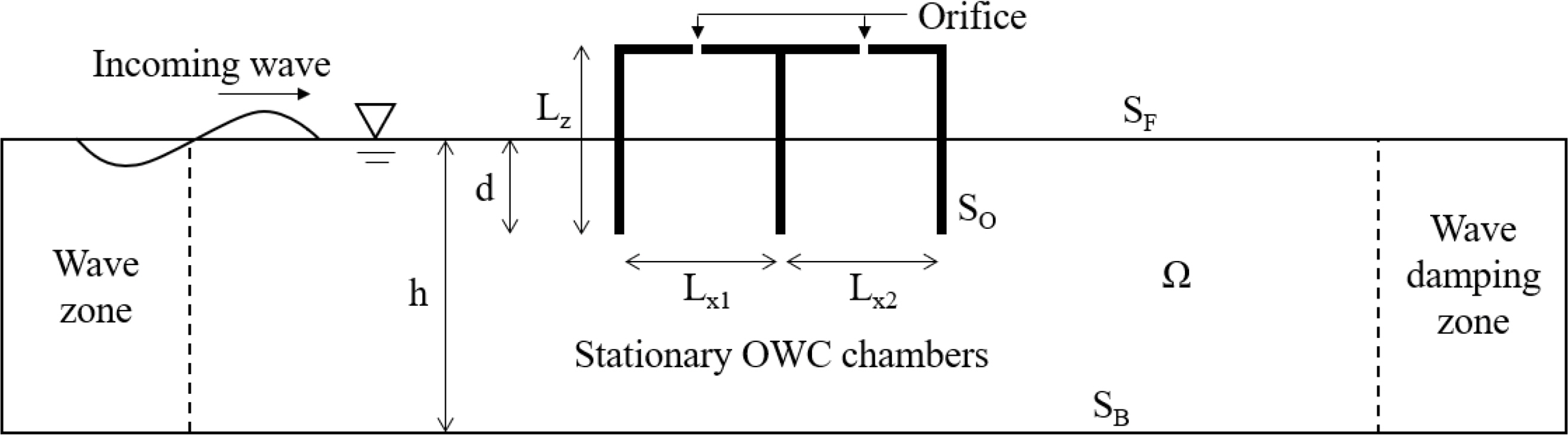
The Laplace equation in Eq. (1) is the governing equation for the potential flow of the overall fluid domain (Ω). Eqs. (2) and (3) denote the linearized hydrodynamic and kinematic boundary conditions on the free surface (SF ), respectively. The impermeable boundary condition in Eq. (4) was used in the bottom boundary (SB), object surface boundary (SO), and wall boundary (SW). Here, g is the gravitational acceleration, and ζ(1) is the linear wave elevation. n is the normal vector. Fig. 1 is a diagram of the vertical cross-section of a 3D NWT that includes multiple OWC chambers. To solve the hydrodynamic problem of an OWC chamber that is similar to the model tests in a 2D wave tank, each of the boundary conditions in Eqs. (1)–(4) were used, and a wave zone for generating incident waves and a wave damping zone for removing reflected waves were used before and after the fluid domain.
To take into account variability in the pressure generated by the air turbine, orifices were added, and the pressure drop (pd) inside the OWC chamber was set to be proportional to the square of the airflow velocity (Uo) through the orifices (Koo and Kim, 2010; Kim et al., 2020). In Eq. (6), a term for the pressure variability caused by the orifices was included in the dynamic free water surface boundary condition corresponding to the area inside the OWC chamber.
Here, γ is the pressure drop coefficient, and ρa is the air density. The airflow that occurs in the OWC chambers was calculated via the numerical integration of the free surface variability inside the OWC chambers, and the velocity (Uo) of the airflow that passed through the orifices was converted to satisfy the equation of continuity.
2.2 Finite Element Method
In this study, the finite element method was used to discretize the analysis fluid domain to solve the boundary value problem of multiple OWC chambers. The test function Ψ was introduced to construct a weak formulation of the governing equation as shown below.
Eqs. (8) and (9) show the 3D fluid domain’s velocity potential and free surface wave elevation, respectively, when the fluid domain is divided into a finite number of elements and the velocity potential function is approximated as a linear superposition of continuous and differentiable basis functions.
Here, Ni is the 3D basis function in the overall fluid domain, and Mk is the 2D basis function on the free surface. In this study, an 8-node hexahedral element was used in the 3D basis function, and a 4-node quadrilateral element was used in the 2D basis function. The Galerkin method was introduced to arrange the boundary value problem as a linear algebraic equation as shown below. The overall flow field and the free water surface’s velocity potential and wave elevation can be obtained through time integration using Eqs. (10)–(12).
The fourth-order Adams–Bashforth–Moulton method was used to perform free surface time integration in the numerical simulation. At each time interval, the velocity potential and wave elevation were predicted by Eq. (16), and Eq. (17) was used to perform iterative calculations until the potential and the wave elevation converged.
To eliminate the wave reflection from the external fluid domain, the wave damping zone technique was introduced to the free surface area near the outer region of the NWT, as shown in the equation below. The dynamic and kinematic free surface boundary conditions of the wave damping zone are shown in Eq. (18), and the wave frequency was used for the applied damping factor μ (Nam et al., 2009).
3. Numerical Analysis Results and Examination
3.1 Multiple OWC Chamber Modeling and Verification
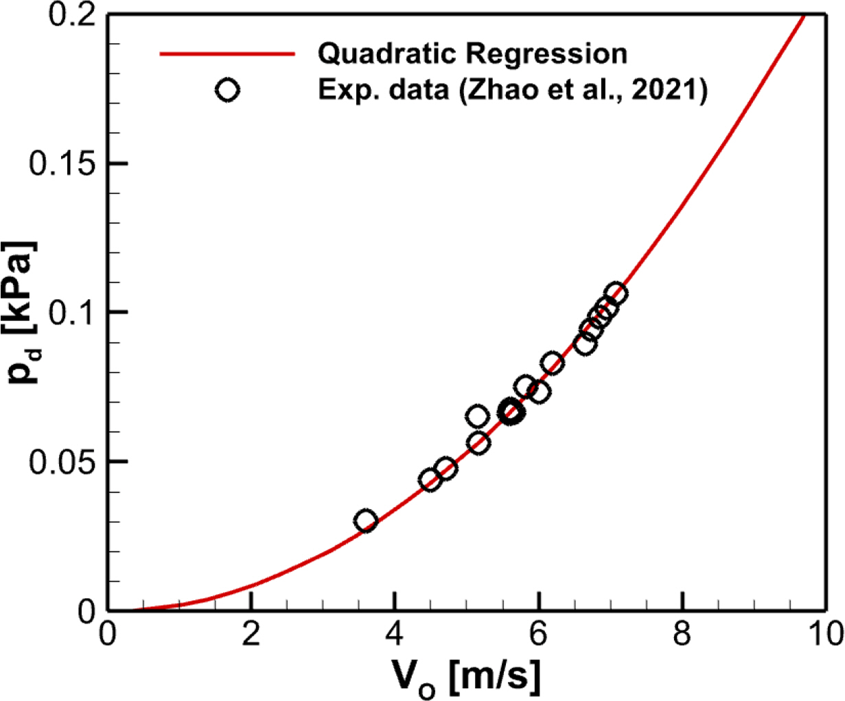
An orifice model is introduced to consider pressure fluctuation effects inside the OWC chambers caused by the air turbine operation. As shown in Fig. 2, the relationship between pressure drops and the airflow velocity that passes through the orifices was derived as a quadratic regression function by applying the least squares method based on the model test results of dual OWC chamber in Zhao et al. (2021). Here, the airflow velocity that passes through the orifices was estimated by using the amplitude of the OWC heave motion observed in the previous study, based on the premise that the OWC moves like a piston. The nonlinear pressure drop coefficient (γ) was 2.123 Pa/(m/s)2.
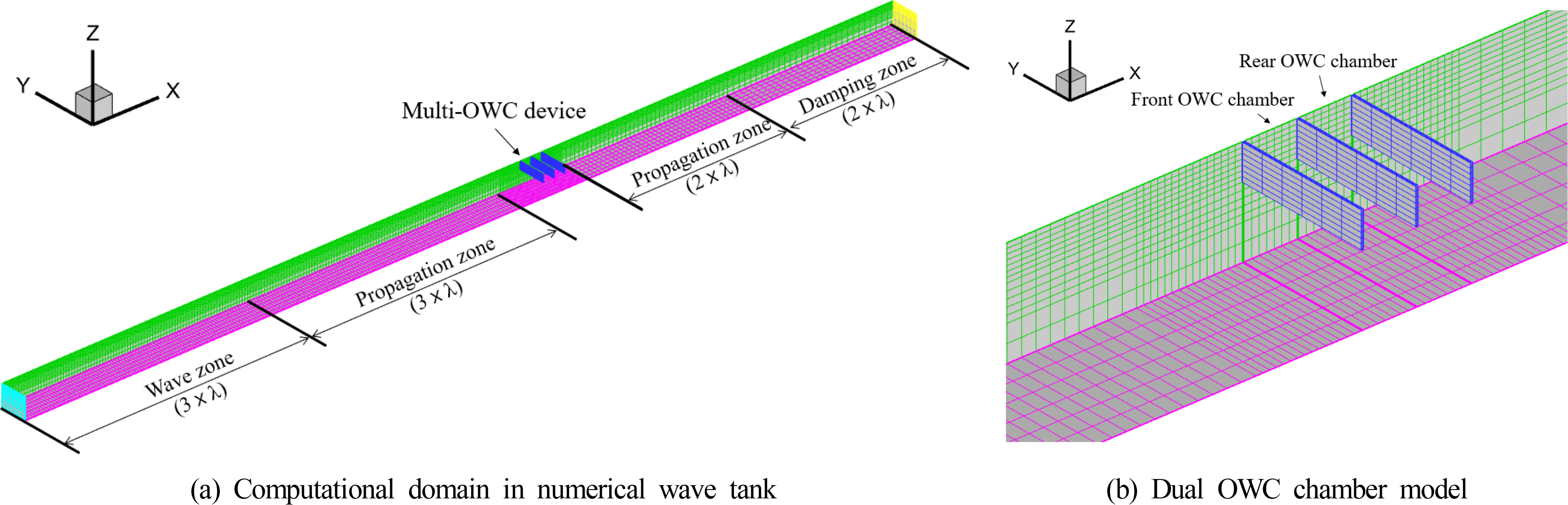
Table 1 shows the specific dimensions and wave conditions of the multiple OWC chamber model from the experiments of Zhao et al. (2021) for the verification of the present numerical method. The pressure drop relation derived from the model test data was applied to the dynamic free surface boundary conditions of the inside of each chamber in the multiple OWC-WEC based on Eq. (6). It was numerically implemented so that the pressure drop caused by the velocity of the airflow passing through the orifice acted on the free surfaces inside the OWC chambers. A time-domain numerical simulation for a dual OWC-WEC was conducted by using the finite element-based NWT, as shown in Fig. 3.
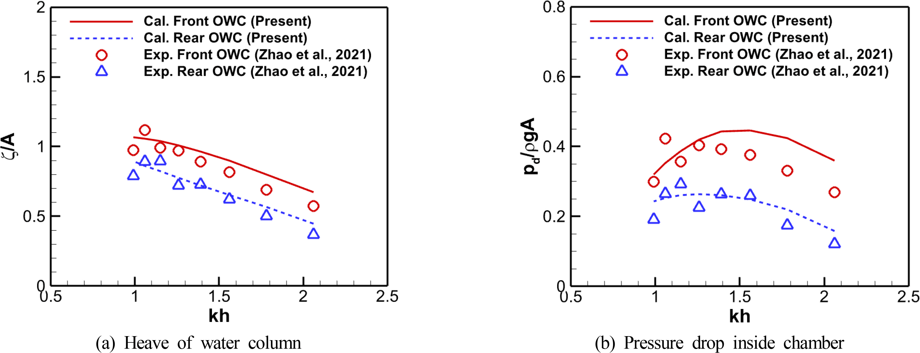
Fig. 4 compares the numerical results with the model test data regarding the free surface motion and the pressure drops inside dual OWC chambers. The free surface motion and pressure drop inside the OWC chambers showed a significant difference between the front and rear OWC chambers for entire wave conditions. The response in the rear OWC chamber was relatively small, and this pattern of the OWC chamber was observed in both the model tests and the numerical analysis. The overall numerical results agree well with the model test data, but in shortwave conditions with a dimensionless wave number (kh) of 1.3 or more, the free surface motion and pressure drop responses in the front OWC chamber tended to be overestimated. This is because there was limited consideration of the hydrodynamic energy loss caused by viscosity and vortices around the chamber structures, wherein it is the fundamental feature of a linear potential theory. In addition, according to Kim et al. (2020), when the relation between the OWC chamber’s length and the incident wavelength is lx/λ > 0.1, the water surface inside the OWC chamber shows an asymmetrical sloshing component. As lx/λ increases, the sloshing mode tends to grow gradually. In the case of the dual OWC chambers, part of the airflow generated in the OWC chambers was canceled out by a sloshing component in the water surface motion inside the OWC chambers at shorter wavelengths than kh = 1.26 (lx/λ ≃ 0.1). Therefore, the net airflow passing through the orifices in the model tests was different from the airflow that was indirectly estimated from the water surface displacement at the center of the OWC chamber. The numerical analysis results show high uncertainty under the short wave conditions because the numerical model is based on the empirical relationship between the converted airflow velocity and the pressure drops. In particular, this effect was significant in the front OWC chamber, where the incident waves arrived first.
3.2 Hydrodynamic Behavior Properties in Multiple OWCs
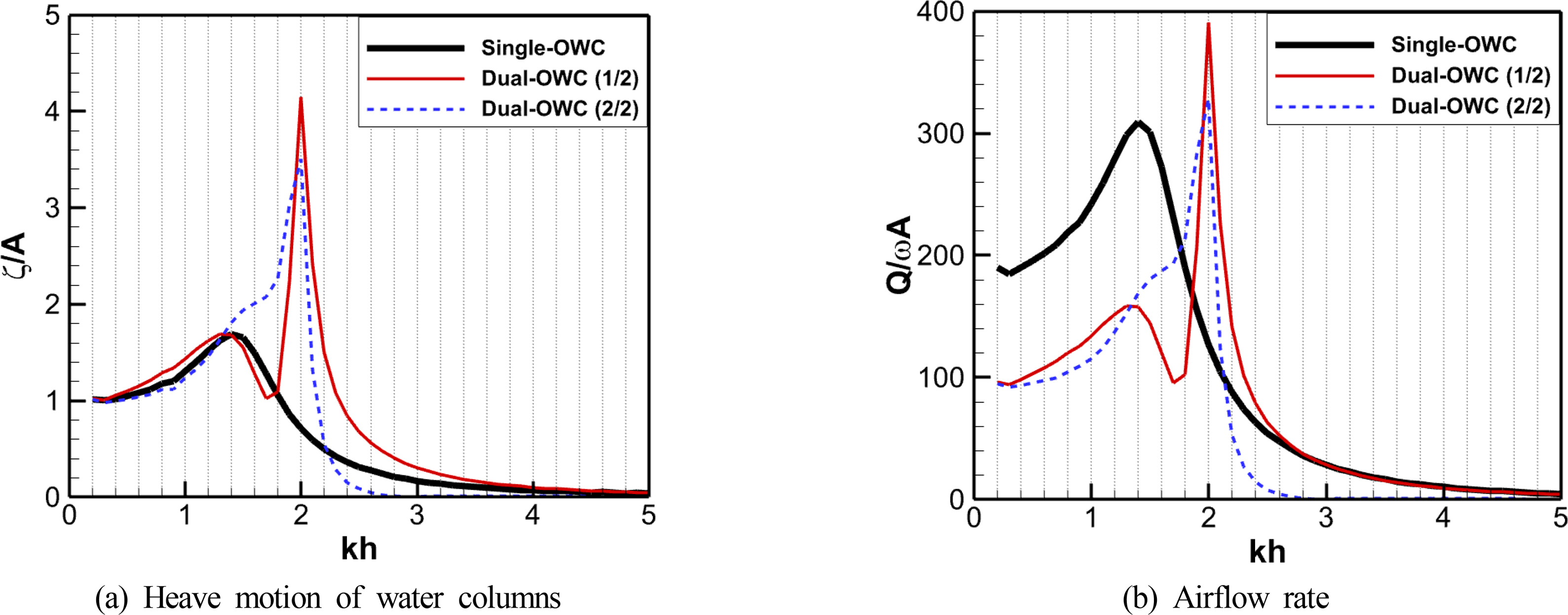
To analyze the effect of multiple OWC chambers on the hydrodynamic behavior of the oscillating water column, numerical simulations were performed by changing the number of OWC chambers for the WEC device of the same size in regular waves. First, in order to focus on the hydrodynamic performance of the OWC chambers, the pressure drop effect caused by the air turbines, which are the energy extraction system (PTO system) of OWC-WEC, was excluded from the numerical analysis. Fig. 5 shows the ratio of the OWC’s heave motion to the incident wave amplitude. Fig 5(a) shows the response for single and dual water column chambers, and Fig. 5(b) shows the response of the single and triple OWC chambers. Here, the OWC’s motion represents the wave elevation measured by wave probes installed in the centers of the water column chambers, and the incident amplitude (A ) was considered to be 1.0 m. In the numerical results for the single OWC chamber, the OWC had the greatest heave motion at an incident wave of kh = 1.4. On the contrary, in the case of the dual and triple OWC chambers, the OWC’s heave motion was greatest in shortwave conditions at values of 2.0–2.3, and the motion’s amplitude was sensitive to changes in the incident wavelength.
When the incident waves in the dual OWC chambers were shorter than in peak conditions, the oscillating water column motion increased in the front OWC chamber and decreased in the rear OWC chamber, as shown in Fig. 5(a). In longer wave conditions, the front chamber of the dual OWC device showed a similar heave motion trend as the single OWC device, but the heave motion of the rear chamber increased. Looking at the hydrodynamic behavior of the oscillating water column according to the division of the OWC chambers, the motion response tended to increase within a relatively narrow incident wave range.
Fig. 6 shows the OWC motion and surrounding wave fields when using single, dual, and triple OWC chambers. The incident wave conditions of these simulations were kh = 2.0, A = 1.0 m, and the wave fields were divided according to the phase of the free surface displacement measured at the front of the OWC chambers. Inside the single OWC chambers shown in Figs. 6(a) and 6(c), it was observed that the OWC’s heave motion included asymmetrical sloshing in the longitudinal direction of the OWC chamber. Here, the ratio of the sloshing amplitude to the heave motion amplitude of OWC, which was calculated based on the average water level inside the OWC chamber, was ζsloshing/ζOWC = 0.303. However, in the case of the multiple OWC chambers created by dividing the same OWC chamber, the sloshing component inside the chamber was converted into a rising or falling motion according to the location of the multiple OWC chambers. As a result, the free surfaces inside each OWC chamber tended to have a piston-type heave motion with a phase difference. In the numerical simulation for the single OWC chamber, it was observed that the radiated waves caused by the motion of the OWC, the reflected waves from the structure, and the incident waves achieved a quasi-steady equilibrium, and perfect standing waves developed in the front wave field. However, as shown in the figures in the center and right column of Fig. 6, there were multiple radiated wave components generated by each OWC heaving at different phases inside the multiple OWC chambers, and the front wave field showed a more irregular pattern than the analysis results from the single OWC chamber.
A hydrodynamic analysis is required to examine motion responses that include interaction with multiple OWCs. According to Kim (2021), the natural frequency for the heave motion of an OWC can be expressed by the mass, added mass, and restoring force coefficient of OWC, as shown in Eq. (19), and the added mass depends on the excitation frequency.
Here, ωn, ω, m, k, and a are the natural frequency of OWC, the wave angular frequency, mass, restoring force coefficient, and added mass, respectively.
Table 2 shows the specifications of single and multiple OWCs and the resonant wave conditions. In the case of a single OWC, the greatest heave motion was seen at an incident wave of kh = 1.4, where the ratio of the OWC chamber to the incident wavelength was lx/λ = 0.223. According to Kim et al. (2020), a heave motion of the OWC under the condition of lx/λ = 0.223 includes a sloshing component. In the numerical analysis results of multiple OWC chambers, the maximum response of each OWCs occurred at a shorter wavelength than that of the single OWC chamber, and the ratios (lx/λ) of the OWC chambers to the incident wavelengths corresponding to these wave conditions were 0.106–0.159. The multiple OWC chambers exhibited the maximum response when the incident wave had a longer wavelength than the length of the OWC chamber, which implies that the piston-type heave motion is more dominant in comparison to the single OWC chamber. The added mass was estimated from the wave conditions wherein the single and multiple OWCs showed the maximum response based on Eq. (19). The added mass of the single OWC chamber, wherein the sloshing motion was significant, was around 1.42 times that of the OWC mass. The added mass ratio of the dual OWCs, wherein the piston motion was dominant, was a/m = 0.556, and the added mass ratio of the triple OWCs was 0.398–0.556, showing that the added mass ratio decreased by around 60%–77% compared to the single OWC chamber. In the case of the multiple OWC chambers, the maximum response occurred at a shorter wavelength than in the case of the single OWC chamber. Thus, multiple OWCs can be seen as beneficial for wave energy absorption under the short period conditions because the net airflow cancellation effect caused by sloshing mode can be reduced as the piston motion becomes dominant.
3.3 Energy Extraction Properties of Multiple OWC Systems According to the Use of PTO
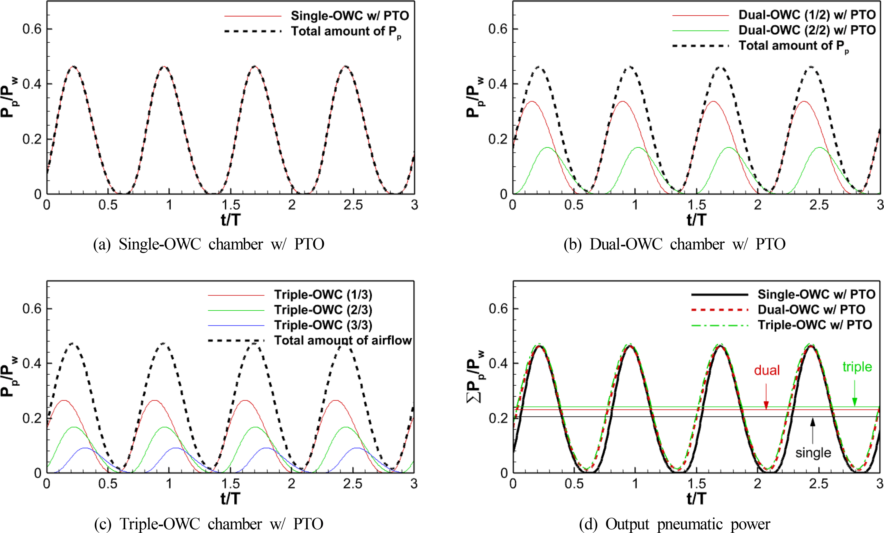
The heave motion of the oscillating water column generates an airflow that passes the turbine connected to the OWC chamber. From the perspective of a WEC device, it is necessary to discuss the performance in terms of total energy converted by multiple OWC chambers. Fig. 7 shows the time-series of the airflow rate generated by each OWC chamber of the single, dual, and triple OWC-WECs. The single OWC chamber exhibited a time-series response that momentarily included a zero flow rate during each wave cycle when the intake and exhaust airflows were switched by the vertical motion of the waves. However, in the case of the multiple OWC chambers, the flow rate that was generated by the WEC device over time always had a positive value due to the phase difference between each OWC motion.
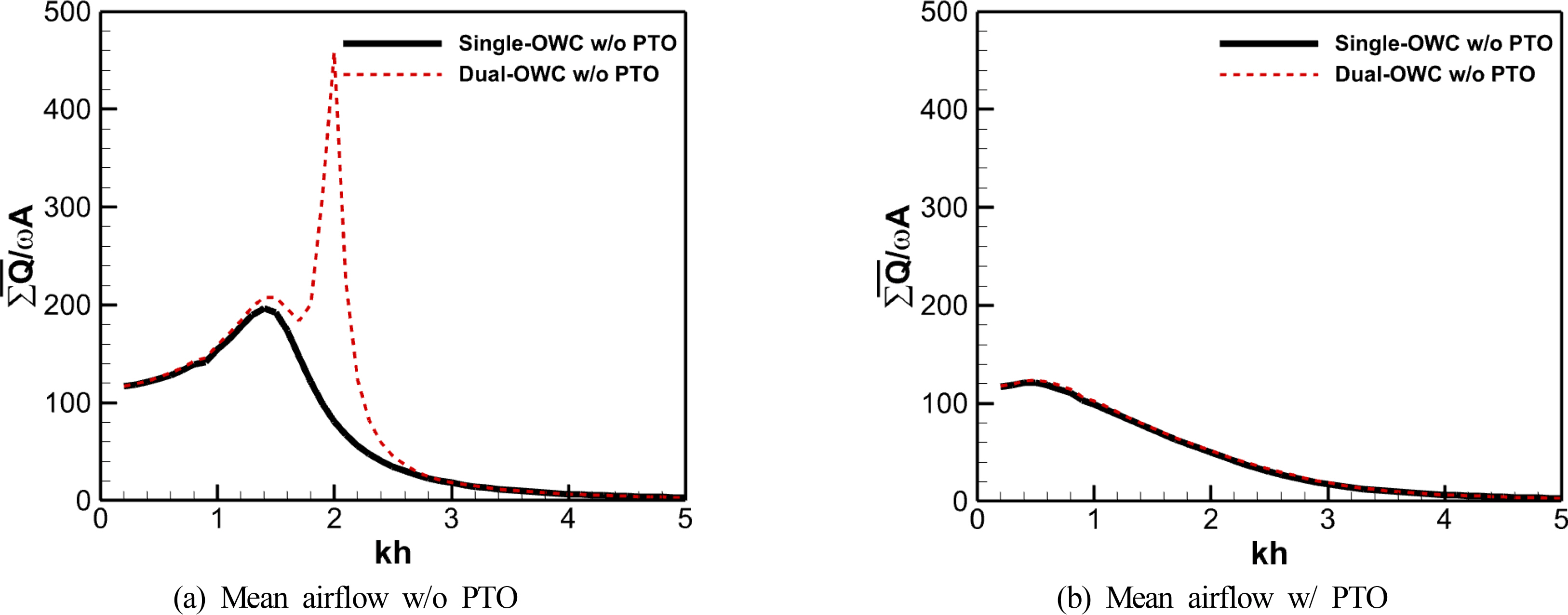
Fig. 8 shows the amplitude of the total airflow rates generated by the single and dual OWC chambers. Regarding the numerical results without the PTO system in Fig. 8(a), excessive airflow occurred due to the resonant motion of the multiple OWCs in wave conditions where kh was 2.0–2.3. However, the numerical results with the PTO system in Fig. 8(b) show that the airflow in the multiple OWC chambers was similar to that of the single OWC chamber. This can be seen as the excessive OWC motion being damped by the pressure inside the OWC chambers due to the orifice effect. This means that the flow rate created by the device was similar, but there was a difference in the pressure drops acting on each OWC chamber. According to Fig. 9(a), in the case of the dual OWC chambers, a relatively higher pressure drop occurred in the front chamber, which encounters the incident wave first, and this value was higher than the pressure drop that occurred in the single OWC chamber. This implies that optimizing the capacity of the PTO system is necessary for each chamber of multiple OWC-WEC along the direction of the wave propagation.
Variability in the electric power generated by renewable energy converters is not a problem when renewable energy sources account for a small share of the power grid; however, as the share gradually increases, this variability may affect the stability and quality of the power grid (Schmietendorf et al., 2017). Fig. 10 shows the time series of pneumatic power that was converted in the single and dual OWC chambers. As shown in Figs. 10(b) and 10(c), the pneumatic power of the multiple OWC chambers had a phase difference due to the successive action of the wave energy according to the location of each chamber. This phase difference reduced variability in the final output of the device. In Fig. 10(d), it can be seen that the time-series amplitudes of final pneumatic power in the OWC-WECs with single and multiple chambers were almost the same; however, the time-averaged pneumatic power of the multiple chambers was higher than that of the single chamber.
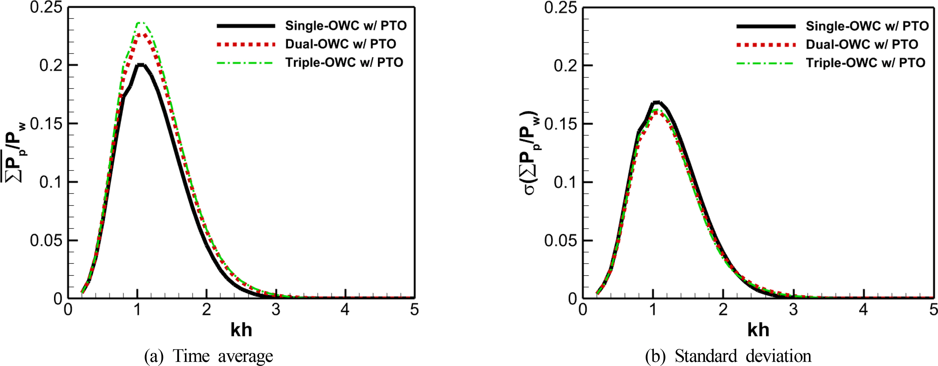
Fig. 11 shows the time-averages and standard deviation of the pneumatic power that was converted in the OWC-WECs with single and dual OWC chambers under various incident wave conditions. The maximum time-averaged pneumatic power of dual and triple OWC chambers were 13.3% and 18.2% higher than that of the single chamber at kh = 1.1, respectively. The devices that used multiple OWC chambers tended to show higher time-averaged pneumatic power at kh > 0.8 than a single OWC chamber, and this difference was clearly observed at 0.8 < kh < 1.8, where the pneumatic power generation was highest. The variability in pneumatic power in the dual and triple OWC chambers followed similar patterns, and the standard deviations of the pneumatic power over time in the dual and triple chambers were reduced by 5.1% and 3.6% under the wave condition showing maximum energy-conversion performance, respectively.
4. Conclusions
This study discussed the hydrodynamic characteristics and energy extraction performance of multiple OWC chambers based on numerical simulation using a 3D numerical wave tank. The developed numerical methods were used to perform various numerical simulations on multiple OWC chambers and examine the improvements in energy extraction performance in terms of the amount and variability of pneumatic power. To confirm the validity of the present numerical methods, the numerical results were compared with model test data from a previous study, and it was observed that they agree well under various wave conditions. The numerical simulations confirm that the motion of the water column that includes a sloshing component in the single OWC chamber can be converted to the piston motions with different phases in the multiple OWC chambers. The piston motion in the multiple OWC chambers mitigated the net flow reduction caused by the sloshing motion and generated considerable airflow at certain wave frequencies due to the resonance response. However, when the PTO system was considered, the excessive resonance response tended to decrease rapidly due to the damping force caused by the pressure drop. In addition, the division of the OWC chamber had the effect of reducing the temporal variability of the final output power of the generator due to the phase difference in the wave motion acting on each water column. Regarding the energy conversion performance at various wave frequencies, there was a tendency wherein the time-averaged pneumatic power increased, and the variability decreased owing to the utilization of multiple OWC chambers. It is confirmed that the utilization of multiple OWC chambers improves the energy conversion performance of OWC-WECs in terms of the amount and variability of the final pneumatic power. Based on the results of this study, future studies will focus on optimal usage methods for multiple OWCs and the effect of multiple OWCs in numerical simulations that consider realistic PTO systems.