Numerical Analyses on the Formation, Propagation, and Deformation of Landslide Tsunami Using LS-DYNA and NWT
Article information
Abstract
Generally, tsunamis are generated by the rapid crustal movements of the ocean floor. Other factors of tsunami generation include landslides on coastal and ocean floor slopes, glacier collapses, and meteorite collisions. In this study, two numerical analyses were conducted to examine the formation, propagation, and deformation properties of landslide tsunamis. First, LS-DYNA was adopted to simulate the formation and propagation processes of tsunamis generated by dropping rigid bodies. The generated tsunamis had smaller wave heights and wider waveforms during their propagation, and their waveforms and flow velocities resembled those of theoretical solitary waves after a certain distance. Second, after the formation of the landslide tsunami, a tsunami based on the solitary wave approximation theory was generated in a numerical wave tank (NWT) with a computational domain that considered the stability/steady phase. The comparison of two numerical analysis results over a certain distance indicated that the waveform and flow velocity were approximately equal, and the maximum wave pressures acting on the upright wall also exhibited similar distributions. Therefore, an effective numerical model such as LS-DYNA was necessary to analyze the formation and initial deformations of the landslide tsunami, while an NWT with the wave generation method based on the solitary wave approximation theory was sufficient above a certain distance.
1. Introduction
Generally, tsunamis are fluid movements that occur during the process of converting the potential and kinetic energies generated by rapid crustal movements such as earthquakes and volcanoes on the ocean floor. In addition, waves generated by coastal slope collapses, seamount landslides, glacier collapses, and meteorite impacts are also classified as tsunamis. Only a few examples of damage due to landslide tsunamis exist; however, single occurrences can trigger large numbers of casualties. In 1963, a tsunami occurred due to the impact of falling rocks and soil from a landslide that occurred in the Vajont Valley in northern Italy, and the resulting overflow caused approximately 2000 deaths downstream of the dam (von Hardenberg, 2011). In 2015, a landslide tsunami occurred at the Daning River area in Chongqing, Wushan County, China, causing 5 deaths and damaging 21 small ships (Xiao et al., 2018). In 2020, a tsunami occurred due to a landslide caused by rainfall at a jade mine in the Hpakant region of Myanmar, and a minimum of 172 deaths were reported (Lin et al., 2021).
Despite these incidents, no research has been conducted on landslide tsunamis in South Korea. Globally, there has also been a lack of studies on landslide tsunamis. Considering the major studies on this topic, Heinrich (1992) adopted 2D hydraulic-model experiments and NASA-volume of fluid (VOF) to compare and analyze the displacement of the water surface caused by objects sliding on a 45° inclined plane. Monaghan and Kos (2000) adopted 2D hydraulic model experiments and a smoothed particle hydrodynamics (SPH) model to examine the shapes of water surfaces during the generation of waves by vertically falling objects. Di Risio (2005) examined the mechanism of water surface wave generation and propagation according to the size of vertically falling rectangular objects in a 2D water tank. Massel and Przyborska (2013) performed a numerical analysis on wave generation and propagation according to four types of glacier collapses. Lindstrøm (2016) examined the water surface displacement of waves generated by five types of materials sliding on an inclined plane. Yeylaghi et al. (2017) performed a study using incompressible SPH, which improves upon SPH in 2D and 3D, and then compared experiments on landslide tsunamis (Heinrich, 1992; Rzadkiewicz et al., 1997; Monaghan and Kos, 2000; Heller et al., 2016).
This study adopted LS-DYNA and a numerical wave tank (NWT) to numerically analyze the generation and propagation characteristics of landslide tsunamis. Before performing the LS-DYNA analysis, the effectiveness and validity of the numerical model were verified by reviewing it and comparing it to numerical model experiments (Di Risio, 2005). Subsequently, LS-DYNA’s arbitrary Lagrangian-Eulerian (ALE) technique was adopted to investigate the waveform and flow velocity that occurred during the processes of wave generation and propagation due to falling objects, as well as compare it with theoretical solitary wave. In addition, it was necessary to simulate solitary waves in an NWT to analyze their hydraulic characteristics and compare them with landslide tsunamis in LS-DYNA. Furthermore, the FSI-based landslide tsunami analysis method in LS-DYNA and the approximation theory-based solitary wave analysis method in the NWT were adopted to examine their effectiveness.
2. LS-DYNA Analysis
LS-DYNA is a finite element method (FEM) program that is specialized for solving complex nonlinear problems such as collisions, collapses, material molding, etc., based on an explicit method; in addition, it can solve problems related to complex fluid motion caused by fluid-structure interaction (FSI).
2.1 LS-DYNA
The ALE method (Santini et al., 1998; Souli et al., 2000; Seddon et al., 2004; Poehlmann-Martins et al., 2005) directly solves FSI by coupling Lagrangian structures and Eulerian fluid domains, and also recalculates the modification of elements due to excessive deformation and the material properties of modified elements. The relationships between the ALE equation’s material time derivative and reference configuration time derivative are expressed as:
In LS-DYNA, the ALE method employs the conservation equation from FEM to trace the mass, energy, and momentum movements between elements. The ALE method’s equations for mass, momentum, and energy conservation are expressed as:
2.2 Validation of LS-DYNA
To verify the validity and effectiveness of the LS-DYNA program adopted in this study, a computational domain based on Di Risio’s (2015) experiments was created, as illustrated in Fig. 1. The length, height, and depth of the computational domain are 5 m, 0.2 m, and 0.1 m, respectively, and opacity was applied to both sides, the floor and ceiling. The falling object is a rectangular polyvinyl chloride box with vertical and horizontal dimensions of 0.1 m and 0.1 m, respectively. Regarding the experiment conditions, 0.3 m of the box was underwater, while 0.07 m was exposed outside the still water surface, and then it was dropped. The fluid domain’s computational grid comprised 0.01 m and 0.005 m horizontal and vertical equidistant intervals, respectively. The rectangular box comprised a computational grid with 0.02 m and 0.01 m horizontal and vertical equidistant intervals, respectively. The material properties of the rectangular box were the values provided by the Ansys company, and the unit weight, Young’s modulus, and Poisson ratio were set at 1330 kg/m3, 32.4 MPa, and 0.475, respectively. In addition, the fluid (water) density was 1000 kg/m3.

Computational domain based on Di Risio (2005)’s experiments
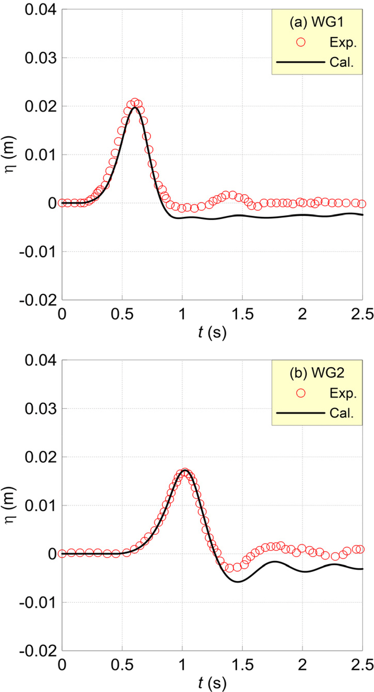
When the box was dropped, as illustrated in Fig. 2, the water surface waveform presented in Fig. 3 occurred. The red circles in Fig. 2 and 3 represent Di Risio’s (2005) experimental results, while the black solid lines depict the computational results from LS-DYNA.
Based on Fig. 3, the computational values of LS-DYNA could not completely recreate the water level drawdown of a seismic tsunami that occurs due to vertically falling objects; however, the overall waveform distribution was similar. The maximum water level of the landslide tsunami was recreated with a high level of accuracy, and the propagation rate matched well. Accordingly, it is possible to verify the validity and effectiveness of LS-DYNA in terms of modeling the generation and propagation of landslide tsunamis.
2.3 Computation Conditions
In this study, a numerical water basin was created, as illustrated in Fig. 4, to elucidate the generation and propagation processes of landslide tsunami waves in a numerical analysis using LS-DYNA. The tank was set up to be 10 m longer than Di Risio’s (2005) experimental water tank, and an impermeable vertical wall was installed at the end of the tank. The computational grid consisted of 0.01 m horizontal and vertical equidistant intervals, respectively. The other computational conditions were the same as those in Fig. 1.
At WG1, WG2, and WG3 in the numerical water basin presented in Fig. 4, the landslide tsunami and the solitary wave approximation theory’s waveforms and flow velocities were compared, and at WG4, WG5, and WG6, the waveforms and flow velocities that were each calculated in LS-DYNA and the NWT were compared. In addition, this study compared and reviewed the waveforms and wave pressure acting on the vertical wall in LS-DYNA and NWT at WG5, which was directly in front of the vertical wall.
2.4 Analysis Results
2.4.1 Formation of landslide tsunami
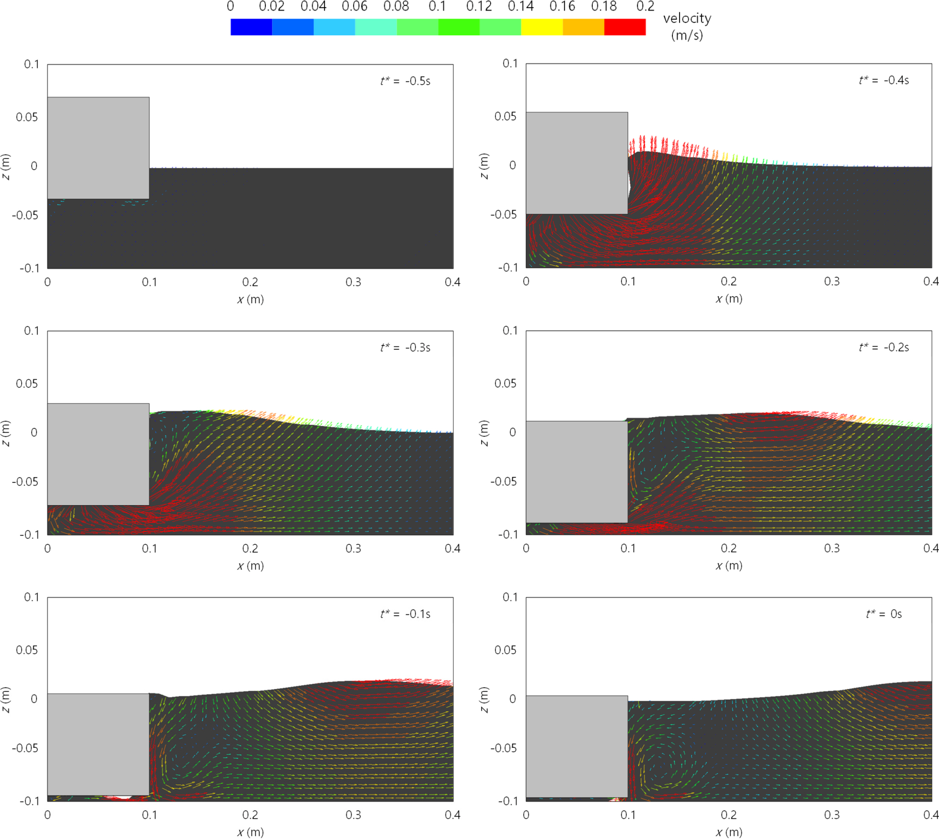
Fig. 5 presents the flow and wave fields during the process of wave generation due to a falling object. In Fig. 5, t* is based on the time point at which the maximum water level occurs at x = 0.4 m.
Water surface deformation occurs as the falling object’s potential energy is transferred to the fluid, and the tsunamis generated in this manner propagate along the tank. Notably, the inflow of air that occurred at (b) t* = −0.4 s is a feature of the landslide tsunami generation process that was also observed in the experiments conducted by Monaghan and Kos (2000). The wave and flow fields of the landslide tsunami exhibited characteristics similar to a solitary wave at (e) t* = −0.1 s.
2.4.2 Propagation of landslide tsunami
To understand the characteristics of wave deformation during a landslide tsunami’s propagation process, a comparison was made with Dean and Dalrymple’s (1984) approximate solitary wave. The solitary wave approximation formula for water-surface displacement and vertical and horizontal flow velocities are expressed as:
Fig. 6 compares the waveform computed in LS-DYNA and the solitary wave approximation theory waveform obtained during the landslide tsunami propagation process. The solitary wave theoretical waveform was calculated based on Eq. (5) using the maximum water level obtained in LS-DYNA. In Fig. 6, (a), (b), and (c) represent WG1, WG2, and WG3 at the 0.4 m, 5 m, and 9.3 m points, respectively. In addition, the red circles in each graph depict the theoretical values, while the black solid lines represent the computed values.
In Fig. 6(a), it can be observed that the initial waveform of the landslide tsunami computed in LS-DYNA was narrower than the theoretical solitary wave with a stable waveform in which nonlinearity and dispersion are balanced. Although the landslide tsunami caused by the falling object exhibited an asymmetric water surface owing to inflow and rising of bubbles, as it propagated, the wave height reduced and the waveform increased, gradually mitigating the asymmetry. Furthermore, in Fig. 6(c), the waveform is similar to the theoretical solitary wave, although it did not have a completely symmetrical water surface waveform owing to the effect of the inflowing bubbles when the object fell.
2.4.3 Flow velocity of landslide tsunami
Figs. 7 and 8 present the horizontal and vertical flow velocities of the landslide tsunami, together with the solitary wave’s theoretical flow velocities at WG1, WG2, and WG3, which exhibit the water surface waveform.

Comparisons of theoretical and numerical horizontal velocities at (a) x = 0.4 m, (b) x = 5 m and (c) x = 9.3 m

Comparisons of theoretical and numerical vertical velocities at (a) x = 0.4 m, (b) x = 5 m and (c) x = 9.3 m
At WG1 in the vicinity of the point where the landslide tsunami was generated, the horizontal flow velocity (u) computed in LS-DYNA was distributed more narrowly than the solitary wave’s theoretical horizontal flow velocity, while the vertical flow velocity (w) distribution of the computed flow velocity was considerably larger than that of the theoretical flow velocity. This is considered to be because of the difference between the stable theoretical solitary wave and the water surface waveform generated as the falling object’s potential energy is transferred, as illustrated in Fig. 6. Consequently, + u and + w are larger than the solitary wave approximation at WG1, while − u and − w increase because the water level drops below the still water level. As the horizontal and vertical flow velocities propagate throughout the water tank, the difference between the theoretical flow velocities decreases, and a similar distribution is observed, just as the water surface waveform is similar to the solitary wave. However, the horizontal flow velocity is discontinuous owing to the effect of bubbles flowing in when the object falls, and differs from the theoretical flow velocity distribution.
2.4.4 Deformation of landslide tsunami
To analyze wave deformation characteristics resulting from the propagation of a landslide tsunami, Fig. 9 illustrates the changes in wave height and volume ratios compared to the theoretical solitary wave. Here, V denotes the volume of the landslide tsunami waveform computed in LS-DYNA. V0 represents the volume of the theoretical solitary waveform. In addition, H denotes the computed wave height, while H0 represents the computed wave height at point WG1 (x = 0.4 m).
As observed in the time-domain waveform comparison with the theoretical solitary wave in Fig. 6, Fig. 9 demonstrates that the waveform is narrow, while the wave height is high during the initial generation of the landslide tsunami. The wave height of the generated landslide tsunami decreased, while the volume in comparison to the solitary wave increased; then, beyond a certain distance, the range of change decreased significantly. This is because, as the generated landslide tsunami propagated, it entered a stable/steady state in which nonlinearity and dispersion were balanced. Consequently, the landslide tsunami’s waveform became similar to the theoretical solitary wave at x = 9.3 m, and the horizontal and vertical flow velocities were also similar to the theoretical solitary wave, as illustrated in Fig. 6(c), 7(c), and 8(c). At x = 9.3 m, H/H0 was 0.58, while V/V0 was 0.91, and it was determined that the landslide tsunami had entered an almost stable/steady state.
3. NWT Analysis
To examine the hydraulic characteristics of landslide tsunamis that propagate beyond a certain distance, this study performed LS-DYNA analysis, including NWT analysis, which is based on the finite difference method. An NWT is a full non-linear 2-D Navier-Stokes solver (Lee et al., 2018) improved by proposing the tsunami generation method from Lee et al. (2016) based on Hur et al. (2011).
The effectiveness and validity of NWTs were confirmed in a comparison with hydraulic model tests (Hunt, 2003) on the propagation of solitary waves, wave shoaling on a slope beach, and wave overtopping on a seawall in Lee et al. (2018). Furthermore, in the study conducted by Lee et al. (2019), experimental results (Synolakis, 1987) on the phenomenon of solitary wave run-up on a beach were reproduced in an NWT with a high degree of agreement.
3.1 Governing Equation
The NWT’s governing equation comprises the following equation of continuity for making solitary waves in an incompressible and viscous fluid, as well as a Navier-Stokes equation of momentum.
To track a complex free water surface like a breaking wave, an advection function of the VOF is adopted (Hirt and Nichols, 1981). This can be expressed as a fluid conservation formula as defined below, based on the assumption of a non-compressible fluid.
3.2 Solitary Wave Generator
To generate solitary waves in the NWT in a stable manner, this study adopted a method proposed by Lee et al. (2016), which is based on a wave generation intensity equation using non-reflected wave system presented by Brorsen and Larsen (1987). In addition, it is difficult to accurately generate the target waveform when the incident wave and reflected waves overlap; therefore, the intensity adjustment factor ((η +h)/(ηs + h)) proposed by Ohyama and Nadaoka (1991) was adopted to make solitary waves in a stable manner.
Because the NWT was constructed based on the staggered-grid finite-difference method, the flow density q* was adopted for the purpose of eliminating the effect of the intensity (q) according to the grid size (Δxs) at the wave source, as expressed in the equation below.
3.3 Computation Conditions
The analysis domain of the NWT was from x = 9.3 to x = 15 m in the numerical water tank in Fig. 6, for which it was determined that the wave generated by the falling object is in a steady state. As illustrated in Fig. 10, the length of the NWT was 5.7 m and the height was 0.2 m; in addition, an energy absorption layer and open boundary conditions were applied to the offshore side of the wave source. Regarding the boundaries and computation grid of the NWT’s floor and ceiling, impermeable conditions, horizontal and vertical grids of 0.01 m were adopted, similar to the LS-DYNA analysis.
3.4 Analysis Results
3.4.1 Water surface waveform
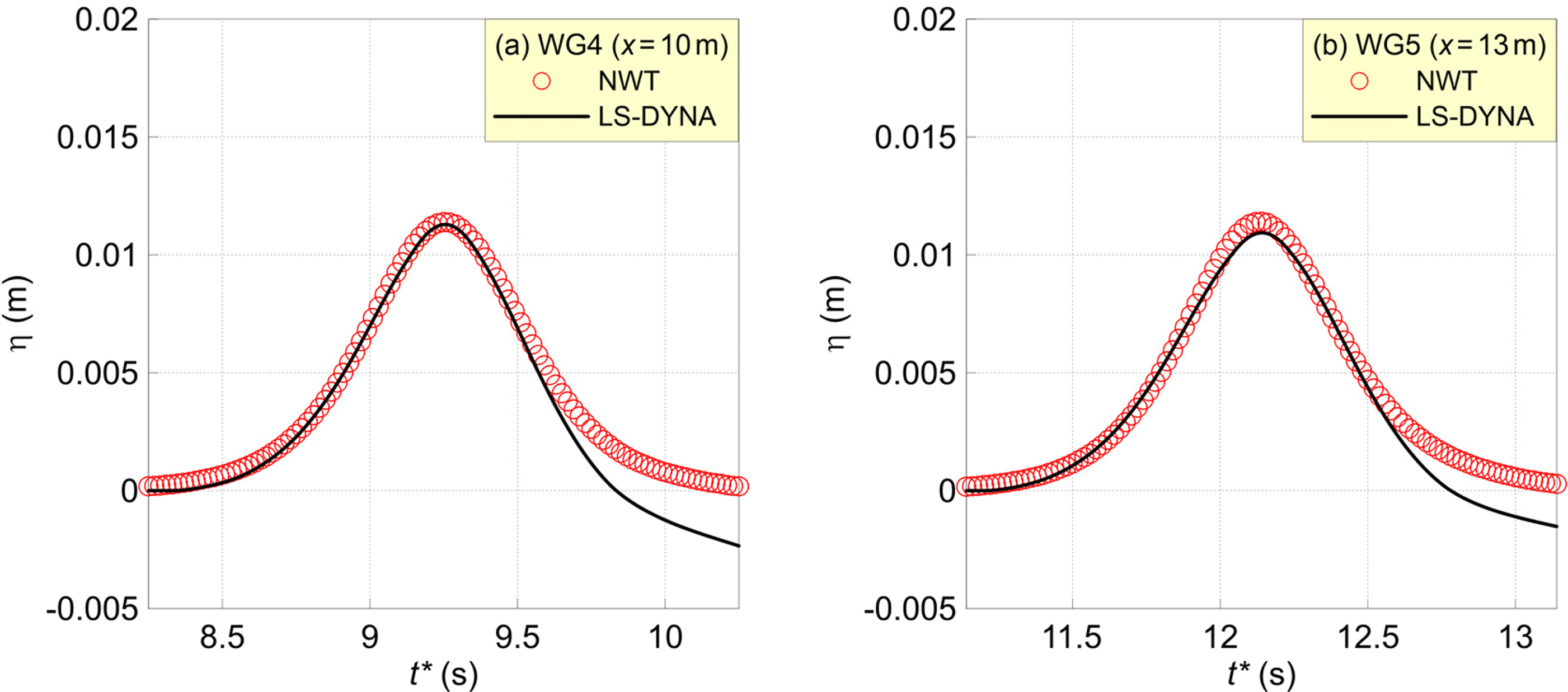
Fig. 11 presents a comparison of the NWT’s computed waveform, which considers the stable/steady state of the landside tsunami in which nonlinearity and dispersion are balanced, including the LS-DYNA waveform that was generated, propagated, and deformed by the falling object. Fig. 11(a) represents the time-domain waveform at WG4 (x = 10 m) near the wave source, while (b) is the time-domain waveform at WG5 (x = 13 m), which represents the propagation process. Here, the red circles represent the NWT computation results, while the black solid lines depict the LS-DYNA computational results.
The NWT water surface waveforms generated based on the approximation theory were very similar to the theoretical solitary wave and exhibited a smooth distribution. Furthermore, it can be observed that almost no deformation occurred owing to the stability of the water surface waveform in the solitary wave propagation process. In the LS-DYNA calculation results, the landslide tsunami was not in a 100% steady state; therefore, the wave height decreased slightly, while the waveform became slightly wider as it propagated. Therefore, at WG5 (x = 13 m), the NWT simulation’s wave height was slightly higher than that of LS-DYNA.
3.4.2 Flow velocity
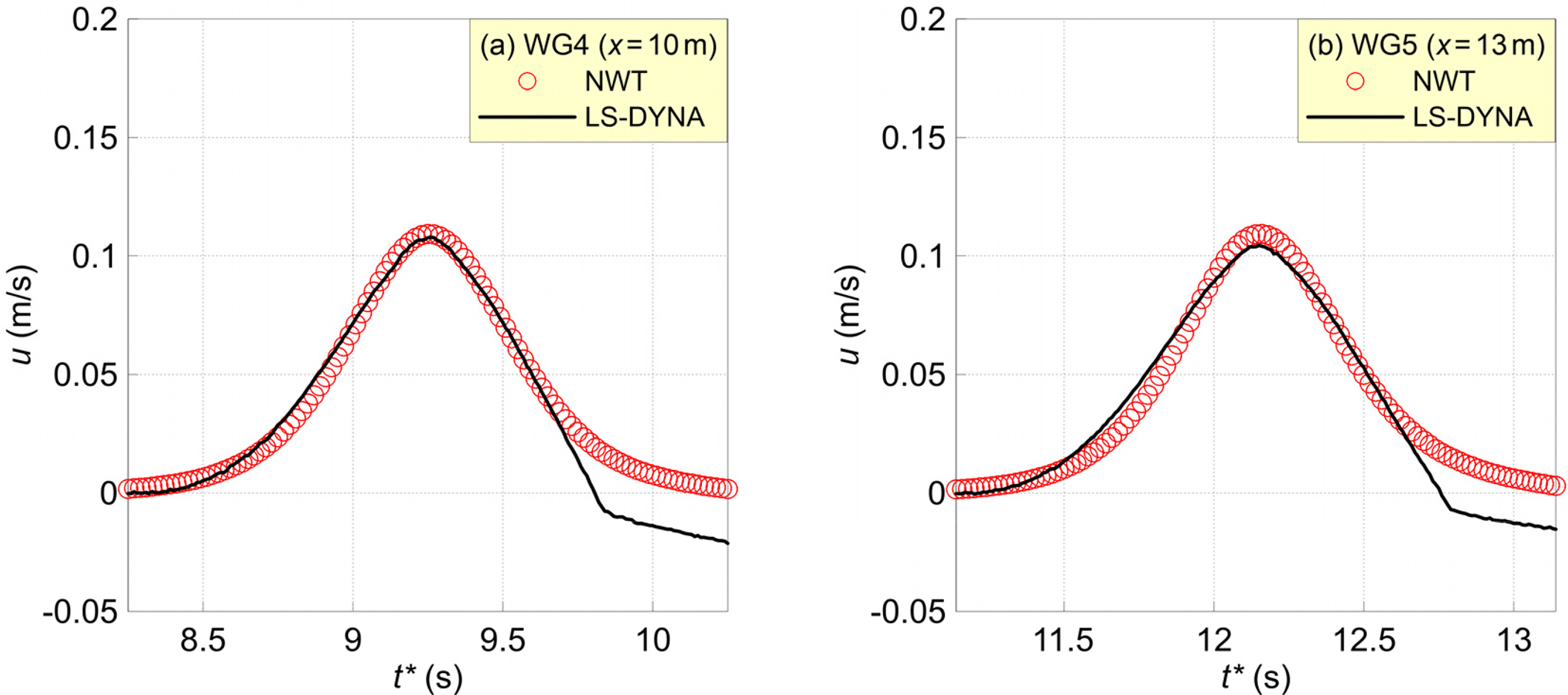
In the previous analysis, it was determined that the flow velocity of the LS-DYNA landslide tsunami became similar to the solitary wave at WG3 (x = 9.3 m). Figs. 12 and 13 present the horizontal and vertical flow velocity distributions at WG4 (x = 10 m) and WG5 (x = 13 m), respectively, comparing them with the NWT simulation results that adopt the solitary wave approximation theory.
Because the solitary wave approximation theory values are entered directly at the wave source, the NWT’s horizontal and vertical flow velocity distributions are almost the same as the theoretical solitary wave. If the flow velocities calculated in LS-DYNA and NWT are compared, their distributions are almost the same, except for the difference that occurs because the horizontal flow velocity of LS-DYNA’s landslide tsunami is asymmetrical. Regarding the vertical flow velocities, LS-DYNA’s computed values are slightly larger than those of NWT; however, there is a higher degree of agreement than in the case of the water surface waveforms and horizontal flow velocities.
3.4.3 Maximum wave pressure
The wave pressure that acts upon the vertical wall at x = 15 m and the water surface waveform in front of it are presented in Fig. 14, to compare LS-DYNA’s landslide tsunami and NWT computational results. Fig. 14(a) is the water surface waveform in front of the vertical wall, while Fig. 14(b) presents the maximum wave pressure acting on the vertical wall.
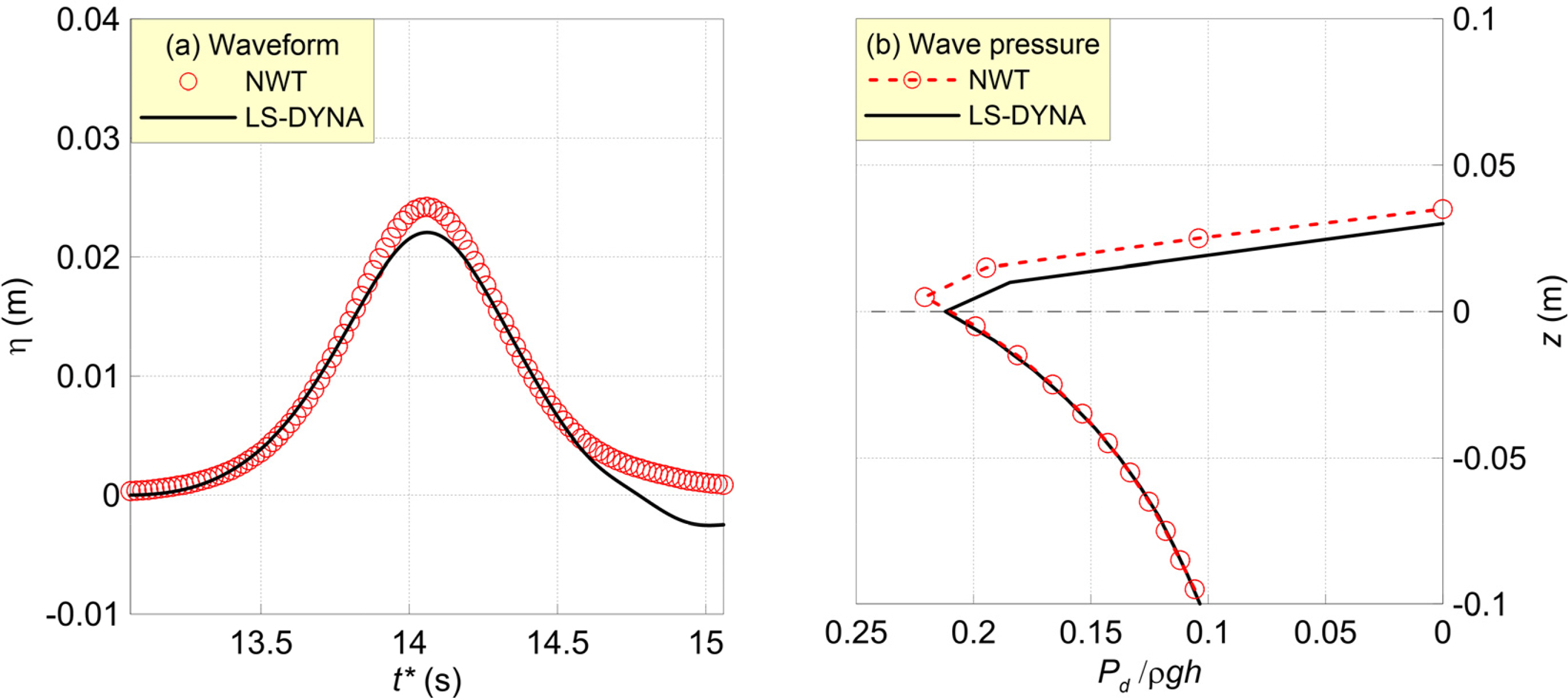
Comparisons of (a) time-domain waveform and (b) dimensionless wave pressure calculated by LS-DYNA and NWT
The wave height of the NWT’s solitary wave did not decrease during the propagation process; hence, its wave height increases in front of the vertical wall was greater than that of LS-DYNA. Consequently, the maximum wave pressure acting on the vertical wall was also slightly larger in the case of the NWT’s solitary wave, compared to LS-DYNA’s landslide tsunami.
In general, the LS-DYNA landslide tsunami analysis results and NWT solitary wave analysis results indicate that the hydraulic phenomena are slightly overestimated when solitary waves are created in the NWT, as compared to LS-DYNA. However, the two numerical analysis results did not exhibit a significant difference, and their water surface waveforms, flow velocities, and maximum wave pressure distributions were very similar.
4. Conclusions
This study adopted LS-DYNA and an NWT to analyze the generation and propagation properties of landslide tsunamis. The main results that were obtained via these two numerical analyses are described below.
A review and comparison with existing experimental results on landslide tsunamis verified the effectiveness and validity of LS-DYNA.
Via the LS-DYNA analysis, it was possible to understand the generation mechanism of landslide tsunamis caused by falling objects, and even the air inflow phenomena found in hydraulic model experiments (Monaghan and Kos, 2000) were optimally reproduced.
At the beginning of the landslide tsunami generation in LS-DYNA, the tsunami was narrower than a solitary waveform, while the horizontal and vertical flow velocities were larger; however, as the tsunami propagated, the wave height and flow velocities decreased, and the tsunami became similar to a solitary wave.
In a comparison of the analysis results from LS-DYNA and NWT, which considers the region that is 9.3 m away from the falling object where the landslide tsunami enters an almost stable/steady-state, the NWT results were slightly overestimated because a high-wave reduction did not occur during the propagation process; however, the water surface waveform, flow velocity, and maximum wave pressure distribution were similar.
To analyze the nonlinear interactions between fluids and structures during a landslide tsunami’s generation process or analyze the hydraulic characteristics of adjacent regions, numerical analyses such as LS-DYNA are certainly necessary. However, when a landslide tsunami propagates beyond a certain distance and enters a stable/ steady state in which nonlinearity and dispersion are balanced, its hydraulic characteristics can only be sufficiently analyzed via an NWT analysis, which can create solitary waves. In addition, it has been determined that NWT analysis is advantageous in terms of time and money because it has a smaller computational burden than LS-DYNA and incurs no additional usage fee.
Notes
Woo-Dong Lee serves as an editor of Journal of Ocean Engineering and Technology, but has no role in the decision to publish this article. No potential conflict of interest relevant to this article was reported.
This work was supported by the National Research Foundation of Korea(NRF) grant funded by the Korea government(MSIT) (No. NRF-2021R1A2C4002665).


