Survey of Acoustic Frequency Use for Underwater Acoustic Cognitive Technology
Article information

Abstract
The available underwater acoustic spectrum is limited. Therefore, it is imperative to avoid frequency interference from overlapping frequencies of underwater acoustic equipment (UAE) for the co-existence of the UAE. Cognitive technology that senses idle spectrum and actively avoids frequency interference is an efficient method to facilitate the collision-free operation of multiple UAE with overlapping frequencies. Cognitive technology is adopted to identify the frequency usage of UAE to apply cognitive technology. To this end, we investigated two principle underwater acoustic sources: UAE and marine animals. The UAE is classified into five types: underwater acoustic modem, acoustic positioning system, multi-beam echo-sounder, side-scan sonar, and sub-bottom profiler. We analyzed the parameters of the frequency band, directivity, range, and depth, which play a critical role in the design of underwater acoustic cognitive technology. Moreover, the frequency band of several marine species was also examined. The mid-frequency band from 10 - 40 kHz was found to be the busiest. Lastly, this study provides useful insights into the design of underwater acoustic cognitive technologies, where it is essential to avoid interference among the UAE in this mid-frequency band.
1. Introduction
The growing interest in marine space has highlighted the significance of marine resource development, maritime exploration, and maritime defense. Consequently, underwater exploratory missions are becoming more complex and diverse. Accordingly, various mission-specific underwater acoustic equipment (UAE) has been developed, including underwater navigation, underwater mapping exploration, underwater image acquisition, marine physical quantity measurement, and data exchange. Depending on the operating characteristics and required functions, the frequency band used by such UAE vary. However, because there is no permit or restriction on frequency use in open frequency bands, such as those underwater, a variety of acoustic equipment is mixed, causing the issue of frequency overlaps between artificial interferences. Acoustic communication systems and acoustic positioning systems are integral acoustic equipment, particularly in systems equipped with sonar equipment for seabed mapping or image acquisition, such as unmanned surface vehicles (USVs), autonomous surface vehicles (ASVs), autonomous underwater vehicle (AUVs), and remotely operated vehicles (ROVs). When such acoustic equipment operates simultaneously, signal interferences occur between communication, navigation, and sonar devices. In addition to man-made acoustic interferences, underwater marine animals cause natural acoustic interferences. For example, some marine mammals use sound waves to communicate between themselves and analyze reflected sound waves to avoid obstacles and determine the proceeding direction (echolocation), and when these signals interfere with artificial signals, it can cause severe damage. There have been reports of cases where interferences between artificial signals produced from equipment and naturally occurring signals have led to dolphins colliding with ships and getting beached after losing their heading, leading to the destruction of marine life.
Numerous cases and studies are underway to solve the aforementioned problems caused by acoustic signal interferences. Kongsberg’s K-Sync equipment (Kongsberg, 2020) allows the user to set signal generating time, cycles, and intervals for each piece of equipment when operating different acoustic equipment. It prevents different pieces of equipment from generating signals simultaneously to avoid signal interferences. Studies have been conducted to investigate the frequency bands of marine mammals to avoid natural acoustic interferences (Ferguson and Cleary, 2001; Richardson et al., 2013) and predict the frequencies used by marine animals to prevent signal interference (Moore et al., 2012; Cheng 2017). The communication and network fields are leading the research on underwater signal interference avoidance techniques, and studies have been actively conducted to avoid interferences by applying multiple media access control methods and using orthogonal times, frequencies, codes, and phases between signals, or avoid signal interferences using a directional antenna-applied transceiving method and an idle listening method before transmission (Ali et al., 2020; Chitre et al., 2008; Goyal et al., 2019; Murad et al., 2015; Jiang 2008; Zolich et al., 2019).
As the use of UAE increases, their frequencies also increase, making underwater frequency bands increasingly chaotic. Therefore, network technology for frequency interference avoidance also becomes increasingly significant. Network technology is adopted to avoid signal interferences while using the limited underwater frequency bands more efficiently. The process of avoiding signal interferences requires the application of underwater cognitive acoustic network technology to actively avoid the occupied frequency bands by detecting idle underwater frequency bands and dynamically allocating frequency bands (Li et al., 2016; Luo et al., 2014; Luo et al., 2016a; Luo et al., 2016b; Cheng et al., 2017). To apply the cognitive network technology, The application of the cognitive network technology requires recognizing which underwater frequency bands are available temporally and spatially, which prerequisites the investigation of underwater acoustic frequency usage status.
In this study, we investigate and analyze UAE that uses sound waves and marine animals that communicate using sound waves. Moreover, we summarize and describe the main frequency bands used by marine animals and the frequency usages of commercial products for distinct UAE to use them as basic data for underwater wireless cognitive network technology. The investigated and analyzed acoustic equipment is classified according to the model of each manufacturer based on the purpose of use, and devices used primarily for marine exploration and investigation are chosen. The chosen equipment types include an underwater acoustic modem, acoustic positioning system, multi-beam echo-sounder (MBES), side-scan sonar (SSS), and sub-bottom profiler (SBP). We describe the equipment operating characteristics according to the equipment type to determine the temporal and spatial availability of frequency bands and introduce the required specifications based on the described equipment characteristics. In this study, the frequency bands of the marine equipment and marine animals are investigated and illustrated in graphs, and the major frequency bands of each piece of equipment and marine animals are combined and illustrated in graphs for comparison and analysis.
This study is organized as follows: In Section 2, status of underwater acoustic equipment frequencies is summarized and plotted. In Section 3, the frequencies used by marine animals are analyzed and summarized. Lastly, Section 4 provides the conclusion of this study.
2. Status of Underwater Acoustic Equipment Frequencies
2.1 Underwater Acoustic Modems
Table 1 lists the specifications of product models for each manufacturer of commercial underwater acoustic telemetry modems. The commercial underwater acoustic telemetry modems use a frequency band from 2.5–180 kHz; however, depending on the transmission distance, the frequency range varies. A frequency band of 20–180 kHz is used in a communication range of 1 km or less, 7.5–78 kHz in a communication range of 1–5 km, 7–31 kHz in a communication range of 5–10 km, and 2.5–31 kHz in a communication range of over 10 km. As shown in Fig. 1, the primary frequency bands of commercial acoustic telemetry modems are concentrated in the 10–30 kHz band because underwater acoustic signals propagate most smoothly in this band. As shown in Fig. 2, the communication range of the commercial acoustic telemetry modems is mostly around 5 km, and a small number of long-range acoustic telemetry models of 10 km or longer exists. Remarkably, Thales TUMM-6 has a communication range of 37 km. Fig. 3 illustrates a graph for the operating depths of the commercial underwater acoustic telemetry modems distributed randomly according to the product characteristics and purpose, and it can be seen that a maximum operating depth of 10 km is achievable.

Specifications of underwater acoustic telemetry modems (Zia et al., 2021)
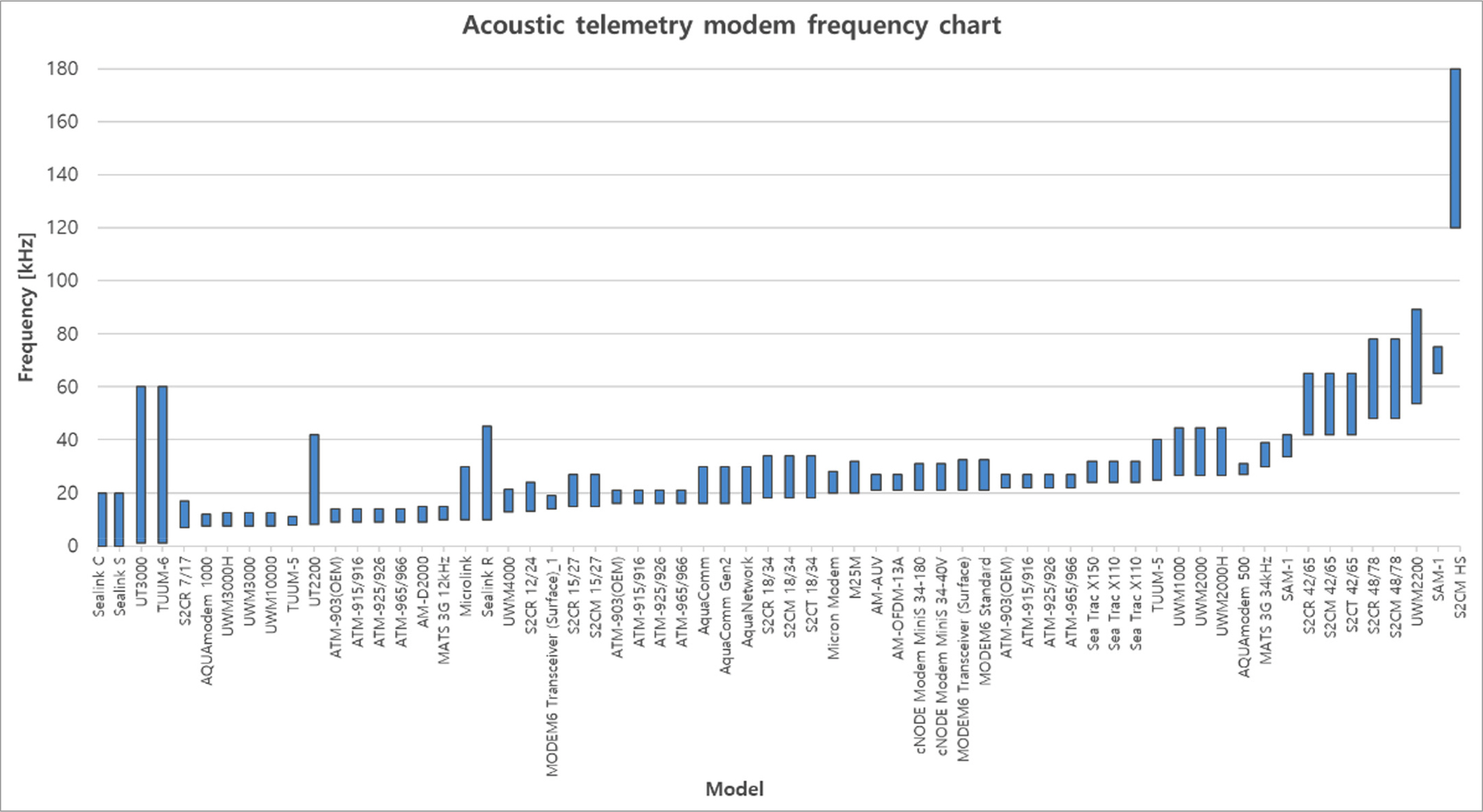
Acoustic telemetry modem frequency chart

Acoustic telemetry modem communication range

Acoustic telemetry modem operating depth
2.2 Acoustic Positioning Systems
An acoustic positioning system tracks the relative position of a vehicle being tracked. Generally, an underwater acoustic sensor, which becomes a baseline, is installed on the ship or seabed, and after installing underwater acoustic sensors for response (transponders) on the tracking-target vehicle, the acoustic signals are transmitted and received between the underwater acoustic sensors at both ends. The system can be linked to a satellite navigation system to track the absolute position of an object.
Acoustic positioning systems are essential for tracking the position of underwater vehicles, such as underwater robots, and, based on the tracking method, acoustic positioning systems are classified as long baseline (LBL), short baseline (SBL), and ultrashort baseline (USBL). LBL refers to estimating the position by installing the baseline at a fixed position on the seabed and measuring the slant range from the widely spaced transponder. SBL refers to estimating the position by installing the baseline at a fixed position on the seabed and measuring the relative arrival time from three or more transponders installed on a ship (Vickery, 1998). USBL involves estimating the position by installing the baseline on a ship or an underwater vehicle that performs the role of the mother ship and measuring the relative phase of the acoustic signals received using the array sensors embedded in the single transponder (Soppet, 2011).
Table 2 lists the specifications of product models for different acoustic positioning system manufacturers. Numerous acoustic positioning system models use SSBL, USBL, and LBL simultaneously, and many models also use USBL and acoustic telemetry functions simultaneously. In Table 2, the field of view indicates the angle for the zone where the acoustic positioning system can operate. In an acoustic positioning system, multiple transducers are structured in an array, producing acoustic signals, and the combination of the beam pattern of each transducer signal determines the system’s operating range. The field of view value―the beamwidth of the combined acoustic signals―is the half-power beamwidth of the acoustic signals in general and indicates the beamwidth from the maximum acoustic strength to an acoustic signal strength of −3 dB lower. Fig. 4 illustrates the frequency band distribution of the acoustic positioning systems, and similar to the underwater acoustic telemetry modems, the primary frequency bands are concentrated between 10–30 kHz. As depicted in Fig. 5, the acoustic systems have various operating ranges from 300–11000 m.

Specifications of acoustic positioning systems
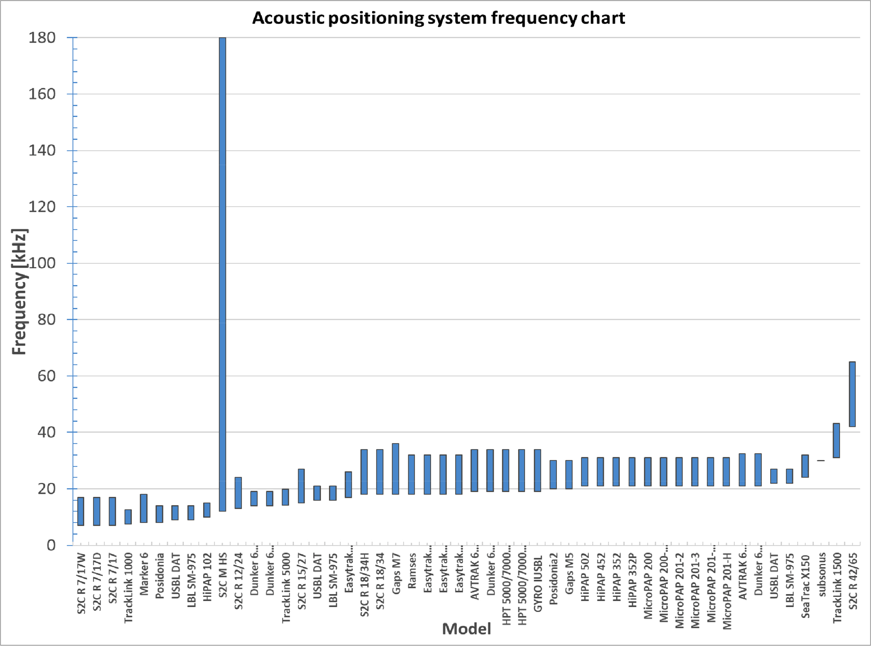
Acoustic positioning system frequency chart
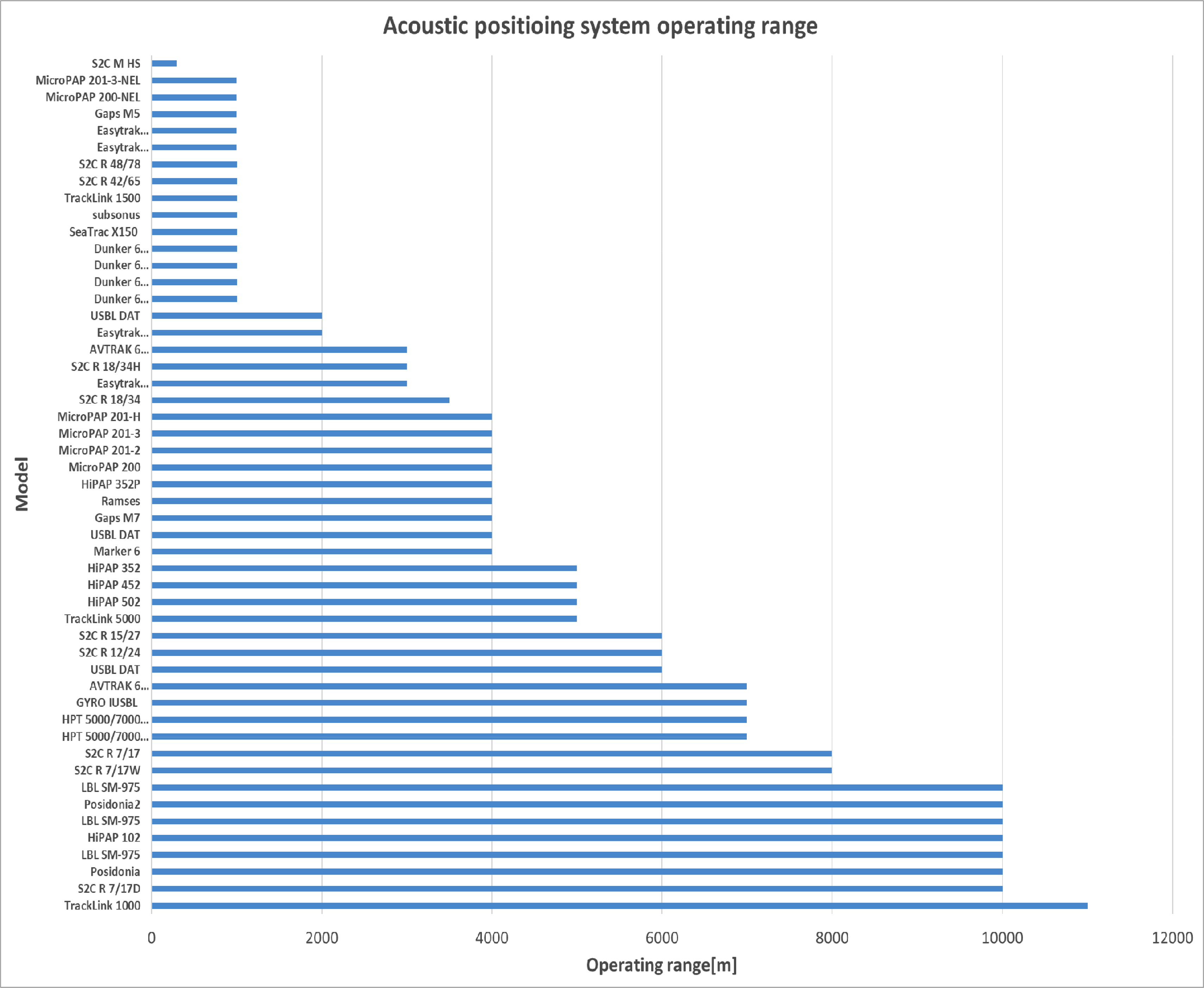
Acoustic positioning system operating depth
2.3 Multi Beam Echo-Sounders (MBES)
MBES is a system that emits hundreds of sound waves simultaneously and receives the reflected waves from the seabed to create an automated topographical map on a computer. It measures the distance of an obstacle at each angle. MBES is used in exploring seabed topography, searching for sunken ships, identifying submarine geological characteristics, installing and repairing submarine pipes and cables, securing views of underwater vehicles, and other underwater operations.
Table 3 lists the specifications of product models for each commercial MBES manufacturer. In the beamwidth of the sound wave generated by MBES, “x” indicates the horizontal x vertical beamwidth, which ranges from 0.5°–5°. In the beamwidth column in Table 3, the listed beamwidth values, such as 1°, 2°, and 3°, can be selectively used according to the resolution required in the corresponding frequency band, and, as the beamwidth becomes narrower, the resolution increases. However, the number of sound waves generated by the MBES also increases. Therefore, the beamwidth increases in the low-frequency band and decreases in the high-frequency band. As shown in Fig. 6, 10–1000 kHz is used as the frequency band of MBES, and the primary frequency bands used are between 200–500 kHz, which are high-frequency bands compared to those of the communication or navigation systems. Fig. 7 illustrates the operating depths of MBES, which are distributed variously from 100–11000 m.

Specifications of MBESs
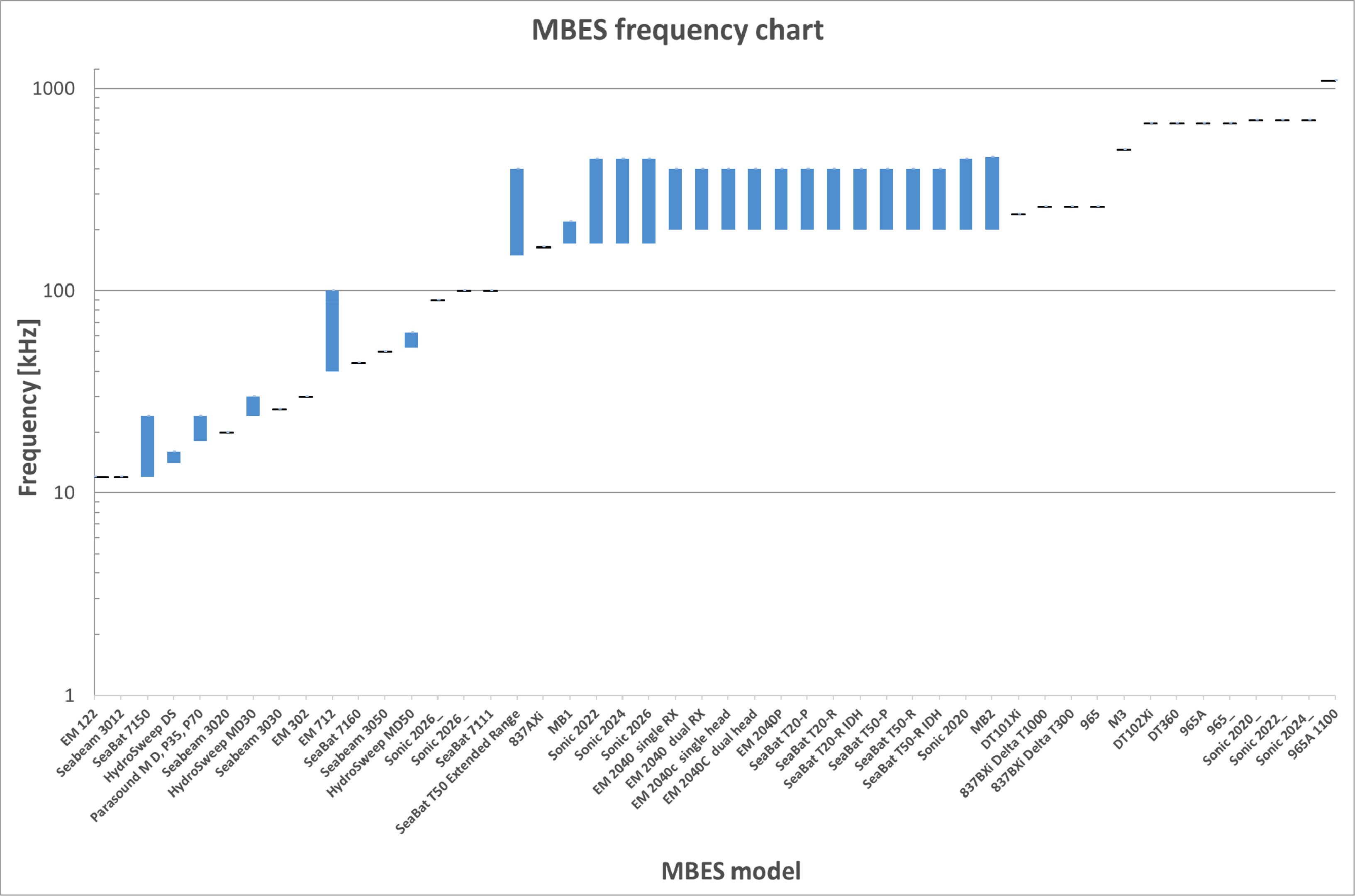
MBES frequency chart
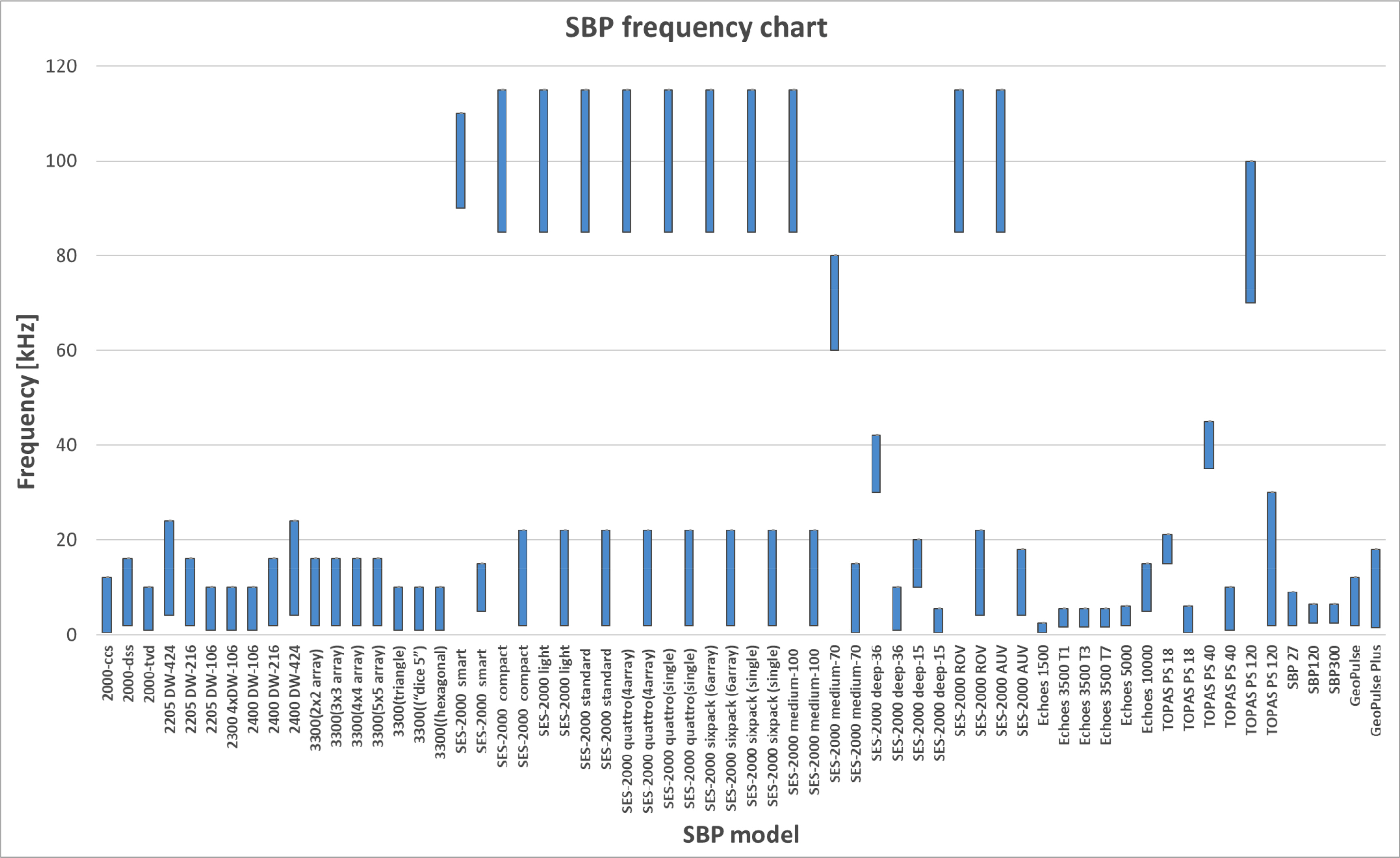
SBP frequency chart

MBES immersion depth
2.4 Side-Scan Sonars (SSS)
SSS systems use a towing fish to generate sound waves in the left and right directions underwater and receive the reflected waves to create an automated topographic map on a computer. It measures the distance of an obstacle at each angle. Occasionally, SSS systems simultaneously perform the bathymetry function of measuring the underwater depth in the sea; examples include EdgeTech’s 6205 bath model and Sonardyne’s SOLSTICE model. Table 4 lists the specifications of product models for each SSS system manufacturer. SSS systems use dual or triple frequency bands simultaneously. In Table 4, “230/540 with 540 kHz Bath” shown for the 6205 bath model means that SSS and bathymetry functions are performed simultaneously by using dual-frequency bands of 230 and 540 kHz for SSS and a frequency band of 540 kHz for bathymetry. As illustrated in Fig. 8, the frequency bands of SSS are distributed between 75–1600 kHz, and the primary frequency bands are concentrated between 100–1000 kHz. The horizontal beamwidth of SSS is distributed between 0.26°–1.8°, and the vertical beamwidth is distributed between 30°–90°. Fig. 9 illustrates the operating ranges of SSS, and SSS systems operate in various ranges from 35–1250 m.

Specifications of SSSs
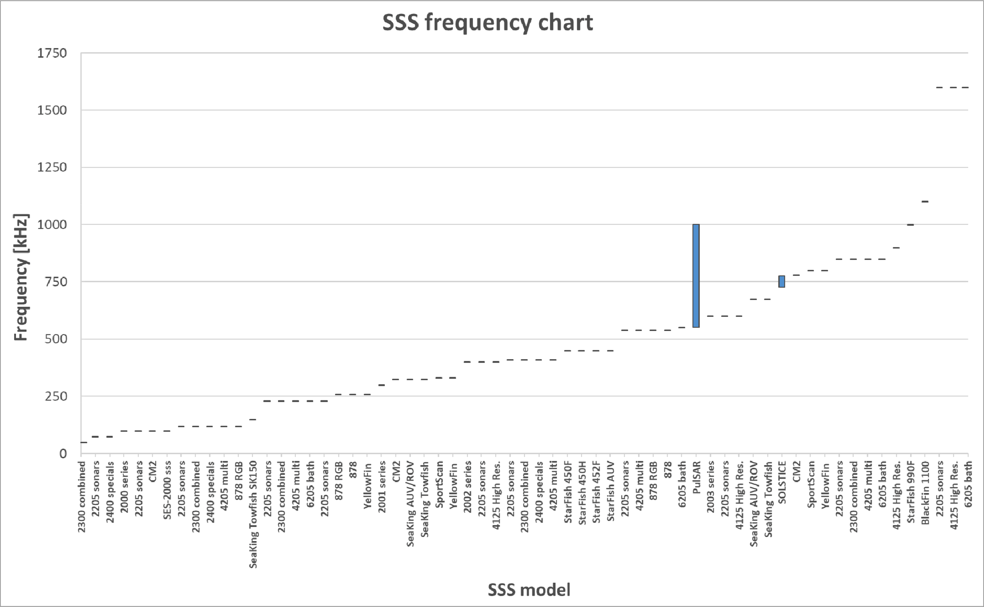
SSS frequency chart
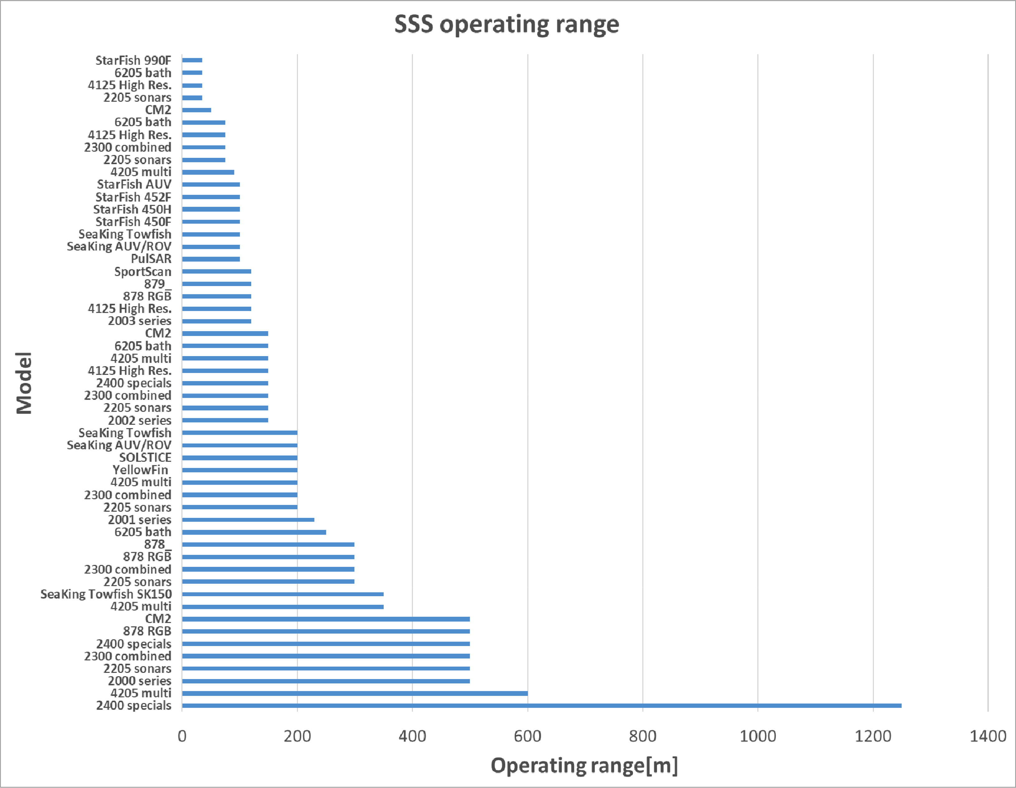
SSS operating range
2.5 Sub-Bottom Profilers (SBP)
SBP systems generate low-frequency sound waves to a submerged-body underwater and receive the reflected waves from the seabed to create a topographic map and sub-bottom profiles on a computer. It is used to investigate submerged artifacts, explore buried naval mines, and investigate marine and inland water geology, the conditions of buried submarine pipelines and cables, and marine and inland water sub-bottom profiles.
Table 5 lists the specifications of product models for each SBP manufacturer. As shown in Fig. 10, SBP uses the primary frequency band (generally 90–110 kHz) and the secondary frequency band (≤ 30 kHz) simultaneously. The frequency bands are lower than 120 kHz, which is comparatively lower than those of MBES or SSS. Moreover, SBP produces the loudest noise among the acoustic equipment, which may interfere with other acoustic equipment. Fig. 11 illustrates the operating depths of SBP, which are distributed variously between 30–11000 m.

Specifications of SBPs
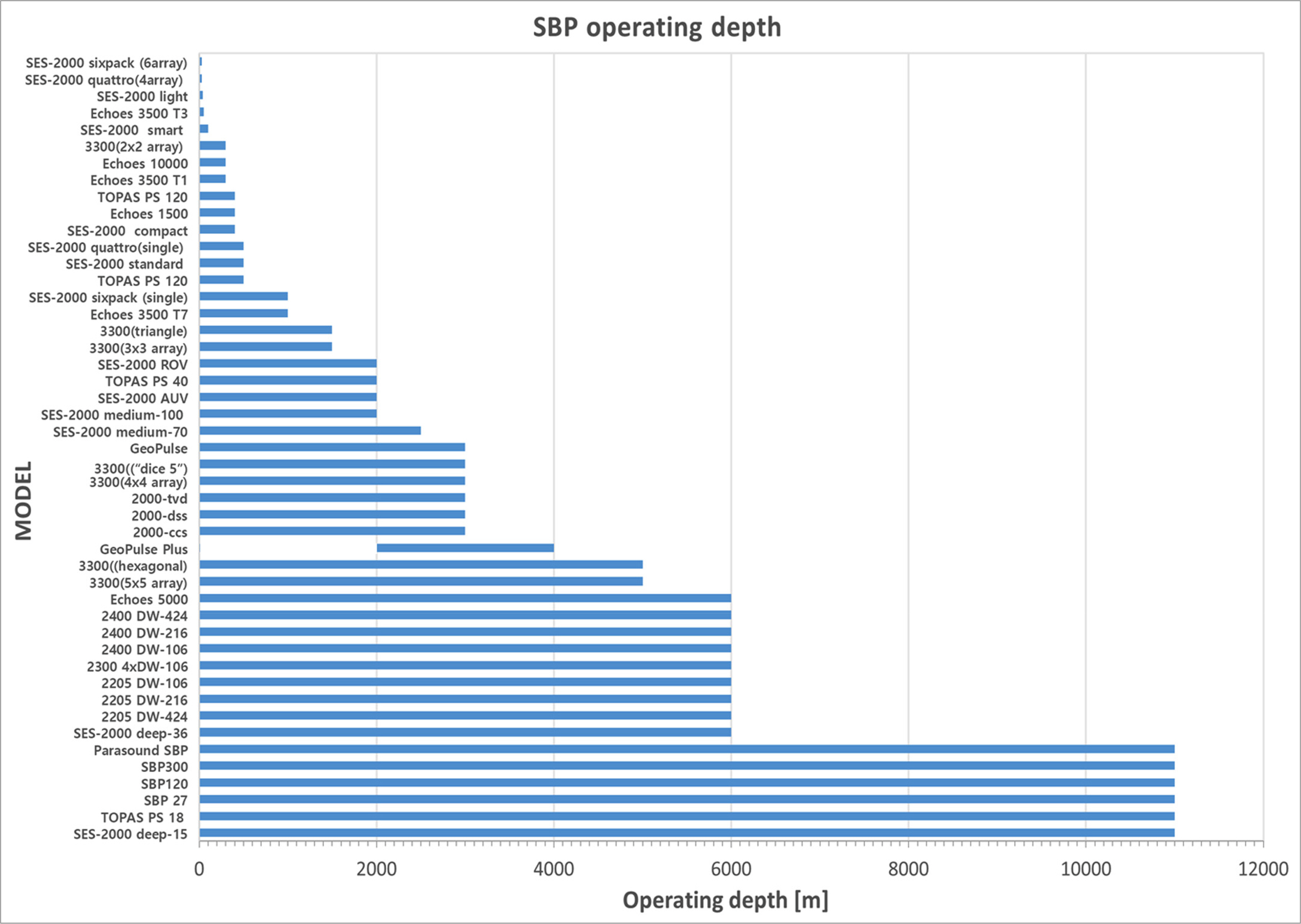
SBP operating depth
3. Frequencies Used by Marine Animals
The spatial characteristics of major habits or ecological characteristics of marine animals should be considered to determine whether the frequency bands of marine animals using sound waves are available spatiotemporally. However, it is skipped in this study because it is outside the research scope, and we will only deal with the status of the frequency bands used by marine animals. Table 6 summarizes the frequency ranges and the dominant frequency ranges used by marine animals that communicate using sound waves. As shown in Fig. 12, underwater marine animals generate frequencies in the 0.01–170 kHz band, and the dominant frequencies are below 20 kHz. These frequencies match the primary frequency bands generated by UAE, such as underwater acoustic modems and acoustic positioning systems, which may cause communication collisions between acoustic equipment and marine animals.
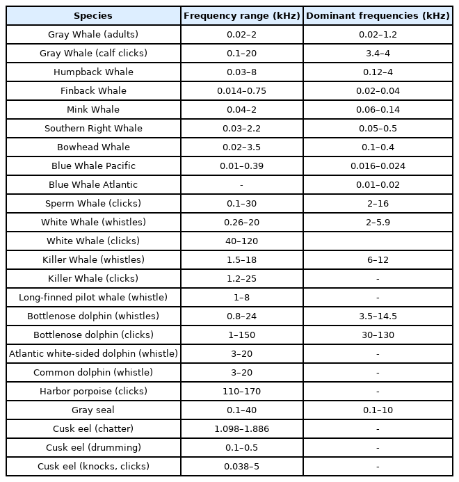
Frequencies used by marine animals (National Research Council, 2000)

Marine animal sound frequency chart
4. Conclusion
In this study, we investigated and analyzed the frequency bands used by commercial products for each manufacturer of UAE according to the purpose of use. Moreover, we also investigated the frequency bands used by marine animals that communicate using sound waves. Fig. 13 illustrates a graph that summarizes and illustrates the primary frequency bands used by each piece of equipment and the dominant frequency bands of marine animals. The frequency bands illustrated in Fig. 13 are the frequency bands of equipment and marine animals that are within 80% of the minimum and maximum frequency range for each marine animal and acoustic equipment type investigated. As shown in Fig. 13, the frequencies overlap most in the mid-frequency range (10–40 kHz) because both acoustic equipment and marine animals use these frequencies. In the case of acoustic telemetry modems and acoustic positioning systems, the primary frequency bands are almost identical and overlap in a range of 10–30 kHz, meaning that a collision avoidance method is required to prevent signal interference. The frequency band of MBES is a high-frequency band compared to that of the above equipment and is concentrated between 50–500 kHz. The frequency band of SSS is primarily distributed between 150–850 kHz, and the same model can use dual or triple frequency bands simultaneously. SBP uses the primary frequency band (60–110 kHz) and the secondary frequency band (45 kHz or lower) simultaneously and produces the largest noise among acoustic equipment, which increases the likelihood of causing interferences in other acoustic equipment. Meanwhile, marine animals primarily generate acoustic signals in the range of 0.1–20 kHz, and measures should be in place to avoid frequency overlaps with the secondary frequency bands of acoustic modems, acoustic positioning systems, and SBP. Moreover, the frequency bands of the analyzed acoustic equipment and marine animals can be used as reference data to avoid signal interferences when operating multiple pieces of UAE simultaneously. Finally, the frequency bands of UAE and marine animals can be used to develop technology for underwater spectral sensing, sharing, and frequency band determination in underwater acoustic cognitive technology, where it is crucial to avoid underwater signal interferences.
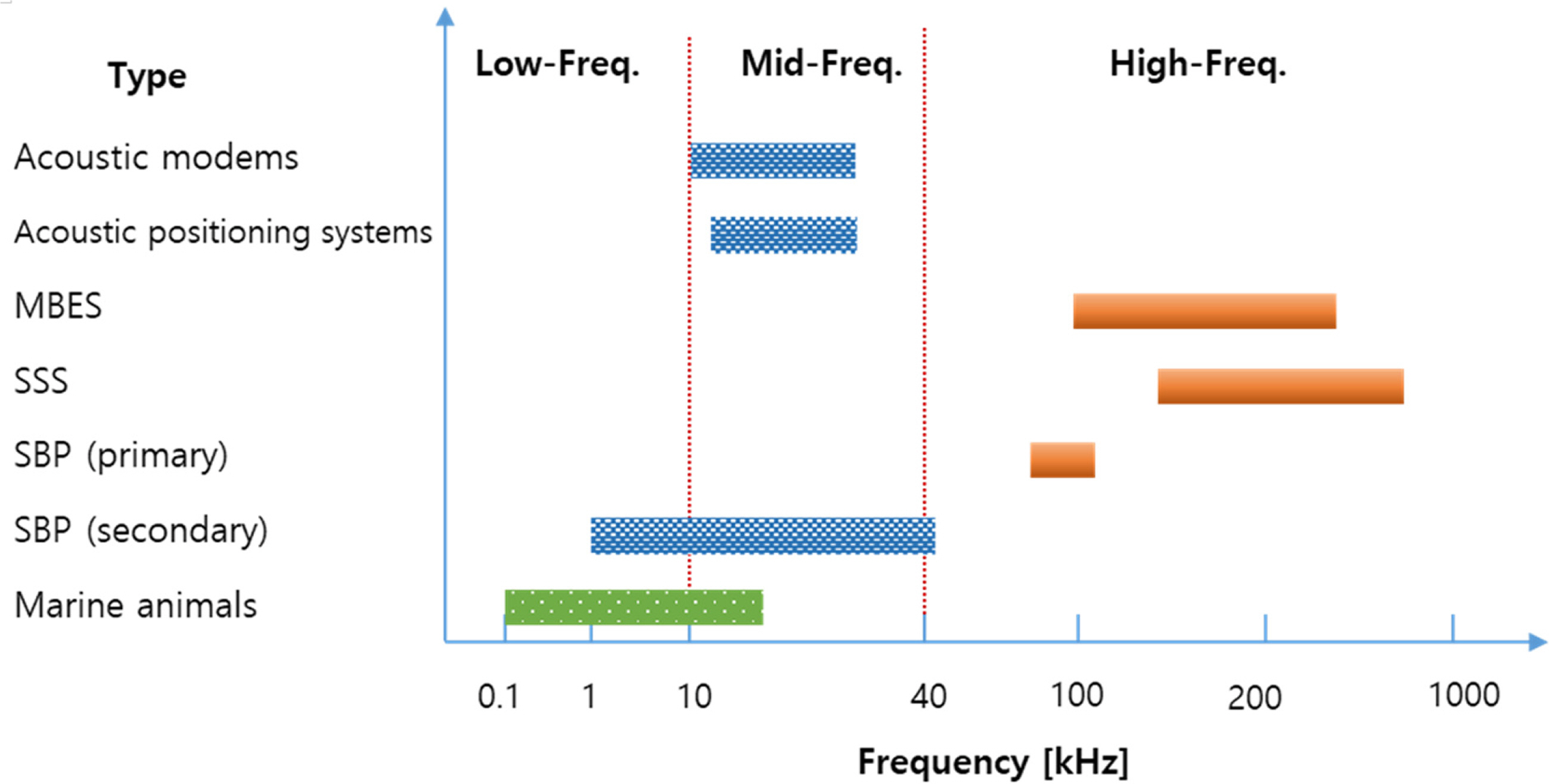
The frequency bands for the acoustic equipment and marineanimals
Notes
This research was supported by a grant from the Endowment Project of “Development of core technology for cooperative navigation of multiple marine robots and underwater wireless cognitive network” funded by the Korea Research Institute of Ships and Ocean engineering (PES4370).