Effect of Internal Fluid Resonance on the Performance of a Floating OWC Device
Article information

Abstract
In the present study, the performance of a floating oscillating water column (OWC) device has been studied in regular waves. The OWC model has the shape of a hollow cylinder. The linear potential theory is assumed, and a matched eigenfunction expansion method(MEEM) is applied for solving the diffraction and radiation problems. The radiation problem involves the radiation of waves by the heaving motion of a floating OWC device and the oscillating pressure in the air chamber. The characteristics of the exciting forces, hydrodynamic forces, flow rate, air pressure in the chamber, and heave motion response are investigated with various system parameters, such as the inner radius, draft of an OWC, and turbine constant. The efficiency of a floating OWC device is estimated in connection with the extracted wave power and capture width. Specifically, the piston-mode resonance in an internal fluid region plays an important role in the performance of a floating OWC device, along with the heave motion resonance. The developed prediction tool will help determine the various design parameters affecting the performance of a floating OWC device in waves.
1. Introduction
The utilization of ocean energy has become an important and urgent issue owing to its abundance and value as clean energy. In particular, the development of new energy sources is inevitably necessary to respond to the carbon emission trading system. However, the commercialization of ocean energy, that has economic feasibility, has not yet been realized because of expensive installation and power transmission costs along with irregularity of the ocean environment. Several efforts have been being taken to resolve these inherent demerits; these efforts include combined power generation, where at least two power sources among wind, wave, and current power are used for a single support structure, direct consumption of generated power at the site, and storing the generated power into the battery without transmission to land.
The technologies related to wave power generation have been developed since the 1980s mainly in Europe and Japan, where wave energy sources are abundant. Several devices have been suggested for wave energy generation, which are near the commercialization stage. Existing wave energy converters (WECs) are categorized as attenuator, point-absorber, and terminator types, based on the position of the WEC with respect to the direction of incident wave propagation. The attenuator type composes of multiple WECs connected parallel to the direction of incident wave propagation; thus electrical energy is generated from the relative motion of converters at the joints by the action of the waves. The Pelamis is a well-known attenuator WEC. The point-absorber type can generate electricity regardless of the direction of incident wave propagation. Particularly, it enhances energy extraction efficiency by amplifying the heave motion of the WEC through resonance with the incident wave with a low energy density. Power buoy and Wavebob are typical point-absorber WEC. Lastly, the terminator type has a WEC positioned in the direction perpendicular to the propagation direction of the incident wave to extract wave energy. Examples of this type include Salter’s duck WEC and dual-functional WEC that has a function of a breakwater.
For converting wave energy into electrical energy, the wave energy is modified through two-step transformations. The first step transformation converts the wave energy into the mechanical energy such as the kinetic and potential energy. These transformation devices are called the movable body, oscillating water column (OWC), and overtopping type (Falcão, 2010). In particular, an OWC device is presently installed and operated in several regions, as the technology has been stabilized. Moreover, the maintenance cost is also fairly low due to a small number of moving machinery parts. The OWC has a enclosed air chamber positioned on top of a supporting structure (fixed, floating) having an open bottom. The free-surface inside the air chamber oscillates up and down due to incident waves, thus inducing airflow due to pressure difference between inside and outside of the chamber; the airflow rotates a turbine located on a passage outside the air chamber; in the final stage, electricity is produced from the generator. The Wells turbine and impulse turbine are used as a second step transformation device that converts the flow energy of air into electrical energy, changing bidirectional airflow into unidirectional turbine’s rotation. The OWC device was first proposed by Masuda (1979); since then, it has been extensively studied by numerous researchers through analytical, numerical, and experimental approaches. The OWC devices are installed in many regions throughout the world, and the Land Installed Marine Powered Energy Transformer (LIMPET) installed in Scotland in 2000 is known as the world’s first wave power generation system that is operated through connection with an existing power grid (Heath et al., 2000). The Korea Research Institute of Ships and Ocean Engineering (KRISO) has recently constructed a real-sea pilot plant that houses fixed type OWC (31.2 × 37.0 m) at water depth 15 m near Chagwido Island, Jeju, and is currently conducting tests to evaluate its performance and efficiency.
To analyze the performance of the fixed and floating OWC device, Evans and Porter (1995, 1997) calculated the wave-energy absorption efficiency by solving the radiation problem due to oscillating pressure in the air chamber and the diffraction problem of a fixed OWC in waves. Mavrakos (1985, 1988) analyzed the diffraction and radiation problems of a hollow cylinder using a matched eigenfunction expansion method (MEEM). Sioris and Memos (1999) performed numerical analysis using the Green’s function method and obtained results that were different from those of Mavrakos (1985, 1988). Cho (2002) used a MEEM to analyze the performance of a fixed cylindrical OWC device. Hong et al. (2004) and Suzuki et al. (2004) numerically analyzed the performance of a floating OWC device using a higher-order boundary element method. Mavrakos and Konispoliatis (2012) used a MEEM to theoretically calculate the extracted power and efficiency of a floating OWC device. Bull (2015) investigated the motion responses and oscillating pressure in the air chambers of a Backward Bent Duct Buoy (BBDB), which belongs to the floating OWC, and an axisymmetric OWC considering the resonance of the internal fluid of an air chamber; they further examined the coupling effect between a floating OWC device and air pressure using a commercially available code WAMIT. Gomes et al. (2012, 2016) carried out systematic researches on the energy extraction performance of an axisymmetric floating OWC device. They replaced the surface of the internal fluid with a thin disk having no weight under the assumption that the size of an air chamber is smaller compared to the wavelength of incident waves and evaluated the extraction power of an OWC device from the relative heave motion between the floating OWC and disk. Regular waves were extended to irregular waves, and the optimization of design parameters was performed using an objective function. Park et al. (2018) evaluated the performance of an axisymmetric floating OWC device using a finite element method (FEM) under a linear potential theory. For considering the damping effects of power take-off, the nonlinear modified kinematic and dynamic free surface boundary conditions proposed by Koo et al. (2010) were linearized to be applied. Furthermore, Luo et al. (2014) applied computational fluid dynamics (CFD) codes for considering viscosity effects. They analyzed the coupling effect of the heave motion of a floating OWC device and oscillating air pressure using a commercially available code FLUENT, which is based on the Navier-Stokes equations.
In this study, the extracted wave power and absorption efficiency of a floating OWC device of a hollow cylinder shape has been extensively investigated in the frequency domain by extending the analytical tool developed by Bae and Cho (2013). Boundary value problems for the diffraction and radiation (heave motion of a floating OWC device, oscillating pressure in the air chamber) were formulated and analytically solved using a MEEM to obtain the hydrodynamic force as well as the flow rate of the internal fluid of the air chamber. Subsequently, the equation of the heave motion of a floating OWC coupled with oscillating pressure in the air chamber was formulated and solved; finally, the extracted wave power and capture width of the OWC device was calculated. Particularly, the piston-mode resonance of the internal fluid in the air chamber was intensively examined. Using the developed predictive tool, the effects of the shape (radius, draft, thickness, etc.) of a floating OWC device and turbine characteristics on the hydrodynamic loads, flow rate, oscillating air pressure, heave motion response, and extraction efficiency were clarified.
2. Mathematical Formulation
A floating OWC device consisting of a hollow cylindrical body with an inner radius b, outer radius a, draft d, and an air chamber with a height H is selected as a calculation model as shown in Fig. 1. The cylindrical coordinate system is introduced, in which the origin is set on the free surface, and the direction of the z-axis is set vertically upward. Air pressure inside the air chamber is expressed as the sum of atmospheric pressure Patm and oscillating pressure Pc(t) due to waves. The oscillating pressure is assumed to be constant inside the air chamber in space. When the incident wave exhibits a harmonic motion with a frequency ω, the velocity potential can be written by Φ(r,θ,z,t) = Re{ϕ(r,θ,z)e−iωt} under the assumption of a linear potential theory. The velocity potential ϕ(r,θ,z), which is a complex function, can be expressed as the sum of the scattering potential (ϕ1 ), i.e., the sum of incident potential (ϕ0) and diffracted potential (ϕD ), and the radiated potential (ϕ2 ) due to the heave motion of a floating OWC, and the radiated potential (ϕ3) due to oscillating air pressure in the chamber, as shown in Eq. (1). All motion modes are constrained, and only the heave motion is taken into consideration. Since the calculation model is axisymmetrical, the radiated potential is not associated with the θ-axis, unlike the scattered potential that is a function of (r,θ,z).
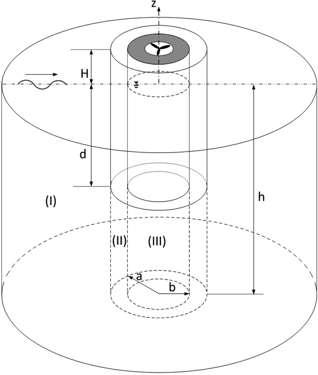
Schematic of a floating axisymmetric OWC wave energy converter
The velocity potential is determined by solving the boundary value problem of the scattering (j = 1) and radiation (j = 2,3) given above. The hydrodynamic force Fj(t)=Re{fje− iωt} in the vertical direction on a floating OWC and the flow rate (Qj(t)=Re{qje− iωt}) due to surface oscillation of interior fluid are expressed as follows.
If Eq. (1) is substituted in Eq. (3) in the same manner, the flow rate inside the air chamber can be calculated as follows.
2.1 Diffraction Problem
For applying a MEEM, the whole fluid region is divided into regions (I), (II), and (III) as shown in Fig. 1. Region (I) is defined as r≥a,− h≤z≤0; region (II) is defined as b≤r ≤a,− h≤z≤− d, and region (III) is defined as 0≤r ≤b,− h≤z≤0. If the method of separation of variables is applied to the scattered potential (ϕ1 ) using the eigenfunction (coslθ) in the θ-axis direction, the following equation is obtained.
The scattered potential
When l = 0 in Eq. (7), βl = 1, and when l ≥ 1, βl = 2(i)l. n = 0 represents the component of propagating waves, while n ≥ 1 means the component of evanescent waves that are only present around objects. Jl and Kl are the Bessel function of the first kind and the modified Bessel function of the second kind, respectively.
Eigenvalues (k10 =− ik1, k1n, n = 1,2, …) satisfy the linear dispersion relation (k1ntank1nh =− ω2/g) where the eigenfunction fn (z) is given by
Eigenfunction fn (z) defined in Eq. (8) satisfies the orthogonality.
The scattered potential satisfying the boundary conditions of region (II) is given by
The scattered potential in region (III) is given by
Unknowns A1ln, B1ln, B̃1ln,C1ln in Eqs. (7), (10), and (12) are calculated by imposing the continuity of the velocity potential and radial velocity at the interface (r = a,b). The following equation (Eq. (13)) can be obtained by applying the continuity of the velocity potential at r = a. In the process of derivation, the orthogonality of eigenfunction (cosλn (z + h), n = 0,1,…) in region (II) is applied.
In similar way, the following equation can be derived from the matching condition where the velocity potentials of regions (II) and (III) at r = b are the same.
The matching condition that
The following equation can be obtained by multiplying both sides of Eq. (15) with fm (z),(m = 0,1,2, …), integrating z from −h to 0 and applying the orthogonality of eigenfunction fn (z) given in Eq. (9).
Similarly, the following equation can be obtained from the matching condition where the radial velocities at r = b are the same.
By eliminating A1ln, C1ln from Eqs. (13), (14), (16), and (17), the algebraic equations of unknowns B1ln, B̃1ln can be obtained. The number of eigenfunctions in the (z,θ) direction is set to be finite (N, L).
Unknowns B1ln, B̃1ln,(n = 0,1,2,., N, l = 0,1,2,.., L) are determined by solving the algebraic equations given in Eq. (18), and the remaining unknowns A1ln, C1ln are determined by substituting them in Eqs. (16) and (17).
The wave exciting force (f1) in Eq. (4) can be calculating by integrating the scattered potential with respect to the bottom surface of a floating OWC.
The flow rate inside the air chamber due to incident wave defined in Eq. (5) is as follows.
2.2 Radiation Problem
For solving the radiation problems (j = 2,3) due to the heaving motion of a floating OWC and oscillating pressure in the air chamber, the fluid region is divided into regions (I), (II), and (III), and the radiated potential in each region is expressed by the series of eigenfunctions, as shown below.
The particular solutions ψj(r,z),j = 2,3 satisfying the body boundary condition
Similar to the diffraction problem in section (2.1), the algebraic equations of unknowns Bjn, B̃jn, j = 2,3 can be derived from the matching condition where velocity potential and radial velocity are the same at r = a,b.
Using Bjn, B̃jn, j = 2,3 determined by solving the algebraic equation (23), unknowns Ajm,Cjm, j = 2,3 can be calculated as follows.
The hydrodynamic forces acting on a floating OWC due to the heaving motion and oscillating pressure inside the air chamber are expressed as follows.
The flow rate of internal fluid in the chamber due to the relative heaving motion of a floating OWC and oscillating pressure inside the chamber is expressed as follows.
2.3 Oscillating Air Pressure in the Chamber
To determine the oscillating pressure in the air chamber, a continuity equation is used, for which the rate of change of mass inside the air chamber is equal to the mass flow rate exiting a turbine. It is assumed that the air in the chamber is a compressible fluid, and the compression and expansion follows an adiabatic process.
The rate of change (
The following equation can be derived by substituting Eq. (29) in Eq. (28).
The equation of motion for the heave motion of a floating OWC is as follows.
In Eq. (31)fc(=Sopc) is the force acting on the ceiling of the air chamber by oscillating air pressure, while
fv is the damping force due to viscosity; the viscous drag used in the present study is given by the following equation.
In Eq. (32)Cd and ur (= u −Avz) are the drag coefficient and the relative heave velocity of a floating OWC device with respect to an incident wave, respectively. vz is the vertical water particle velocity of an incident wave having a unit amplitude. The vertical particle velocity at the bottom surface of a floating OWC, where viscous drag acts predominantly, is used.
Due to the nonlinear viscous drag, which is proportional to the square of velocity in Eq. (32), the higher harmonic components (ω,2ω,3ω,...) are generated for input frequency ω. Therefore, the velocity potential is expressed as a Fourier series represented in multiples of ω; only the first term is taken while the other terms are assumed to be small enough to be disregarded. The Fourier coefficient of the first term is 8/3π. Eq. (32) can be rewritten as follows through an equivalent linearization.
If fv,fc,fs and hydrodynamic forces f =Af1 + uf2 + pcf3 are substituted in Eq. (31), the equation for the heave motion of a floating OWC device in the frequency domain is as follows:
The coupled Eqs. (30) and (35) can be expressed as a matrix form as shown below.
The nonlinear equation (36) is solved with an iteration method to determine the heave motion velocity (u) and oscillating air pressure (pc).
2.4 Extraction Power
The time-averaged extracted power per unit width of a regular wave with an amplitude A is as follows.
The time-averaged power absorbed by an OWC device is the product of the oscillating pressure at a turbine and flow rate passing through a turbine. It is expressed as follows.
The oscillating pressure (pc) determined by solving the coupled equation (36) is substituted into Eq. (38) to obtain the time-averaged extracted power.
As a measure for evaluating the performance of an OWC device, the capture width representing the WEC’s efficiency is used generally. The capture width has a length dimension and is expressed as the ratio of the time-averaged extracted power by an OWC device to the time-averaged power per unit width of the incident wave.
To determine the optimal turbine coefficient (Ct)opt, which gives the maximum time-averaged extraction power of Eq. (38), the equation dP̄/dCt = 0 is used. The optimal turbine constant (Ct)opt calculated thereby is as follows.
If the coupling effect between the heave motion velocity (u) of a floating OWC device and oscillating pressure (pc) in the air chamber is ignored in Eq. (36), the heave motion velocity and oscillating pressure in the chamber are as follows.
In that case, the optimal turbine constant (Ct )opt is as follows.
3. Results and Discussions
For verifying the validity of the present solutions obtained using a MEEM, the calculation results are compared with those of Chau and Yeung (2010) as shown in Fig. 2. A hollow cylindrical OWC device has the dimensions of h/a = 1.0, d/a =0.25, b/a = 0.5. The solid line represents the present solutions using a MEEM, while the circle line represents the results obtained by Chau and Yeung (2010). The non-dimensional added mass (μ′ = a33/ρπa3) and radiation damping coefficient (ν′ = b33/ρπωa3) of a floating OWC device agree well with each other. Here, the number of eigenfunctions (N,L) in z and θ directions is 50 and 10, respectively. The same number of eigenfunctions is used in subsequent calculations.
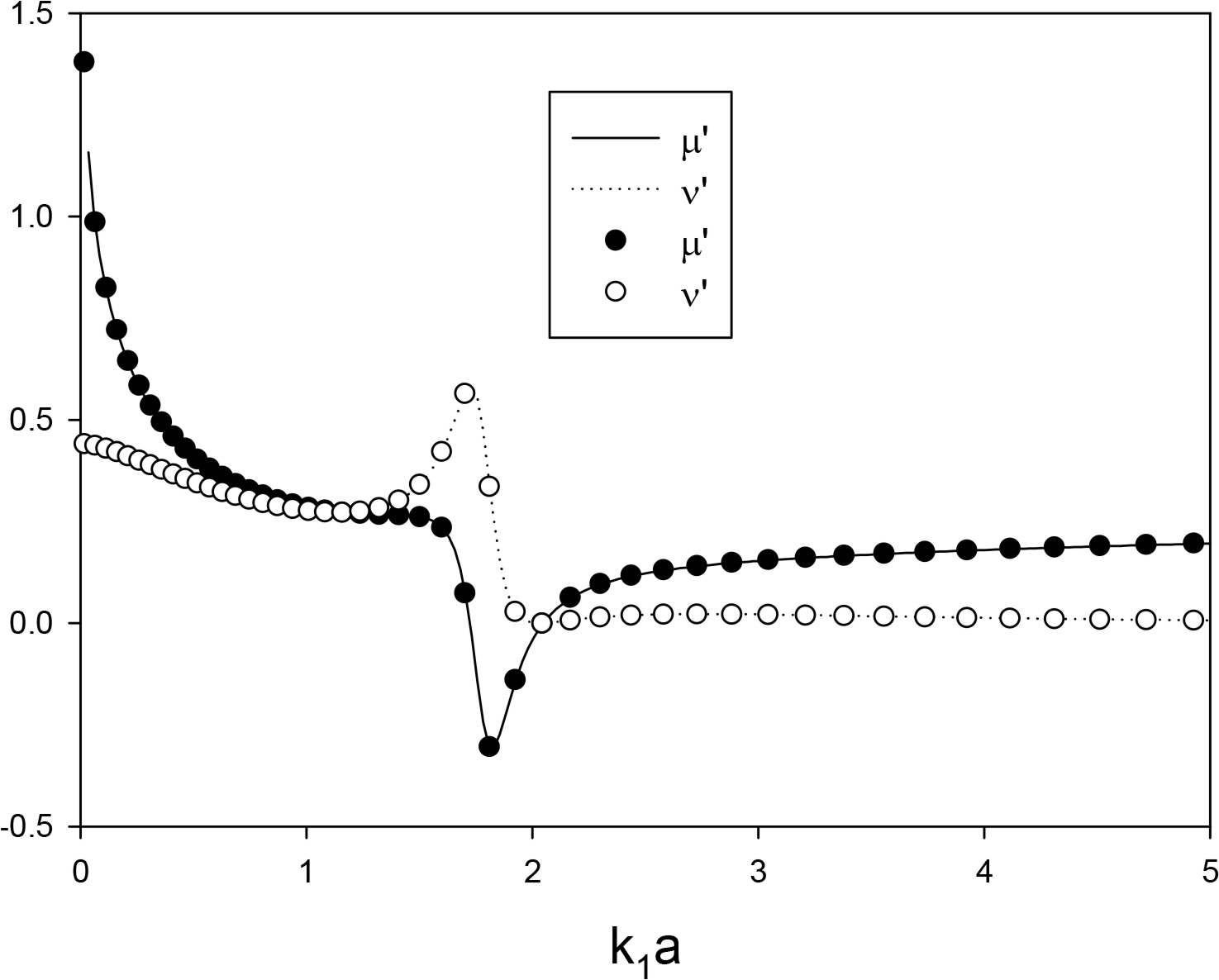
Comparison of non-dimensional added mass and radiation damping coefficients with Chau and Yeung’s results(●, ○) (h/a = 1.0, d/a = 0.25, b/a = 0.5)
Fig. 3 shows the non-dimensional wave exciting forces with respect to the changes in the draft (d = 6, 8, and 10 m). Here, the x-axis represents the frequency (ω) of the incident wave. The outer radius (a) and inner radius (b) of a floating OWC are 6 m and 4 m, respectively, and the water depth is 30 m. The drag coefficient (Cd) due to viscosity is 0.7. A peak value is observed at a specific frequency within the calculation region, and the peak frequency moves towards the low-frequency region as the OWC’s draft becomes deeper. The presence of these peak values can be explained based on the resonance. Two different types of natural frequency are present in a hollow cylindrical OWC. The first type is the natural frequency of a floating body’s heave motion. The natural frequency of heave motion varies according to the draft (d) of a floating OWC, where the natural frequency

Non-dimensional wave exciting forces as a function of draft d with a = 6 m, b = 4 m, h = 30 m
Fig. 4 shows the non-dimensional added mass (a33/m) and radiation damping coefficient (b33/mω) due to the heaving motion of a floating OWC under the same calculation conditions as those used for Fig 3. The radiation damping coefficient has a peak value when the added mass changes significantly, from a positive to a negative value, at the resonance frequency at the piston mode. This unique phenomenon occurs when a fluid region inducing resonance is present inside an object in motion. This phenomenon is observed in the present model since the fluid region inducing resonance exists within the hollow OWC in heave motion. The added mass and radiation damping coefficient having unique characteristics influence the motion response of a floating OWC device. Only the resonance at the piston mode is displayed since the internal fluid region is smaller than the wavelength of incident wave; however, not only piston mode, but also sloshing mode resonance needs to be considered if the internal fluid region is not smaller than the wavelength of incident wave (Molin, 2001).
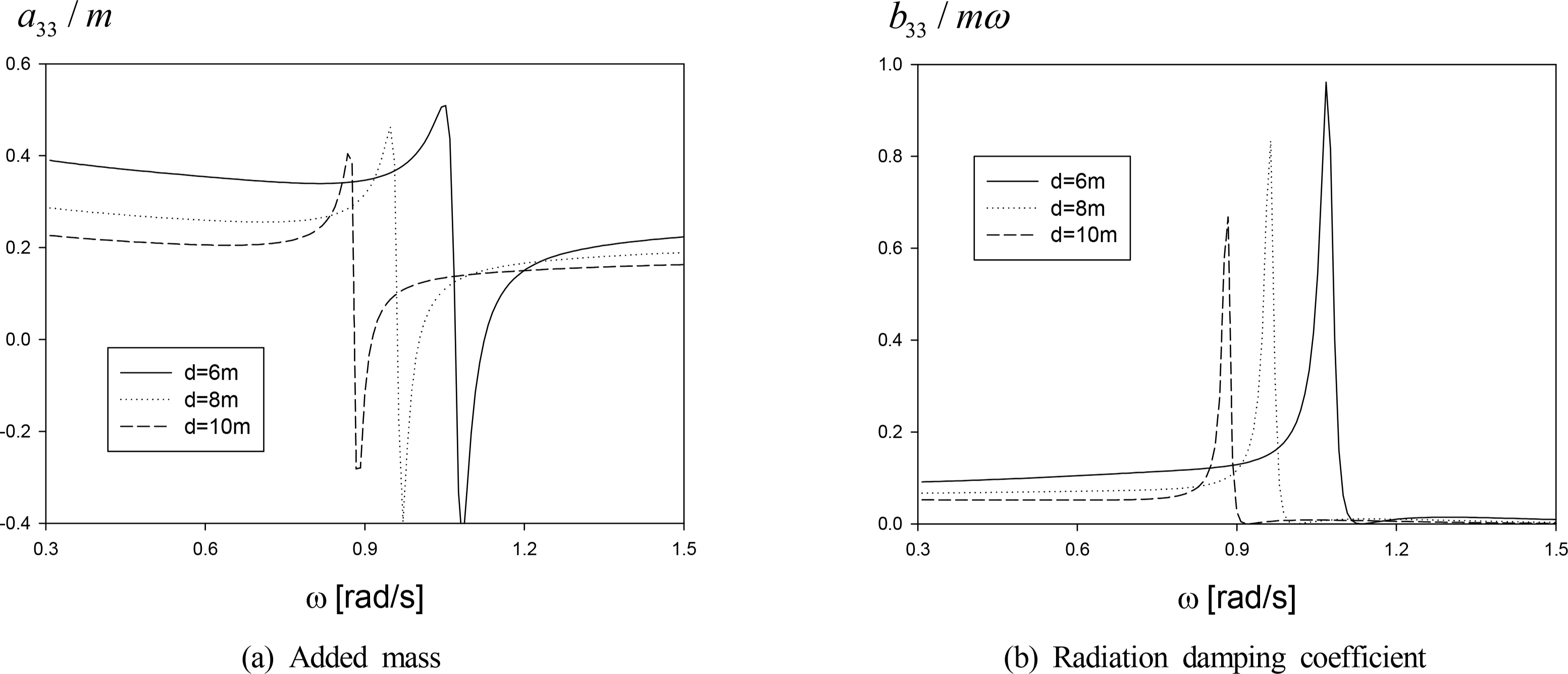
Non-dimensional hydrodynamic coefficients (a) added mass (b) radiation damping coefficient as a function of draft d with a = 6 m, b = 4 m, h = 30 m
Fig. 5 shows the flow rate inside the air chamber due to the incident wave and oscillating pressure in the chamber. First, the flow rate (q1 ) due to an incident wave when an OWC is fixed has a peak value at the natural frequency of piston mode, similar to a wave exciting force. Meanwhile, the flow rate (q3) by oscillating pressure in the air chamber has real part (B) and imaginary (C) parts. The curve shapes are similar to those of the added mass and radiation damping coefficient shown in Fig. 4. As the draft decreases, the peak values of B and C also decrease, while the resonance width increases.
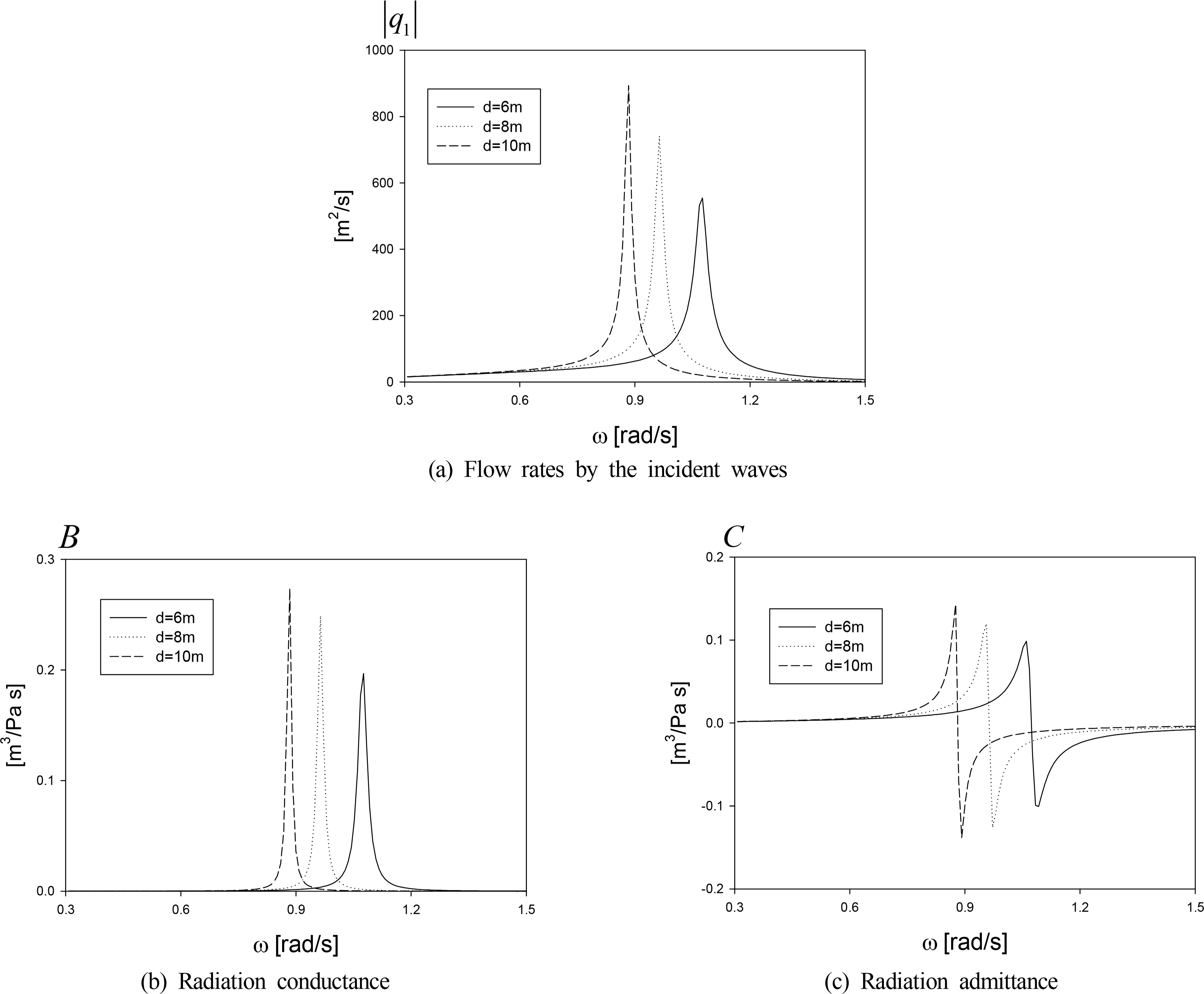
Induced flow rates due to the incident waves (a) and oscillating pressure (b), (c) as a function of draft d with a = 6 m, b = 4 m, h = 30 m
Fig. 6 shows the optimal turbine constant that results in maximum power as a function of frequency using Eq. (40). The optimal turbine constant has peak values at specific frequencies. Notably, the peak values of a turbine constant occur at the natural frequency of heave motion. Fig. 6(b) shows the response amplitude operator (RAO) of heave motion of a floating OWC when the optimal turbine constant is applied. The RAO curve of heave motion has two peaks, at the natural frequency of heave motion and at the piston mode natural frequency of the internal fluid. A relatively larger heave motion occurs at the natural frequency of the internal fluid. Fig. 6(c) shows the oscillating pressure inside the air chamber with respect to the frequency of an incident wave when the optimal turbine constant is applied. As predicted, the oscillating pressure has a peak value at the internal fluid resonance frequency, and no significant variation is observed at the natural frequency of heave motion. The extracted power shown in Fig. 6(d) is determined by the turbine constant and the oscillating pressure in the air chamber, as shown in Eq. (38). The frequencies that produce the maximum values of oscillating pressure and turbine constant are different; therefore, two peak values are also observed in the extracted power curve, similar to the heave RAO curve. Fig. 6(e) shows the capture width, determined by dividing the extracted power by the power of incident wave per unit width. As expected, two peaks are present, where the peak value is relatively larger at the internal fluid resonance frequency, similar to the heave RAO and extracted power curves. Moreover, with the increase in the draft of a floating OWC, the peak value at the internal fluid resonance frequency increases while the resonance width decreases; this is because the energy inside the internal fluid region cannot be escaped to the outside. Therefore, the draft of a floating OWC should be designed appropriately for maximizing energy absorption by identifying the wave characteristics of the installation site in advance.
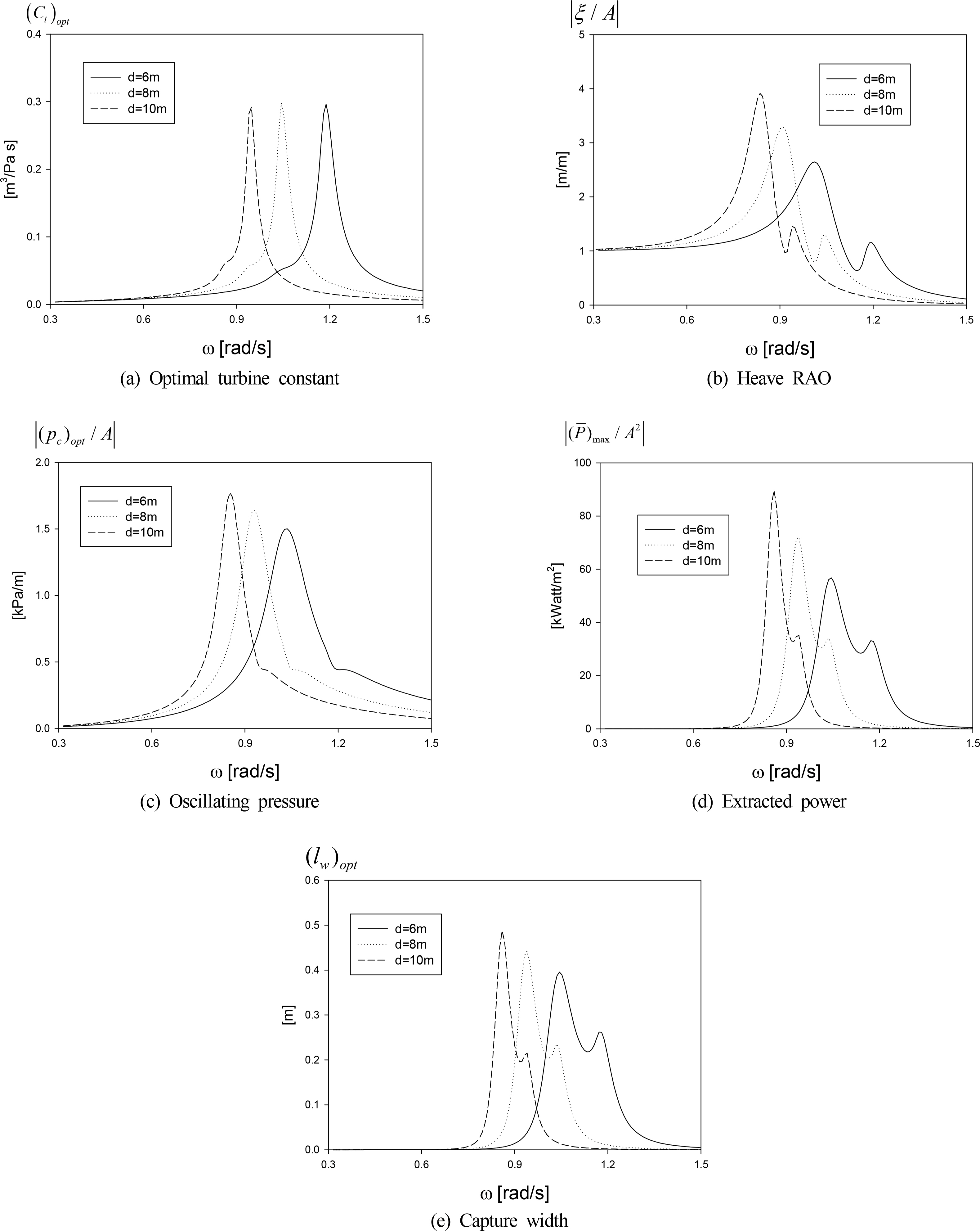
Optimal turbine constant and corresponding heave RAO, oscillating pressure, extracted power, and capture width as a function of draft d with a = 6 m, b = 4 m, h = 30 m, H = 5 m
Fig. 7 shows the heave RAO and capture width of a floating OWC with respect to the inner radius (b) of 3 m, 4 m, and 5 m, which is another important design parameter. The draft (d) and outer radius (a) of a floating OWC are fixed at 8 m and 6 m, respectively. The drag coefficient of a floating OWC is 0.7, and the optimal turbine coefficient is used. The heave natural frequency of a floating OWC within the calculated frequency region is 1.03 rad/s, 1.05 rad/s, and 1.07 rad/s as the inner radius increases; meanwhile, the resonance frequency of internal fluid in the piston mode is 0.98 rad/s, 0.95 rad/s, and 0.92 rad/s, thus being unaffected greatly by the inner radius of a floating OWC. However, the peak value of heave motion amplitude at the internal fluid resonance increases as the inner radius increases. In the maximum capture width curve obtained by applying optimal turbine constant, the capture width has one peak at the internal fluid resonance frequency when the inner radius is the largest at 5 m; the peak value decreases when the inner radius is the smallest at 3 m, and it increases again at the heave natural frequency, thus yielding two peak values. Consequently, the peak value decreases with the decrease of inner radius, but the frequency range for wave energy extraction increases. Similar to the draft, the inner radius of a floating OWC also needs to be designed appropriately for the wave characteristics of the installation site.
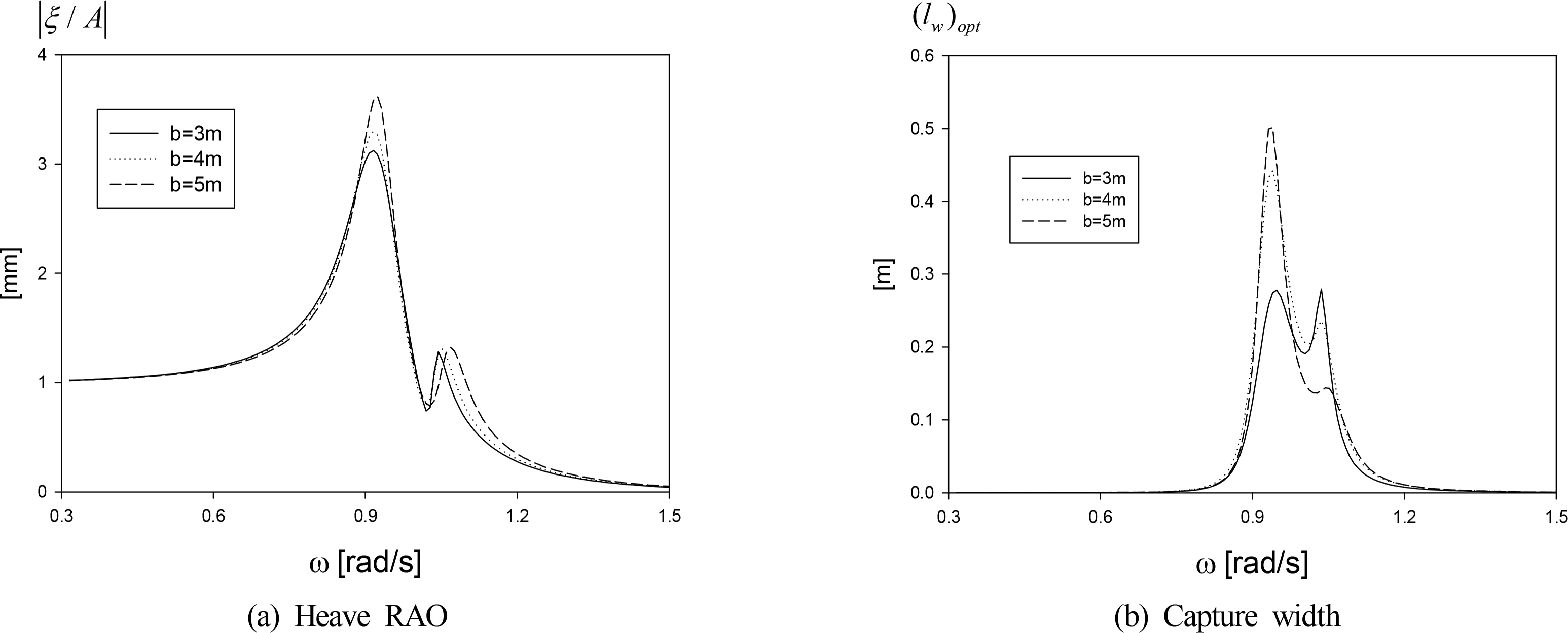
Heave RAO and capture width at optimal turbine condition as a function of radius b of inner fluid region with a = 6 m, b = 8 m, h = 30 m, H = 5 m
Fig. 8 shows a comparison of the coupled results between the oscillating pressure and the heave motion of a floating OWC with the uncoupled results obtained using Eq. (41). The heave RAO illustrated in Fig. 8(a) shows that the coupled heave RAO has a decreased peak value at the heave resonance frequency due to the influence of oscillating pressure inside the air chamber. The oscillating pressure inside the air chamber illustrated in Fig. 8(b) shows that the results of oscillating pressure uncoupled with a floating OWC are identical to the results of the fixed type of an OWC. Thus, when the oscillating chamber pressure and heave motion of a floating OWC are coupled, the oscillating pressure is closer to zero due to a small relative heave motion as a floating OWC moves along with the incident long waves; subsequently, a peak value is observed at the internal fluid resonance frequency due to the large displacement of the internal fluid. As predicted from Fig. 8, the power generation of a floating OWC is less efficient than that of a fixed OWC in long waves. Therefore, it is recommended to design the system such that the heave motion of the OWC is minimized. To this end, a damping plate can be installed at the bottom of a floating OWC, or a tension-leg mooring system can be introduced to minimize the heave motion of the OWC. Furthermore, a latching control technique, which is often adopted in a movable-type WEC, can be introduced to a floating OWC to maximize the extraction efficiency.

Comparison of heave RAO and oscillating air pressure between coupled and uncoupled condition at optimal turbine condition with a = 6 m, b = 4 m, d = 8 m, h = 30 m, H = 5 m
4. Conclusions
The following conclusions have been drawn from investigation of the heave RAO, oscillating air pressure, extracted power, and capture width of a floating hollow cylindrical OWC device with respect to changes in draft and radius of an OWC.
The oscillating chamber pressure, which significantly affects the extracted power of a floating OWC device, is considerably influenced by the heave motion of an OWC. Therefore, an equation of motion in which the heave motion of an OWC and oscillating air pressure in the chamber are coupled needs to be solved to accurately evaluate the performance of a floating OWC device. In the present study, a nonlinear viscous drag is considered through an equivalent linearization technique.
When an enclosed fluid region is present inside an OWC, the resonance of internal fluid is generated, and a corresponding double peaks are observed, unlike the motion characteristics of a general floating body exhibiting a single resonance. The heave motion response at the internal fluid resonance frequency is relatively larger than that at the heave natural frequency. The added mass at the internal fluid resonance frequency has a negative value, the corresponding radiation damping coefficient has a peak value. Furthermore, the flow rate of internal fluid due to oscillating pressure in the chamber, called radiation admittance and radiation conductance, shows a similar tendency as added mass and radiation damping coefficient.
The changes in draft and diameter of a floating OWC affect the two different resonance frequencies existing in the hollow cylindrical OWC model. The corresponding peak values and resonance width are changed too with the draft and radius. Therefore, the wave characteristics of the installation site need to be examined in advance to appropriately design the draft and radius for yielding the maximum extraction power.
For a floating OWC device that is identical in shape to a fixed OWC, the power generation efficiency in the long waves is less than that of the fixed OWC. Therefore, the damping plate can be installed at the bottom of a floating OWC, or a tension-leg mooring system can be introduced to minimize the heave motion of an OWC. Moreover, a latching control technique can be introduced to a floating OWC to maximize extraction efficiency.
Notes
This research was funded by the Korea Institute of Energy Technology Evaluation and Planning (KETEP) and the Ministry of Trade, Industry & Energy (MOTIE) of the Republic of Korea (Grant No. 20163010071690).