1. Introduction
A two-dimensional (2D) wave tank generates water waves and has been used as an experimental device to perform various hydrodynamic analyses; for example, it is used to investigate the wave-wave and wave-body interactions. However, such a wave tank generates unnecessary reflected waves at the end wall of the tank owing to its limited physical size. Therefore, it is crucial to install an efficient wave absorber to continuously measure the waves generated by the wave maker and maximize the observation range.
Jung and Cho (1999) confirmed that when used as a wave absorber, a flat punching plate performs better than conventional wave absorbers. Cho and Hong (2004) confirmed that the porosity of the punching plate should be 10% and its sloping angle should be within 10°–20° to achieve maximum wave absorption performance when an inclined punching plate is used as a wave absorber.
In this paper, we proposed a combined wave absorber by combining a flat punching plate and a sloping punching plate to minimize the reflected waves in a 2D mini wave tank. Additionally, an experimental study was conducted to evaluate the performance of the proposed punching plate. We separated the incident waves and the reflected waves using the least square method (Mansard and Funke, 1980) to determine the performance of the wave absorber. This method is to minimize the sum of squares of error between the waveform obtained through an equation and the measured waveform. This method usually uses three wave gauges to measure wave elevations. However, in this study, we measured the incident waves and the separated reflected waves by installing four wave gauges for better accuracy.
The sections of the measured waves to be analyzed should be selected appropriately to achieve an accurate separation between the incident waves and reflected waves. The reflected waves were measured in the steady-state section until the incident waves were reflected from the wave absorber at the end of the tank and then reflected again from the wave maker and reached the same wave gauge. The measured waves were separated into incident waves and reflected waves. In this study, we proposed a novel combined punching plate wave absorber that combined a flat punching plate and sloping punching plate. Additionally, we determined the wave absorption performance, and porosity and slope conditions required for the optimal wave absorption performance of the proposed punching plate.
2. Separation of Reflected Waves
In this study, we installed four wave gauges at appropriate intervals in the wave tank to separate the incident and reflected waves. We used the reflected wave separation method proposed by Goda and Suzuki (1977) using the measured wave height data, referring to Suh et al. (2001) and Park et al. (1992). When the frequency of the incident wave is ω, the incident wave elevation (ζI) and the reflected wave elevation (ζR) can be expressed using Eqs. (1) and (2), respectively.
Here, HI and HR denote the incident wave height and reflected wave height, respectively, ∊I and ∊R denote the phase difference of the incident wave and reflected wave, respectively, and k denotes the wave number. The time series of waves measured at a particular position by the superposition method of the incident and reflected waves can be represented by Eq. (3):
where en(t) refers to the measurement error for the non-linear interference or noise of waves included in the wave height data measured by the nth measurement position (nth wave gauge), and ln indicates the distance from the reference point to the nth measurement position.
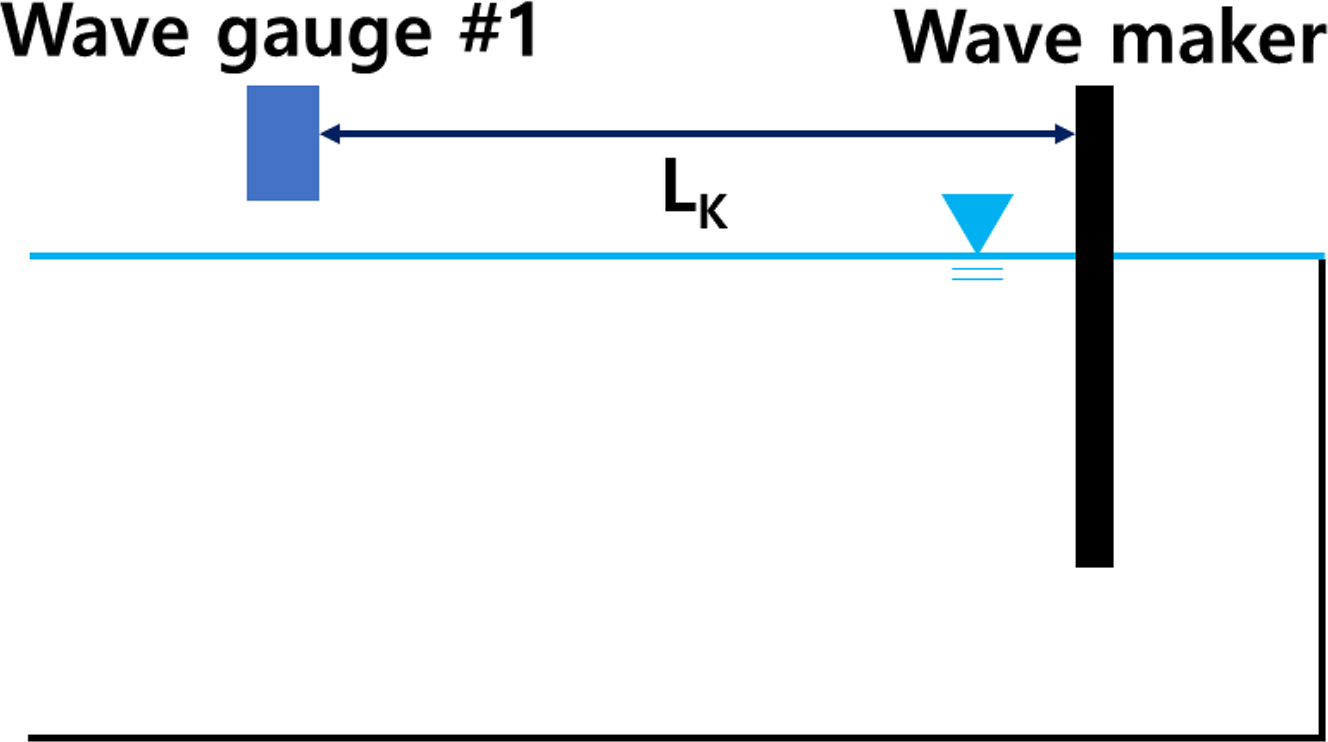
The reference point was set at a distance of 2 m (Lk) from the wave maker to the first wave gauge (Fig. 1). If Eq. (3) was organized using a trigonometric theorem, it can be represented as Eq. (4), and the equation for X is provided in the appendix.
Meanwhile, the measurement data error for separating the incident and reflected waves can be expressed as the sum of the squares of errors included in the measurement data, as shown in Eq. (5).
Here, N represents the number of wave gauges, and Tm represents the measured time. With error (E), which is the sum of measurement errors, if the differential value for Xi, a coefficient related to the wave heights and phases of incident and reflected waves, becomes 0, the error for each coefficient can be minimized. If four X1–X4 were calculated using this method, the height and phase of the incident and reflected waves can be obtained. Eq. (7), which is a linear algebraic matrix equation, can be composed using Eq. (6), which can minimize the minimum/maximum of the error (E):
where Cij expresses the right side of Eq. (4) as a trigonometric function, and Fj denotes the wave measured at each wave gauge. This equation is provided in detail in the appendix. By calculating Eq. (7), the coefficient Xi can be obtained. Finally, Eqs. (8)–(11) were applied to calculate the wave height and phase of the incident and reflected waves.
3. Experimental Equipment and Description
3.1 Two-dimensional Wave Tank
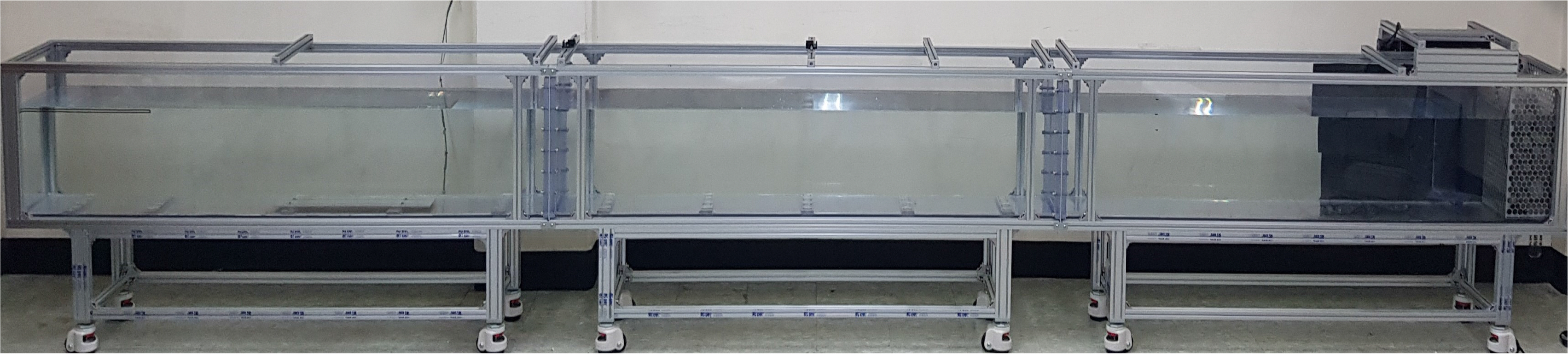
In this experimental study, we used the 2D mini wave tank in Inha University. The wave tank was 0.3 m wide, 6 m long, and 0.5 m deep. As the bottom and sides of the tank were made of transparent acrylic material, the waves could be observed from any direction (Fig. 2). The piston-type wave maker was installed in this tank (not an active-damping wave maker). The experiment was conducted by excluding the effect of reflected waves by measuring the wave before the generated wave was re-reflected by the wave maker. A 0.1 s period interval was used in a 0.8–1.2 s range of the incident wave period, and the wavelength was 0.98–1.86 m.
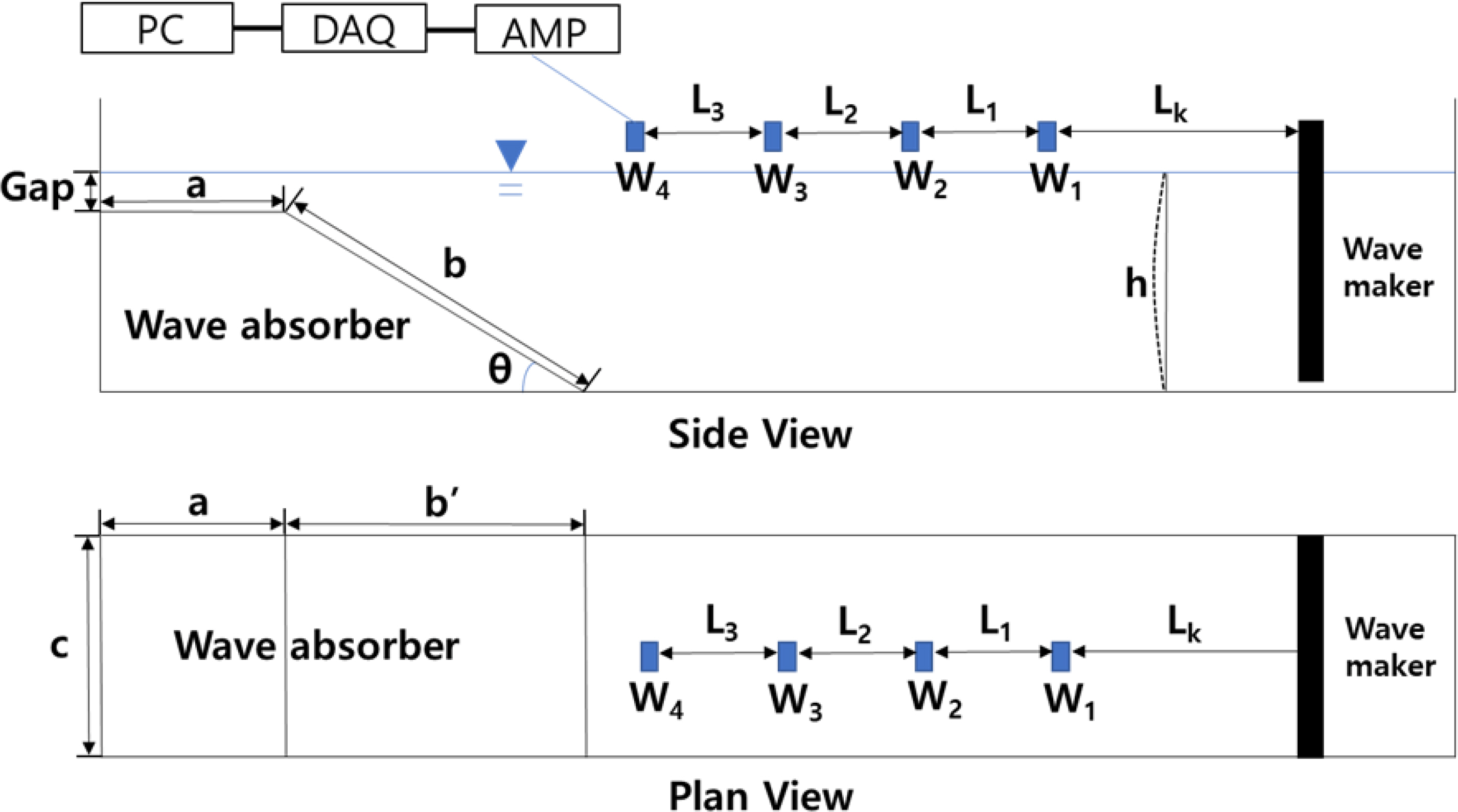
Uniform regular waves were generated at a wave height of 0.5 cm, 1 cm, 2 cm, and 3 cm, respectively. Wave data were collected 20 times per second using wave gauges. Fig. 3 shows the side view and plan view of the overall schematics of the 2D mini wave tank with the punching plates installed. Table 1 shows the experimental conditions for wave length for each wave period.
In the side view shown in Fig. 3, the water depth (h) was 0.35 m, and the flat punching plate (Position A) was installed such that it was submerged 0.01 m (Gap) from the free surface. The ultrasonic wave gauges were named as wave gauge #1 (W1), #2 (W2), #3 (W3), and #4 (W4), respectively. The spacing between each wave gauge was all set uniformly to 0.3 m, and the spacing (Lk) between the wave maker and wave gauge #1 (W1) was set to be 2 m considering the evanescent wave mode. The length (a) of the flat punching plate was 0.5 m, and in Case 1, the length (b) and angle (θ) of the sloping punching plate were 1 m and 18.6°, respectively. The experiment was conducted on three conditions for the length (b) and angle (θ) of the sloping punching plate. In the plan view of Fig. 3, the width of the wave tank (c) was 0.3 m, and in Case 1, the projected length (b′) of the sloping punching plate was 0.94 m. The signals measured by the ultrasonic wave gauges were amplified using an amplifier (AMP) and sent to a data acquisition device (DAQ). Then, the data were stored and analyzed on a computer.
3.2 Punching Plate Wave Absorber
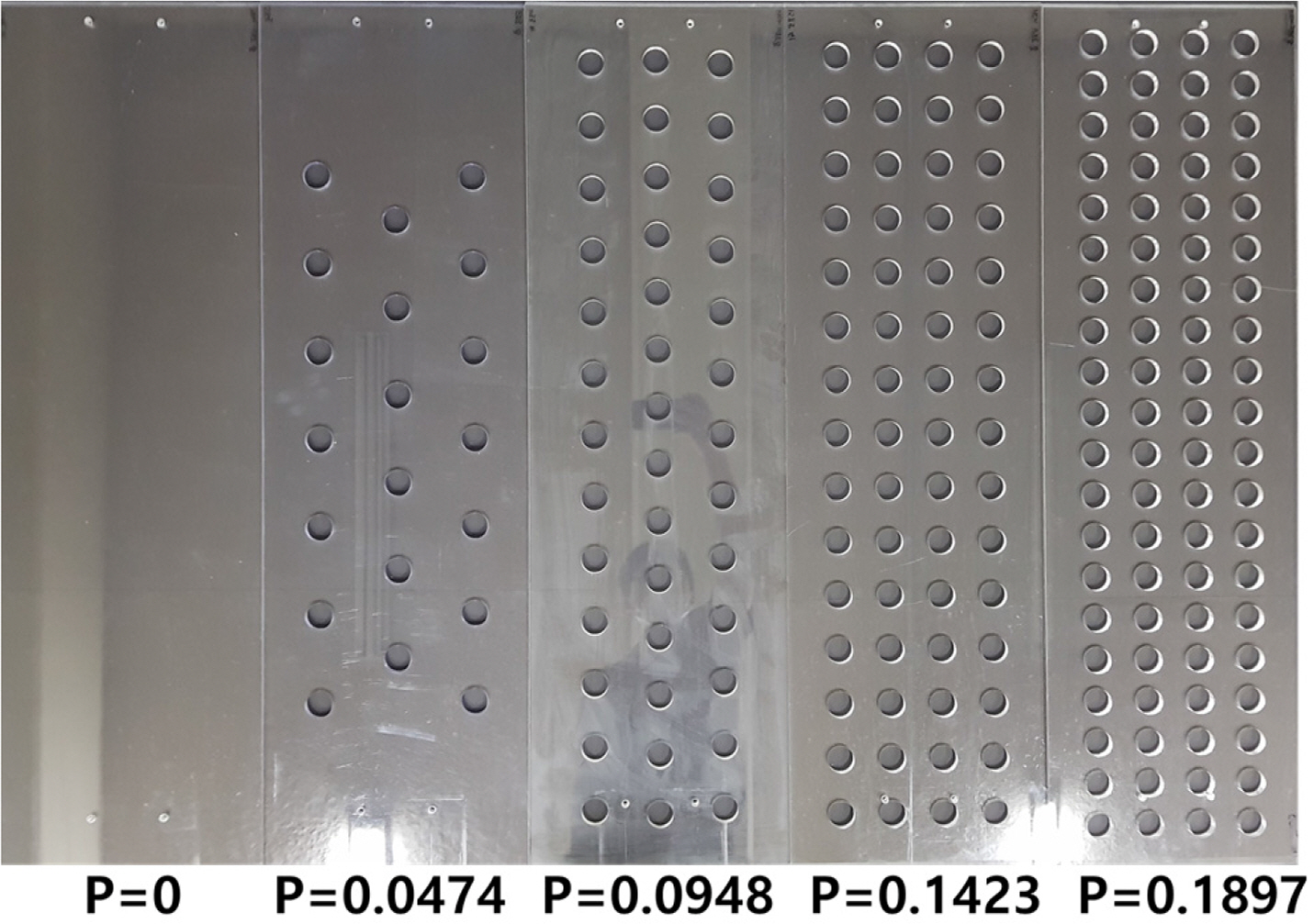
The wave absorber was installed at the end of the mini wave tank by combining a flat punching plate and a sloping punching plate. Fig. 4 shows a schematic diagram of the punching plates used in the wave absorber. Holes of the same diameter (D) and spacing (B) were drilled onto the plates to maximize the wave absorption effect. D and B of all punching plates were identical, and the number of pores (circles) varied depending on the porosity of the punching plate. The punching plates were fabricated using an acrylic material having a thickness of 10 mm.
Fig. 5 shows the punching plate corresponding to the flat plate of the combined wave absorber. The dimension of the flat punching plate was 500 × 298 mm. In this study, porosity (P) is given as a ratio of the perforated area to the total area of the plate.
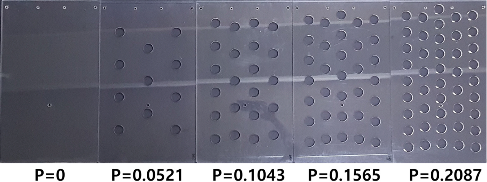
Fig. 6 shows the sloping punching plate with various porosities having the dimension of 1000 × 298 mm, and Table 2 shows the dimension of the flat and sloping punching plates. Each punching plate was fabricated with a porosity of approximately 0%–20% (Table 3). In this study, we conducted the experiment by changing the installation angle and length (Table 2) at a porosity of 0% (P = 0) for the sloping punching plate (b).
3.3 Ultrasonic Wave Height Gauge
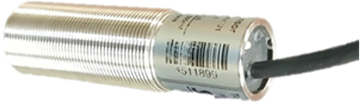
In this experiment, we used Senix TSPC-30S2 ultrasonic wave gauges, whose picture and specifications are shown in Fig. 7 and Table 4. Each ultrasonic wave gauge was installed in the vertical direction on the free surface. This device measures the height of the free surface by measuring the time that the ultrasonic wave generated by the wave gauge is reflected at the free surface. The wave gauges have a built-in temperature compensation circuit because the propagation speed of ultrasonic waves is slower in air than in water. Furthermore, the change in speed of ultrasonic waves due to temperature change cannot be ignored.
4. Results and Analysis of Reflected Wave Separation Experiment
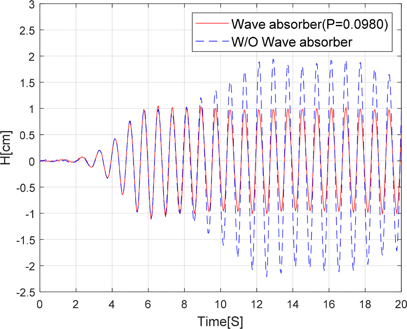
Fig. 8 shows the time-series results comparing the change in the free surface when the wave absorber was installed and when it was not installed. Here, a combined punching plate with an average porosity of 10% (P = 0.0980), which combined a flat punching plate with a porosity of 10% (P = 0.1043) and a sloping punching plate with a porosity of 10% (P = 0.0948), was installed as the wave absorber, and the time series data measured by the third wave gauge were compared. The wave period of the incident wave was 1.2 s and the wave height was 2 cm. The free surface elevation measured between approximately 6 and 9 s after the generation of an incident wave confirmed that the steady-state was shown irrespective of whether the wave absorber was installed or not. Therefore, it was determined that the reflected waves did not enter the measurement section of the mini wave tank completely. However, after approximately 9 s, when the incident wave was reflected from the end wall of the tank entered the measurement section after being re-reflected by the wave maker plate, the free surface elevation increased by approximately 100% in the case of no wave absorber. On the other hand, when the combined punching plate was installed, crest and trough values of the free surface elevations were well maintained in a section of 2 cm, i.e., the incident wave height. This meant that the incident wave was no longer reflected from the wave absorber and most of the energy was dissipated, thereby showing the wave absorption performance of the punching plate.
Based on these results, we compared the wave absorption performance of the flat punching plate (Fig. 9) and combined punching plate (Fig. 10) according to the porosity of the punching plate in terms of the reflection coefficient. Here, R denotes the reflection coefficient, k denotes the wave number, and h denotes the water depth. The incident waves were generated at 0.1 s intervals with wave height of 2 cm and wave period of 0.8–1.2 s. The experiment was performed using punching plates with five porosities (P = 0–0.2087).
Fig. 9 shows that the reflection coefficient is similar for when a flat punching plate with 0% porosity (P = 0) is installed and when no punching plate is installed. Furthermore, the reflection coefficient generally increases from the short-wave to the long-wave. This shows that although the flat punching plate (0% porosity, P = 0) has been installed, the incident waves are not attenuated by the flat plate alone. However, when the flat plate was porous, considerably superior wave absorption performance was observed, and particularly, good wave absorption performance was confirmed for long-waves. Furthermore, it was confirmed that the deviation of the reflection coefficient according to the wavelength was not very large. When the porosity of the flat punching plate was approximately 5% (P = 0.0521), the reflection coefficient was less than or equal to 0.3, but when the porosity was approximately 10% (P = 0.1043), the reflection coefficient was less than or equal to 0.1, i.e., it demonstrated the best wave absorption performance. However, for a large porosity of 20% (P = 0.2087), the reflection coefficient increased rather slightly in the long-wave region (kh = 1.2). In brief, when the porosity was 10% (P = 0.1043) on the flat punching plate, the mean reflection coefficient was approximately 0.07, i.e., the best reflection coefficient.
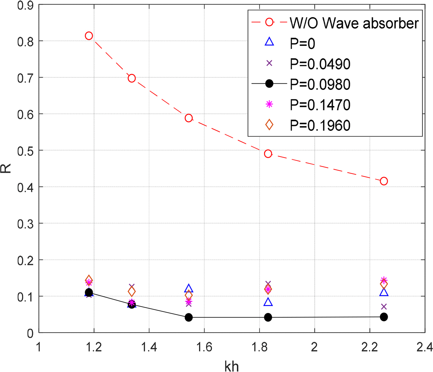
Fig. 10 compares the reflection coefficient of different incident wavelengths for the combined punching plate. The porosity was identical between the flat plate and sloping plate in each condition. The combined punching plate was inclined at 18.6°. Compared with the flat punching plate case (Fig. 9), a significantly better wave absorption performance was observed with a reflection coefficient of approximately 0.1 for 0% porosity condition (P = 0). Based on this, it was determined that the installation of the sloping plate results in a shoaling effect of incident waves, and the wave energy decreases due to the interaction with the flat plate. Similar to the case of the flat punching plate, it was confirmed that the best wave absorption performance (a low reflection coefficient) was observed for a porosity of 10% (P = 0.0980) under the combined punching plate condition. This shows that the optimal porosity was generally approximately 10% irrespective of the incident wavelength. Cho (2013) also obtained similar results. Therefore, it can be expected that the energy loss rate of the incident wave is the largest when the porosity of the punching plate is 10%. As reported by Ko and Cho (2018), the load on the punching plates is expected to decrease if the porosity increases. This is because the pressure difference between the punching plates decreases. Furthermore, for the combined punching plate, the effect of installing the sloping punching plate is greater than the wave absorption performance produced by the porosity change.
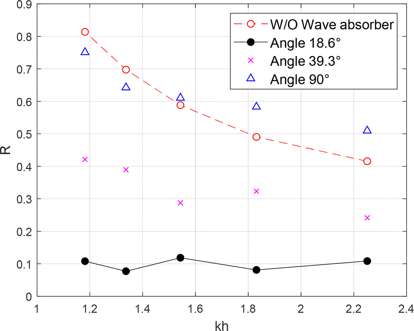
Fig. 11 shows the comparison of wave absorption performance between various slope angles of the sloping plate of a combined wave absorber with 0% porosity (P = 0). When the installation angle of the sloping plate was 90°, the result was very similar to that of the case where there was no wave absorber. Moreover, the reflection coefficient increased in the short-wave region. When the angle of the sloping plate was 39.3°, the reflection coefficient was approximately 0.3 to 0.4, showing a certain degree of wave absorption performance. However, when the slope angle was 18.6°, the best wave absorption performance was recorded. Therefore, for the given conditions of this experiment (incident wave period: 0.8–1.2 s, water depth: 0.35 m), it was appropriate to maintain the angle of the sloping plate at approximately 18.6° to achieve effective wave absorption performance. Ko and Cho (2018) reported that the optimal angle for the sloping punching plate ranged from 10°–20°. Therefore, we determined the angle that can produce an appropriate shoaling effect when an incident wave enters the punching plate area. In this experiment, no breaking wave occurred on the sloping punching plate. However, some breaking waves occurred on the flat punching plate because the waves that entered the flat plate were reflected at the end wall of the wave tank, resulting in superposed waves.
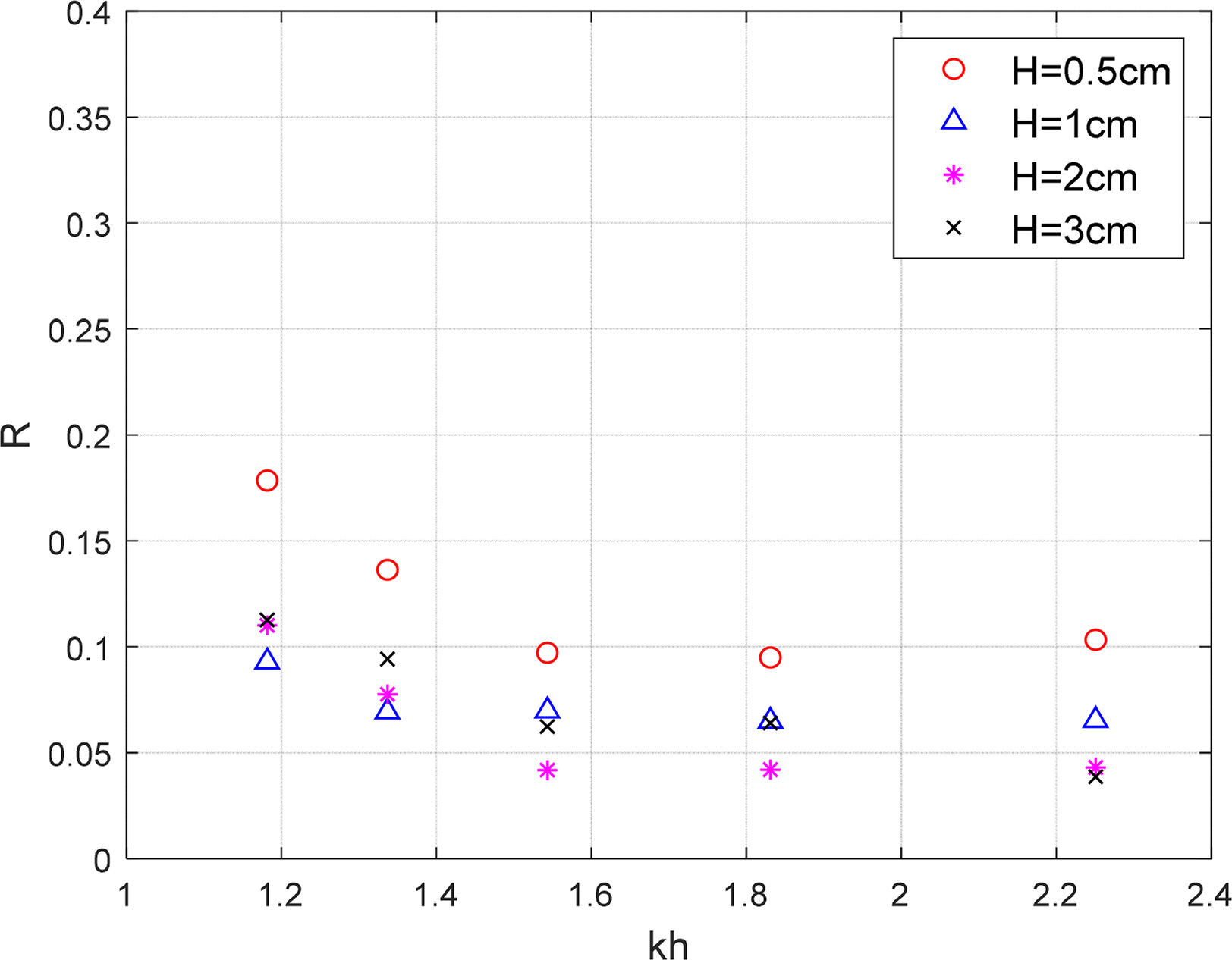
Fig. 12 shows the comparison of the change in wave absorption performance of the combined punching plate at different incident wave heights. The sloping plate was inclined at 18.6° and the porosity of the combined punching plate was 10% (P = 0.098). When the incident wave height was 0.5 cm, the reflection coefficient increased in all wave frequencies. This is because the installation depth of the flat punching plate was 1 cm below the free surface, so when the incident wave height is small, the wave absorption effect of the flat punching plate cannot be expected. When the wave height was greater than 1 cm, the reflection coefficient was less than or equal to 0.1, which showed significantly effective wave absorption performance. Generally, similar wave absorption performance was shown irrespective of the wave height. Furthermore, the reflection coefficient generally increases as the incident wavelength increases (as khdecreases). This result is similar to the conclusion of a study conducted by Yuan et al. (2013), which states that the reflection rate increases as the wave frequency increases on a sloping punching plate.
Overall, combined punching plates have better wave absorption performance than separated punching plates. As the flat plate is combined with the sloping plate, the incident water particles with a circular or elliptical trajectory produce a shoaling effect with the sloping plate, thereby increasing the wave height. Here, as the water particles near the free surface enter more above the flat plate, the wave energy is attenuated at the pores of the flat plate, and additional energy is attenuated as the waves reflected from the end wall of the wave tank are superposed, thereby breaking the waves. The energy of wave particles below the free surface is consumed at the pores of the sloping plate. Therefore, it is understood that a significant amount of wave energy is attenuated on the flat punching plate, and additional wave energy is consumed by the sloping punching plate.
5. Conclusion
In this study, we proposed a combined wave absorber by combining a flat punching plate and a sloping punching plate. Additionally, the wave absorption performance of the proposed wave absorber was comparatively analyzed according to the porosity of the punching plates, existence/absence of the sloping punching plate, installation angle of the sloping plate, and incident wave height. The punching plate wave absorber was installed in a 2D mini wave tank having a length of 6 m to conduct the experiments. We installed four wave gauges and separated the reflected waves by using a least square method to analyze the reflection coefficient to determine the wave absorption performance.
For installing the punching plate wave absorber, it was confirmed via time series comparisons that the reflected waves were suppressed and incident waves of the steady-state were measured for a long time. When the flat punching plate was installed, the wave absorption performance was excellent at a porosity of 10% (P = 0.1043).
When the combined punching plate was installed with a porosity of 10% (P = 0.0980) with the punching plate having an installation angle of 18.6°, the reflection coefficient was reduced by up to 95%, thereby showing the most effective wave absorption performance. This means that the combination of a flat punching plate and a sloping punching plate can effectively attenuate the incident wave energy. When the incident wave height was greater than the installation depth of the flat punching plate, the difference in wave absorption performance due to the wave height change was not that large, and all cases showed excellent performance.
The installation angle of the sloping plate produces a shoaling effect when the incident wave enters the plate, thereby increasing the incident wave height. The wave absorption performance can be improved if more water particles enter above the flat punching plate. However, owing to the limitations of the experimental equipment and physical conditions, additional comparisons and a precise analysis of wave absorption performance are required for more segmented slope angles in the future.