Current Measurement and Velocity Spatial Distribution of Deep Ocean Engineering Basin
Article information
Abstract
To ensure the international competitiveness of the domestic offshore plant industry, a consensus has been formed regarding the requirement for large offshore basins for performing offshore plant performance verification. Accordingly, the Korea Research Institute of Ships & Ocean Engineering has built the world’s largest deep ocean engineering basin (DOEB). The purpose of this study is to evaluate the characteristics of velocity distribution under various conditions of the DOEB. An independent measuring jig is designed and manufactured to measure the current velocities of many locations within a short time. The measurement jig is a 15-m-high triangular-truss structure, and the measurement sensors can move 15 m vertically through an electric motor-wire device. The current speed is measured under various impeller revolutions per minute and locations of the DOEB using the jig. The spatial distribution characteristics of the current velocity in the DOEB and the performance of the current generator are analyzed. The maximum speed is 0.56 m/s in the center of the DOEB water surface, thereby confirming sufficient current velocity distribution uniformity for model testing.
1. Introduction
In the past around 2010, the offshore plant construction industry was extremely active, and the demand for model test basins for verifying offshore plant performance increased significantly. However, almost all demand was concentrated in the large European basins; as such, tests could only be performed during available slots. Accordingly, a consensus was formed regarding the requirement for a large ocean engineering basin in Korea to increase its international competitiveness in the offshore plant industry and to verify the front-end engineering design and performance of offshore plants. Consequently, the world’s largest deep ocean engineering basin was constructed in Korea.
The deep ocean engineering basin is the world’s largest rectangular basin, with an operating area measuring 100 m (length) × 50 m (width). Equipped with a depth control device, it can simulate all depths in the range of 0 to 15 m. The pit in the middle of the basin is 12 m in diameter and 50 m deep based on the waterplane, thereby enabling the use of prototype models instead of truncated models for model tests of deep-sea risers and tension leg platforms, where the effect of water depth is important. The deep ocean engineering basin is equipped with a wave generating system, wind generator, and current generator to simulate the various environments of the ocean, rendering it an optimal facility for evaluating offshore plants. In this study, the characteristics of currents generated through a current generator, which is one of the environment simulation devices inside the deep ocean engineering basin, were measured and analyzed. The current generating system comprises five impellers and six layers, and it can generate the vertical velocity profile of a current based on requirements imposed.
Yang et al. (2000) measured and analyzed the current characteristics of existing rectangular offshore basins in Korea and derived a relationship correlating the rotational speed of the impeller and the average flow velocity. Oh and Lee (2018) enabled flow rate control by installing a circulation system inside a two-dimensional wave generating basin. However, the only publicly available data pertaining to the current generator of a large offshore basin capable of controlling the vertical velocity profile are those of the ocean engineering basin currently operated by the Maritime Research Institute of Netherlands (MARIN) (Buchner et al., 1999; Buchner et al., 2001; Buchner and de Wilde, 2008). The basin operated by the MARIN measures 46 m (length) × 36 m (width) × 10.3 m (depth) and is smaller than a deep ocean engineering basin; nonetheless, it is the most preferred commercial rectangular basin in the world. The MARIN’s basin comprises a weight to be fixed to the floor, a wire system, and a lightweight structure that is connected to the wire system and can move along the water depth, allowing the velocity at each depth to be measured.
In this study, the current velocity was measured under various test operating conditions of the deep ocean engineering basin current generator using a custom-developed current measurement jig. Subsequently, the performance of the current generator and the spatial distribution characteristics of the current velocity within the deep ocean engineering basin were analyzed. Based on the results of this study, an optimal current generator operation plan for the performance evaluation of the offshore plant will be derived.
2. Method for Measuring Current
2.1 Current Generator of Deep Ocean Engineering Basin
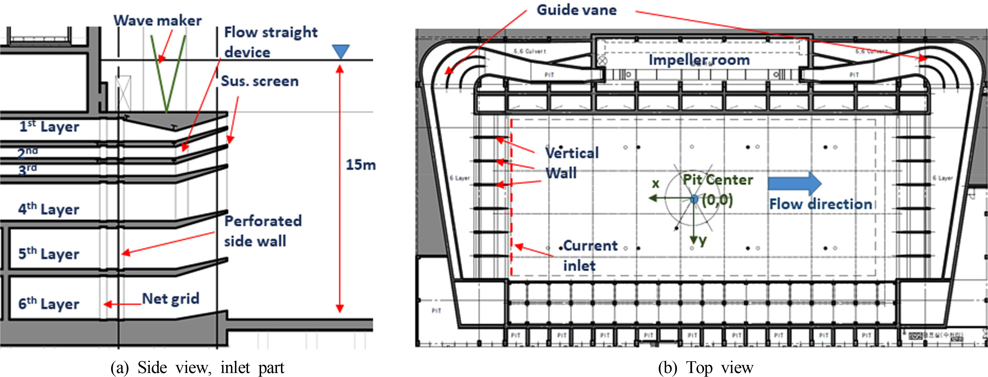
The main components of the deep ocean engineering basin current generator are shown in Fig. 1. Flow is generated from the five ducts, composed of pumps and motors, inside the impeller room. The basin comprises six layers of different depths. Because the wave maker is above these layers, the first layer is distant from the water surface. In the fifth and sixth layers, flow is generated by a single impeller. The rotational speed of the impeller in each of the ducts, which are separated by depth, can be controlled independently. However, in the fifth and sixth layers, the flow velocity is controlled only through the fifth impeller at the bottom. Subsequently, the flow passes through a guide vane and various rectifying devices in the mixing chamber, thereby yielding a uniform current. Similar rectifying devices are installed downstream, and as shown in Fig. 1(b), the flow circulates in the counterclockwise direction. To produce a uniform current, various rectifying devices (net grid, perforated side wall, distributing plate, screen, etc.) were designed for the inlet and outlet based on various computational fluid dynamics(CFD) analyses (Park et al., 2014; Haro et al., 2018).
2.2 Design of Jig for Current Velocity Measurement
Similar to a previous study by the MARIN, if the measuring device is fixed to the floor, then the operation of the current pump must be halted, the control device depth increased, and the weight-type fixing device on the floor shifted to change the horizontal position. This necessitates a significant amount of time for current measurement. In this study, a current measurement jig optimized for current measurement and the deep ocean engineering basin environment was designed and assembled.
To obtain the current velocity profile inside the deep ocean engineering basin, many areas must be measured when the current pump is being operated. Considering the length, width, and depth of the basin, it is essential to reduce the measurement time. Therefore, a measurement jig that requires a shorter measurement time is necessitated, and a structure that does not cause deformation, deflection, and vibration due to fluid flow (current) must be designed for a stable current velocity measurement.
To satisfy these conditions, the deep ocean engineering basin measurement jig was installed on the measuring frame of the towing tank to enable movement in the X–Y plane (forward/horizontal movement of the tank), and three current measurement sensors were attached on the measurement jig in equal intervals along the depth direction. If the jig is fixed only onto the measurement frame of the tank, the jig may shake; therefore, the bottom of the jig was reinforced by a rubber support such that it can be supported on the floor. Because the upper and lower ends were strongly fixed, vibration can be minimized. As confirmed during the actual operation, even when the jig was not fixed to the floor, the vibration of the jig or the measured value was not affected. The initial design features are shown in Fig. 2.
The basic shape of the current measurement jig was based on a vertical triangular-truss structure that allowed movement in all sections of the 15 m depth, and a linear motion guide for the Z-axis (depth direction) movement was placed vertically at the front of the current inlet such that the installation jig for the measurement sensor can move. The measurement sensor installation jig was driven by rotating the electric clutch type winch using an electric motor as well as driving it up and down both ways; meanwhile, the wire cable in the vertical direction was wound up and rotated. Stainless use steel, which can be used underwater, was used as the material for the wire cable, and it was designed to maintain a constant tension to maintain an accurate position. The motion of the sensor bracket was restrained in all directions except the vertical transfer direction.
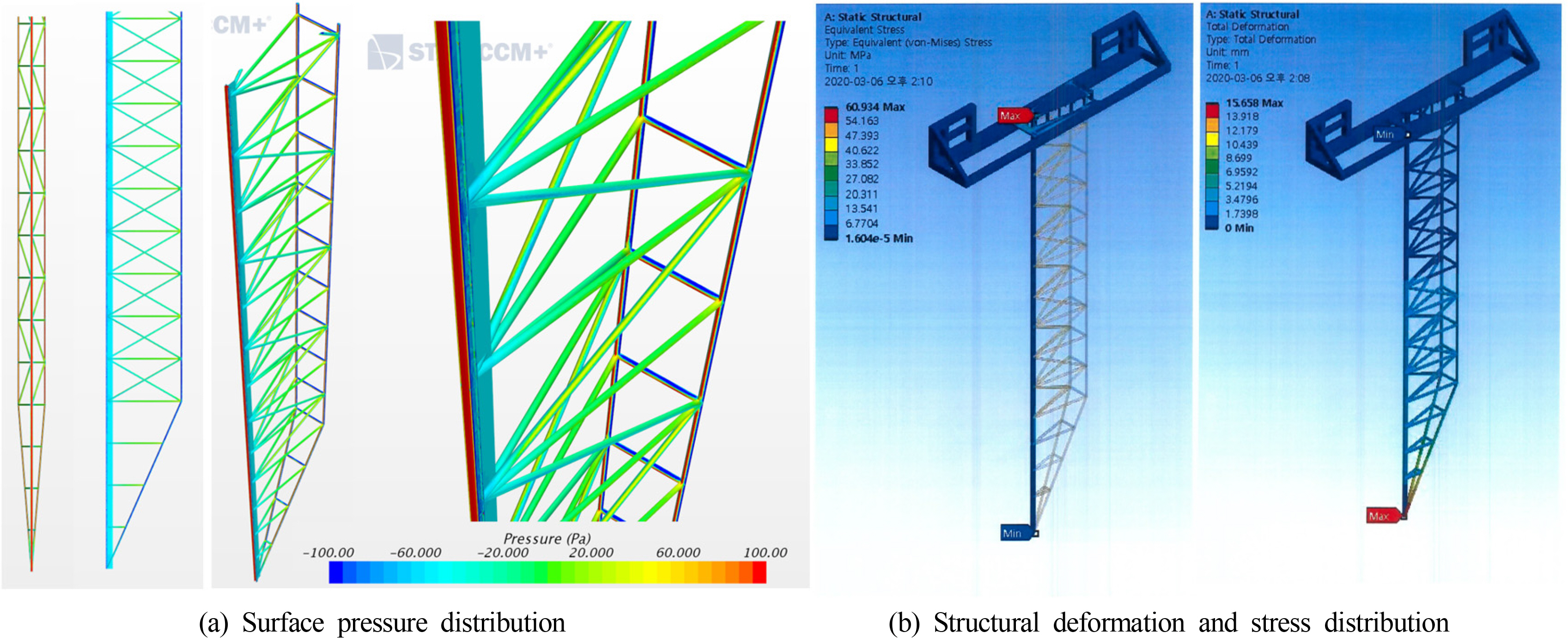
The basic shape was of a 15-m-long heavy structure, and a primary fluid load analysis was performed on the basic design using StarCCM+(Ver. 11.06) to determine the load value required for structural analysis (Fig. 3(a)). The fluid load analysis was performed using two flow velocities: 0.5 m/s, which is the design value for the deep ocean engineering basin current velocity; and 1 m/s, which is the extreme environmental condition. The current velocity decreased toward the lower part compared with the conditional velocity; however, a uniform flow was assumed for a conservative structural strength calculation. Using this value as the load condition, the primary structural analysis was performed using Ansys (2020 R2), and the structural characteristics, strength, and stress of the current measurement jig structure were analyzed. Based on the result of the structural analysis, a maximum stress of 60.934 MPa was confirmed at the uppermost assembly of the triangular-truss, and a maximum deflection of 15.66 mm at the bottom of the structure. The structural deformation and stress distribution are shown in Fig. 3(b). The maximum stress generated on the structural member was satisfactory. Similarly, the deflection, which was approximately 1/1000 the total height of the structure, was satisfactory. Therefore, the detailed design phase was proceeded in the study.
A detailed design was performed based on the basic design. For it to be operable in shallow water, it was designed such that it can be disassembled in the longitudinal direction. Subsequently, considering the efficiency in terms of manufacturing/assembly/installation, the vertical frame shape, measurement sensor jig size and shape, pipe diameter, and truss length were slightly modified. A secondary fluid load analysis and a structural analysis were conducted on the modified detailed design structure. The shape was modeled based on a CAD drawing of the detailed design with the mesh generated using approximately 15 million cells, and a steady state numerical analysis in a single phase was performed while disregarding the free surface effect. The results are shown in Table 1 and Fig. 4.
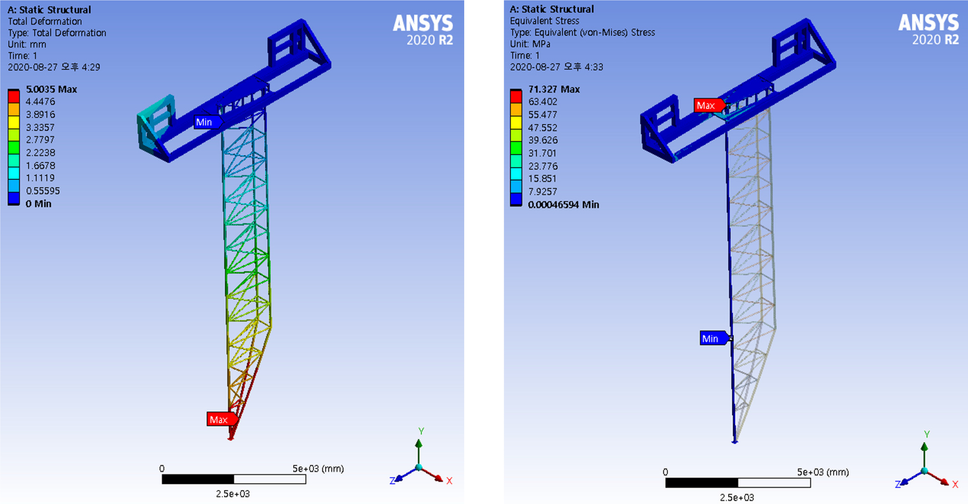
Under the 1 m/s condition, the highest pressure of 525 Pa occurred on the front surface center of the vertical frame of the current measurement jig and on both ends owing to flow separation, and a similar level of 515 Pa occurred on the front side of the reinforced truss frame. Based on the pressure distribution obtained from the CFD analysis under the 1 m/s condition, a structural analysis was performed, of which the results are shown in Table 2 and Fig. 5.
Based on the structural analysis, the safety factor was approximately 2.8 times the yield strength (205 MPa) of the STS304 pipe, i.e., a member of the current measurement jig; moreover, the deflection was 5 mm, which was approximately 1/3000 the total frame height. The expected maximum flow velocity with the impeller operating at the maximum rotational speed of 592 revolutions per minute (RPM) was 0.5 m/s in the surface layer, and the velocity decreased rapidly with depth. As the measurement jig was designed to withstand up to 1 m/s of uniform flow velocity, the strength of the jig was considered to be sufficient. In addition, the extremely small deflection of the jig implies that the position change of the measuring sensor will be small. Accordingly, the design structure was confirmed, and the assembled jig is shown in Fig. 6.
2.3 Current Measurement Sensor
A number of current sensors for the current measurement have been reviewed; however, ultrasonic waves were used in most current measurement sensors, i.e., a method based on the Doppler effect. Hence, particles must be present inside the fluid to enable measurement. However, the model test basin uses clear water, where particles are almost non-existent; therefore, the current measurement sensors available for this study were limited. Table 3 shows a comparison of two types of current measurement sensors.
The comparison shows that the Nobska MAVS4 model demonstrated better response time and accuracy; however, it was considerably larger than the Kenek VM-1001RS model. The sensor to be installed on the current measurement jig for measurements should be small to reduce fluid load and disturbance on the current flow field; therefore, the Kenek VM-1001RS model was selected. It is a sensor that measures the flow velocity based on the change in the electromagnetic field as well as measures three-dimensional flow directions. Its measurement accuracy is 0.02 m/s within the measurement range of ±1 m/s. All signals are in 2 Hz frequency; therefore, the measurements were obtained in 0.5 s intervals. Fig. 7(a) shows the sensor, and Fig. 7(b) shows the sensor attached to a jig that was temporarily laid down. Fig. 7(c) shows the three attached measurement sensors used for actual measurements.
3. Analysis of Current Measurement Results
3.1 Vertical Space Distribution Inside Basin
After installing the current measurement jig onto the tank, all the impellers were operated at maximum speed of 592 RPM, and the current flow velocity was measured at the center of the basin (pit center); the results are shown in Fig. 8. The rotational speed was increased in intervals of 100, 200, 300, 400, 500, 592 RPM. In the initial stage of the graph within 2,000 s, a stairstep graph was observed, whereby the fluid velocity remained flat while the rotational speed RPM was maintained at the same level for approximately 5 min. When the RPM of the current impeller was changed, the fluid velocity converged to a new velocity almost instantaneously. The current velocity stabilized in a short duration. This measurement was performed for more than 4 h at the maximum RPM. After 2,000 s, a constant current velocity was maintained without any significant change. At the maximum RPM, the maximum velocity was measured to be approximately 0.56 m/s in the surface layer.
For frequency analysis, Fig. 9 shows the spectrum matching of the velocity time series measured in the maximum RPM test shown Fig. 8 for the 3,000–15,000 s range, where the velocity stabilized and the acceleration and deceleration excluded sufficiently. From each velocity time series, the mean component was removed to conceal the zero-frequency component. In the surface layer (0.1 m), the variation component was small, and a specific frequency component that was relatively larger did not exist. At a depth of 3.1 m, the energy component was large at a frequency of 0.2 rad/s or less. Although no specific resonance frequency existed, a long-cycle vibration component of 30–200 s appeared. This vibration component will not affect the ships and offshore plants that are floating on the surface; however, it will affect slender structures such as mooring lines that are located deep in the water. Therefore, further investigations are necessitated.
During low velocity or deceleration, such as from 200 to 100 RPM, a longer time was required to stabilize the current velocity. Nevertheless, in all cases, sufficient current velocity stabilization was achieved, enabling the model test to be performed within 20 min after reaching the target RPM.
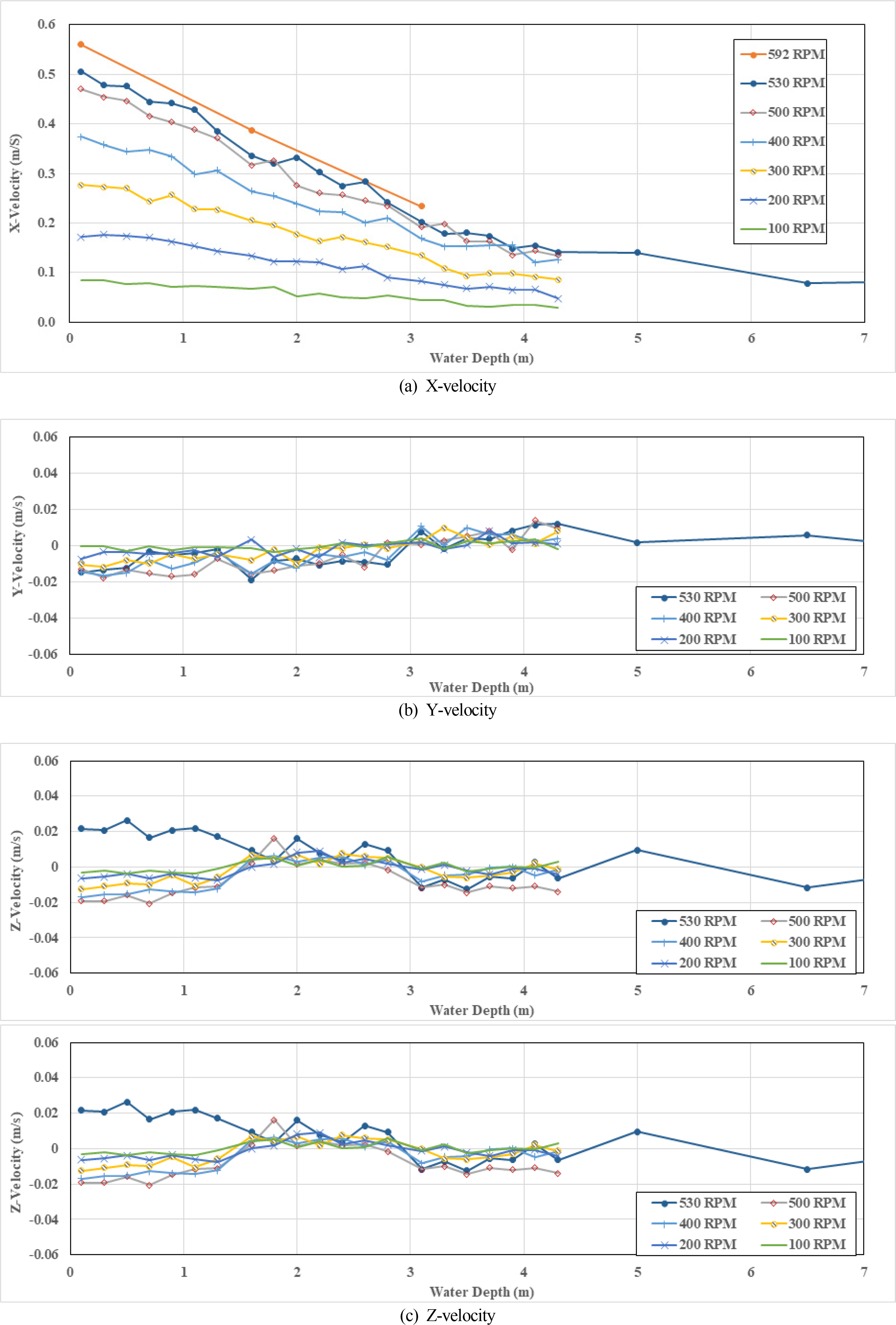
Fig. 10 shows the current velocity measurements at the center of the basin for various depths and RPMs. As mentioned earlier, the surface layer (0.1 m) velocity was approximately 0.56 m/s when all the current pumps were operating at a maximum rotational speed of 592 RPM. This exceeded the initial design target velocity of 0.5 m/s of the current generating system, thereby indicating sufficient performance. For example, in a model test of the offshore plant, which is considered to be the most general, if the model ratio is 1/50, then a model speed of 0.5 m/s would translate to an extremely high velocity of approximately 3.5 m/s on an actual ship. Therefore, all current velocities applied to marine structures can be reproduced.
By interpolating the result at 500 RPM and the velocity at 592 RPM, a 0.5m/s surface layer velocity was expected to be achieved at approximately 530 RPM; therefore, the velocity profile was measured up to a depth of 12.4 m for only 530 RPM. In general, the change in the RPM resulted in a relatively constant change in the velocity. Up to a depth of 4 m, the velocity gradient was almost linear with the depth. The RPM condition was the same for all duct layers; however, a low speed was measured in depths of 5 m and less owing to the large area of the outlet at the fourth, fifth, and sixth layers, i.e., the lower parts of the current generator.
The velocity on the Y- and Z-axes was close to 0, and only extremely small velocities were measured. This implies that the straightness of the flow was obtained in the targeted direction. Although the velocity was less than 0.002 m/s, i.e., significantly lower than the accuracy of the measurement sensor, the sign trend changed at intervals of approximately 1.5 m. Because the three sensors were installed on the measurement jig in 1.5 m intervals, the abovementioned phenomenon was regarded as a consequence of a minute error in the sensor installation angle, not as an actual flow velocity phenomenon. Considering the mounting angle error and measurement error, the mean velocity component on the Y- and Z-axes was non-existent.
Fig. 11 shows the turbulence intensity by depth. The turbulence intensity, TI, is expressed as shown in Eq. (1).
Here, σ is the standard deviation of the velocity, and V is the average current velocity. In the surface layer, the turbulence intensity was measured to be 5%–7%. Furthermore, the turbulence intensity increased with a constant slope up to approximately 4 m in depth.
As shown in Fig. 11, the flow was directed upward from the bottom to the surface. In addition, the inlet was segmented into six layers, and the inlet became narrower toward the upper layers, causing the velocity to be highest in the surface layer. As the flow ejected rapidly from the discharge port and coincided with the free water surface, it dissipated and stabilized. Therefore, almost no spatial velocity gradient was observed in the surface layer, resulting in insignificant velocity fluctuations.
For the lower velocity fluctuations (lower turbulence intensity), it will be difficult to reduce the porosity of the already installed perforated side wall; however, it will be relatively easy to install additional rectifying devices such as a screen at the discharge port. This will enable a constant flow velocity, but the velocity performance will decrease due to pressure loss.
3.2 Horizontal Spatial Distribution of Current Velocity
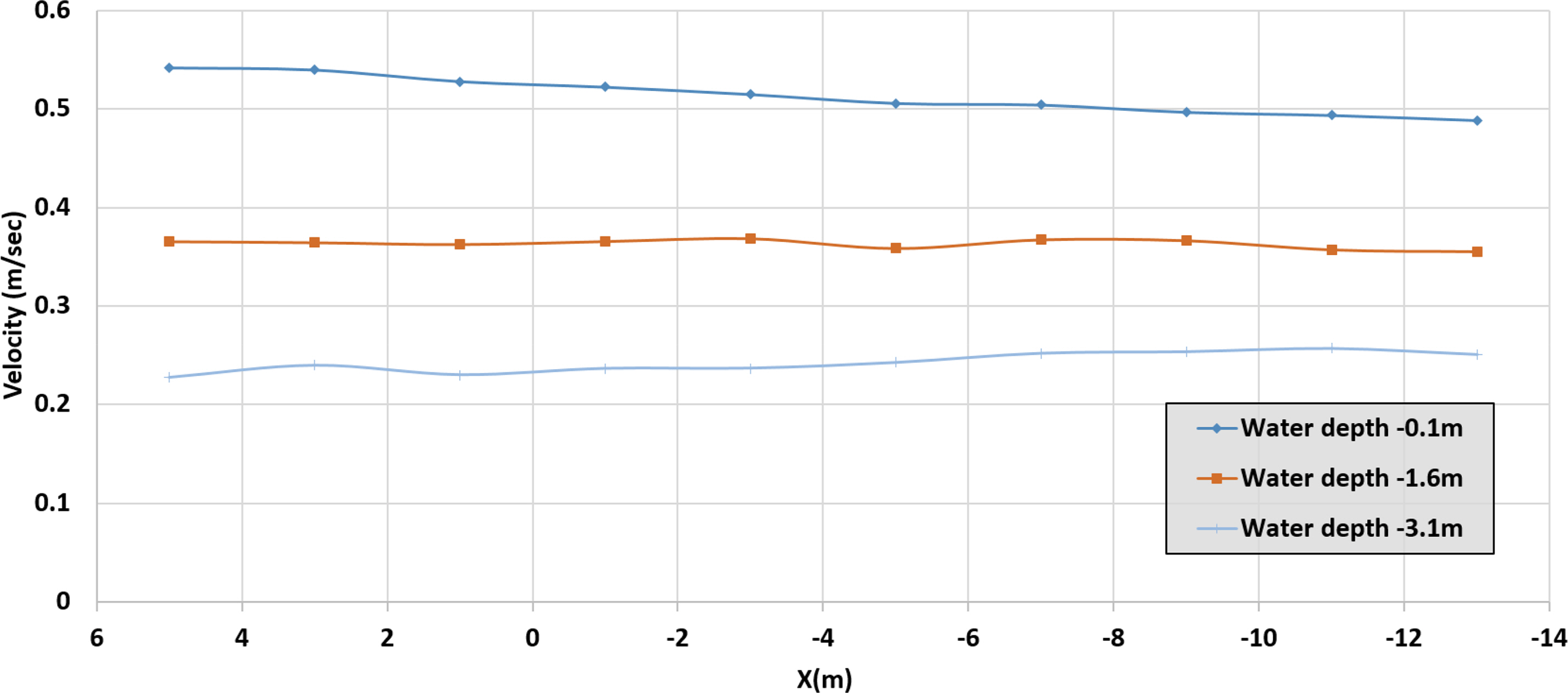
As previously mentioned, the initially designed target velocity of 0.5 m/s was expected to be achieved by applying a rotational speed of 530 RPM; therefore, the vicinity of the center of the basin was measured at 2 m intervals. Fig. 12 shows the trend in velocity change as the flow moved from upstream to downstream. In general, a target velocity of approximately 0.5 m/s was measured, with the surface layer velocity being high upstream (near x = 5 m) and decreasing downstream. In the graph, the position of the origin is the center of the pit, and the direction of the axis is shown in Fig. 1(b). It is noteworthy that a different trend was shown in deep water. At a depth of 3.1 m, the velocity increased slightly downstream. This is considered to be due to the velocity gradient stabilizing as the high velocity flow in the surface layer became mixed downstream.
A peculiar phenomenon was also observed from the Y-axis. As shown in Fig. 13, the velocity increased and decreased at regular intervals. This trend was observed in the preliminary CFD analysis at the designing stage, but the effect was excessive in the actual measurement. It was observed that the velocity increased and decreased in 5 m intervals, which is equivalent to the distance between the vertical walls at the discharge port (Fig. 1(b) shows the vertical wall location). The flow velocity was expected to decrease at the vertical wall due to viscosity; however, a higher velocity was measured. The cause was investigated and shown in Fig. 14. The velocity decreased at the vertical wall near the discharge port, resulting in a velocity gradient. However, the vorticity in the opposite direction (Z-axis vorticity) to offset this velocity gradient occurred from a distance of 10 m or more from the discharge port, and this rotational component might have increased the flow velocity (i.e., a momentum surfeit).
Other measurement results confirmed that it is advantageous to perform tests slightly downstream from the center of the basin (or pit center) to obtain a more even distribution of the current velocity. However, for some tests that require the 50 m depth of the pit, those tests can only be conducted at the center. In addition, the quality of the waves is expected to be better at the center rather than downstream. Therefore, the appropriate test location must be determined based on the characteristics and purpose of the offshore plant model test, such as the wave quality, current uniformity, and pit utilization. In this study, we obtained sufficient current distribution results from the model test; however, whether more rectifying devices can be added to the discharge port to achieve a more uniform current distribution should be investigated.
4. Conclusion
In this study, an efficient current velocity measurement jig was designed and assembled to verify the performance of a current generator in a deep ocean engineering basin. The jig was a 15-m-high triangular-truss structure, and the measurement sensor can move along the entire 15 m section through an electric motor-wire device. Fluid load and structural stability analyses were performed, and measurements were performed without significant deflection or deformation even at a current velocity of 1.0 m/s. Using this device, the performance of the current generator of a deep ocean engineering basin was confirmed, and the operation method and limitations of the current generator for future offshore plant performance verification model tests were summarized.
The current velocity was measured in various vertical and horizontal positions. The velocity profile by depth was derived from various rotational speeds including the maximum driving speed of 592 RPM. A maximum velocity of 0.56 m/s was achieved in the surface layer, and all current conditions required for the offshore plant model test within a realistic range were achievable. The variation component of the current velocity over time, which can be represented as an index of turbulence intensity, was confirmed. A turbulence intensity of 5%–7% for each RPM was confirmed in the surface layer, thereby ensuring sufficient uniformity in the model tests.
An additional turbulence control device can be installed at the discharge port to reduce the variation component over time and to obtain a more homogeneous current. In such a case, a decrease in velocity due to pressure loss is expected; therefore, an optimal turbulence control device must be developed. The variation component by area and the main cause were identified, and it was discovered that the velocity fluctuation occurred primarily around the vertical wall at the discharge port. By further investigating the flow control device at the discharge port, improvements in the spatial distribution and homogeneous currents are expected.
Acknowledgements
This study was conducted through the main project of the Korea Research Institute of Ships & Ocean Engineering (KRISO), “Development of the performance evaluation technology for standard offshore structures based on deep ocean engineering basin” (PES3920).

