Numerical Study to Evaluate Course-Keeping Ability in Regular Waves Using Weather Vaning Simulation
Article information

Abstract
Since the introduction of the mandatory energy efficiency design index (EEDI), several studies have been conducted on the maneuverability of waves owing to the decrease in engine power. However, most studies have used the mean wave force during a single cycle to evaluate maneuverability and investigated the turning performance. In this study, we calculated the external force in accordance with the angle of incidence of the wave width and wavelengths encountered by KVLCC2 (KRISO very large crude-oil carrier) operating at low speeds in regular waves using computational fluid dynamics (CFD). We compare the model test results with those published in other papers. Based on the external force calculated using CFD, an external force that varies according to the phase of the wave that meets the hull was derived, and based on the derived external force and MMG control simulation, a maneuvering simulation model was constructed. Using this method, a weather vaning simulation was performed in regular waves to evaluate the course-keeping ability of KVLCC2 in waves. The results confirmed that there was a difference in the operating trajectory according to the wavelength and phase of the waves encountered.
1. Introduction
With increasing environmental concerns worldwide, the Maritime Environment Protection Committee (MEPC) of the International Maritime Organization (IMO) introduced the mandatory energy efficiency design index (EEDI) to regulate greenhouse gas emissions from ships. However, there have been cases where the EEDI is satisfied by reducing the engine power of the ship, which may result in insufficient thrust required to maintain maneuverability in adverse conditions (SHOPERA, 2016). Therefore, the MEPC introduced guidelines for the minimum horsepower required to maintain maneuverability in adverse conditions (MEPC, 2013); these guidelines are still under discussion. Since studying maneuverability in waves was selected as the main task of the 28th International Towing Tank Conference (ITTC) maneuvering committee, there has been an increased need for research on methods for analyzing maneuverability in waves. Accordingly, studies estimating the maneuverability in waves are being conducted internationally by the joint European projects SHOPERA (SHOPERA, 2016) and SIMMAN (SIMMAN, 2020).
Numerous related studies have been conducted on predicting maneuverability in waves. Not only is there additional resistance caused by the waves, but forces form swaying oscillations or yaw motions that act on a ship as external forces. Various studies have been conducted to reflect the influence of these external forces in a mathematical model of the maneuvering motion. Yasukawa and Faizul (2006) experimentally determined the average wave force on SR108 operating in oblique sea conditions. Xu et al. (2007) performed a pure sway test in waves and proposed a method of testing the planar motion mechanism (PMM) in waves by analyzing the results. Cura-Hochbaum and Uharek (2016) conducted a study to reflect the influence of waves by pre-calculating the wave forces from various angles, digitizing them, and reflecting them in a simulation.
Yasukawa et al. (2018) examined the effectiveness of the zero-speed three-dimensional panel method (3DPM) and the strip theory-based Kochin-function method (SKFM) in calculating the wave force by comparing the results with experimental ones. Moreover, the estimation of the turning motion in irregular waves was validated by comparing the simulation and model test results using the wave force in irregular waves obtained using the 3DPM and SKFM. Seo et al. (2018) used a method of substituting the wave drift force as the external force in the maneuvering equation of motion. To this end, the advancing speed, the direction of the incident wave, and the wave force according to the wave length were calculated in advance and converted into a database to extract values suitable for simulation. In addition, the effect of the wave drifting force on the turning trajectory and turning parameters was studied based on a sensitivity analysis of the wave drift force. Additionally, a study was conducted to confirm the change in the maneuvering characteristics in waves using a free running model test rather than the mathematical model of maneuvering motion. Sprenger et al. (2017) observed the difference in the additional resistance among waves according to the depth by changing the depth and wave length for a tanker line and a container ship and examined the changes in the wave drifting force acting on the hull according to the water depth in oblique sea conditions. A free running model test was performed in waves to examine the change in the trajectory during a turning test according to the direction of the incident wave. Kim et al. (2019) evaluated the turning characteristics of KVLCC2 (KRISO very large crude-oil carrier 2) by performing a free running model test in regular waves. The free running model test was performed by changing the wave incidence angle and wave length, and the results were compared with those showing the trajectory of the free running model test in calm water.
As described above, many studies have been conducted to estimate the maneuverability in waves by using the wave force in the mathematical model of maneuvering motion in waves. However, most studies have evaluated the influence of the wave force using an average value and have not considered the change in external force according to the phase of the wave encountered by the ship. Additionally, most studies have focused on the change in the turning trajectory; however, weather vaning must be investigated to maintain the maneuverability of the ship in adverse conditions. Weather vaning is a movement in which the bow faces the direction of an incident current, wave, etc., and it plays an important role in preventing overturning due to the rolling motions in waves.
This fundamental study focuses on how to evaluate ship-handling safety in adverse conditions, in which the course-keeping ability of the ship in regular waves has not been evaluated. For this, the external force of the wave for the forward velocity was calculated using computational fluid dynamics (CFD) for an incident angle of 15° to 45° from the bow wave. The calculated external wave force was compared with model test results published in other studies. In addition, a simulation of the maneuvering motion was performed using the calculated wave force and maneuvering hydrodynamic coefficients published in previous studies. At this time, the wave conditions of regular waves were determined by referring to the revised guidelines of the MEPC 71st draft (MEPC, 2017). Simulations for the course-keeping ability evaluation were also performed in head sea and oblique sea conditions at an angle of 30° in the forward direction as specified by the MEPC guidelines to examine the course-keeping ability through weather vaning and the heel angle during the simulation.
2. Maneuvering Equation of Motion
2.1 Coordinate Systems
The coordinate systems used in this study are the Earth-Centered-Earth-Fixed (ECEF) coordinate system and the body-fixed coordinate system, as shown in Fig. 1. The origin of the x- and y-axes of the body-fixed coordinate system is taken as the center of the hull, and the bow direction of the ship is defined as the x axis; the direction perpendicular to the starboard is defined as the y axis; and the direction toward the bottom of the ship is defined as the positive (+) direction of the z axis. The spatial coordinate system defined the initial travel direction of the ship as the x direction (Kim, et al., 2016).

Coordinate system
2.2 Mathematical Model for the Maneuvering Motion in Waves
In this study, as shown in Eq. (1), the influence of waves derived by numerical calculations was considered as an external force on the mathematical modeling group (MMG) type mathematical model used for the analysis of turning performance in calm water to build a simulation model of turning in regular waves. The left side represents the maneuvering equation of motion for the surge force, sway force, and yaw moment, in order, and the right side represents the hydrodynamic forces by the hull, rudder, propeller, and external forces. The m on the left side denotes the mass of the ship; Iz denotes the moment of inertia; u denotes the longitudinal velocity; v denotes the lateral velocity; r denotes the bow rotation angular velocity; and the point marked on each velocity denotes the acceleration. The X on the left side denotes the longitudinal force; Y denotes the lateral force; N denotes the yaw moment; and the point marked on each velocity denotes the acceleration; the subscripts H, R, and P denote the hull, rudder, and propeller, respectively, and the subscript W denotes the wave force. Here, the wave force is defined as the difference between the hydrodynamic force acting on the hull in waves and in calm water.
The hydrodynamic force acting on the hull is expressed as Eq. (2), and it is nondimensionalized using the density, length between perpendiculars, draft, and advancing speed, as given in Eq. (3). Both the influence of plane motion and the influence of the moment acting on the hull according to the heel angle are considered in the hydrodynamic force acting on the hull. The hydrodynamic coefficients used to calculate the hydrodynamic force acting on the hull are shown in Table 1.
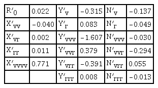
Hydrodynamic force coefficients used in simulations
The hydrodynamic force caused by the propeller was considered as in Eq. (4), and the hydrodynamic force caused by the rudder was reflected using Eqs. (5) and (6). The flow velocity flowing into the rudder in Eq. (6) is reflected by the difference between the flow velocities flowing into the rudder in waves and in calm water using the value obtained from the calculation of self-propulsion.
Eq. (7) is the equation of the rolling motion in waves. Each of the coefficients employed is expressed as Eq. (8) using the equation for estimating the roll damping coefficient published in a study by Seok et al. (2016).
The meanings of the symbols used in the above Eqs. (4)–(8) are shown in Table 2 below.
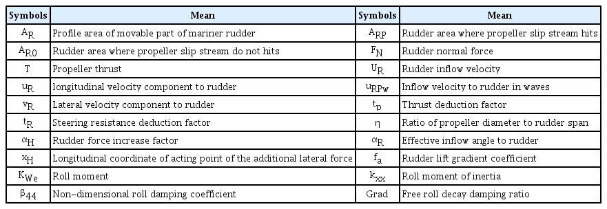
List of symbol
3. Conditions for Wave Force Calculation
3.1 Target Ship
KVLCC2 (SIMMAN, 2008) was selected as the target ship, and numerical calculations were performed on a 1:58 scale. The main specifications of the model ship are shown in Table 3. The testing with the hull alone at the speed of Fn = 0.037 was based on the speed in adverse conditions proposed by the MEPC 65th interim guideline.

Principal dimensions of KVLCC2 model ship
3.2 Conditions for Virtual Captive Model Test
This study used the commercial CFD software STAR-CCM+, which was proven to be useful in the study by Simonsen et al. (2012). The computational domain that was formed to perform numerical calculations is as shown in Fig. 2. From the midship, it was set as 1.5 times the length of the hull toward the inlet boundary, 2.5 times the length of the hull toward the outlet boundary, twice the length of the hull to the side boundaries, the length of the hull toward the top boundary, and 1.5 times the length of the hull toward the bottom boundary.
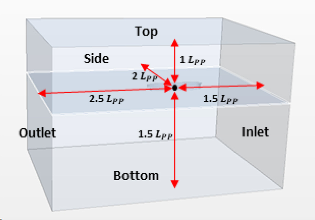
Computational domain
To create the grid, the trimmed mesh and prism layer techniques provided by STAR-CCM+ were used. The size of the trimmer grid was set to be relatively small in the free water surface and around the hull, and it was relatively large in the simple flow region. The prism layer technique was used to accurately calculate the prism layer flow on the hull surface, and a total of four prism layers were created from the hull surface. The thickness of the first prism layer grid from the hull surface was defined with the value and was within the range of 40 to 70. Dynamic fluid body interaction (DFBI) and overset mesh techniques were used to consider the effect of changes in posture according to the wave, and as shown in Fig. 3 a total of approximately 4.3 to 5.2 million grids were generated.
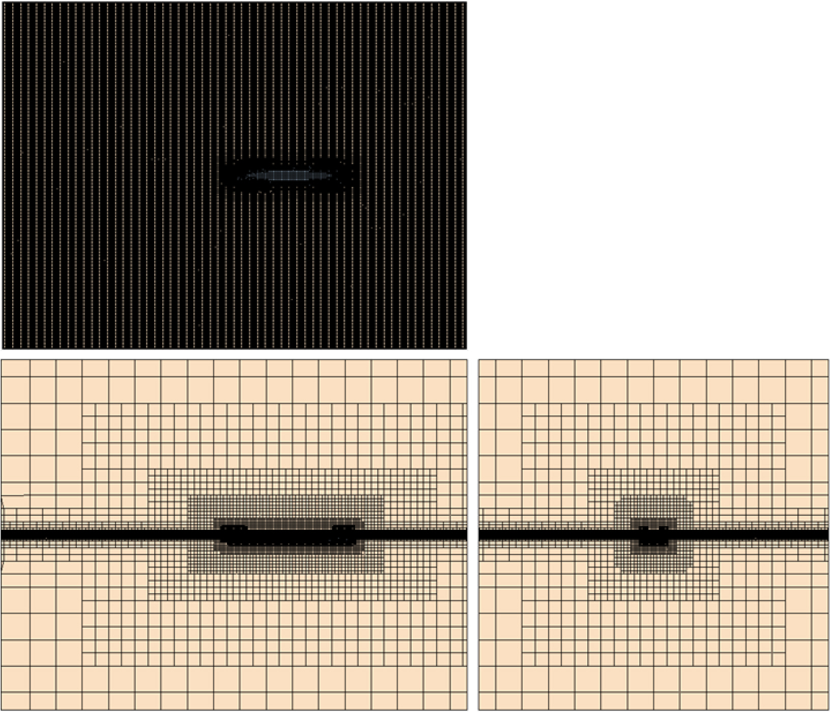
Volume mesh
Free water surface was considered by using the volume of fluid (VOF) technique, and the realizable k-ε (RKE) model was used as the turbulence model to ensure the stability and efficiency of numerical calculations. Unsteady condition analysis was performed for the dynamic analysis of the hull. A first-order implicit method was used for temporal discretization, and a second-order up-wind scheme was used for spatial discretization. The boundary conditions for the CFD calculation used in this study are shown in Table 4.
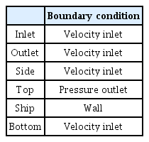
Boundary condition
Infinite depth was configured by setting the inlet boundary of the computational domain as a velocity inlet, the top boundary as a pressure outlet, and the outlet, bottom, and side boundaries as velocity inlets. In addition, the wave forcing feature provided by STAR-CCM+ was applied to the section of one time of the length between perpendiculars from each of the inlet, outlet, left and right boundaries to minimize the influence of reflected waves.
3.3 Verification of Wave Generation
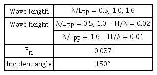
The wave conditions used in this study are shown in Table 5 below. For the regular waves used in this study, the wave height was determined by setting the wave slope to H/λ = 0.02 at λ/Lpp = 0.5,1.0; and the wave condition was determined by setting the wave height was determined by setting the wave slope to H/λ = 0.01 at λ/Lpp = 1.6, according to the ITTC recommended procedure and guideline (ITTC, 2014). The wave incident angle to be used in the maneuver simulation in waves was determined by employing the weather vaning wave incident angle (30° from the bow wave) proposed in the 71st draft revised guidelines of MEPC.

Wave condition
In order to verify the waves generated using CFD, verification was performed using theoretical waves. The wave was created using the Stokes order wave theory, the wave length of the incident wave used for verification was, λ/LPP = 1.0 the wave height was H/λ = 0.02, and the period at this time was about 1.31 s for the model ship. The grid conditions used to generate waves were set based on the study by Kim. (2019), with 60 gratings per wave length in the x direction, 20 gratings per wave height in the z direction, and the aspect ratio of the grid in the x-direction to the grid in the y-direction is 1:4. Wave calculations were performed for a total of 10 cycles with 20 internal iterations. The time interval was designated to allow 500 calculations per wave cycle. Fig. 4 represents the difference from the theoretical waves generated by CFD for 10 cycles, and Table 6 shows the difference from the theoretical crest and trough values for five cycles. The generated waves showed an error of −4.33% from the theoretical waves at the wave crest, and −4.02% at the trough.
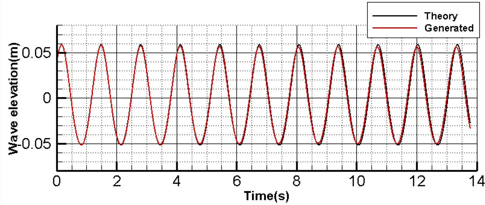
Comparison of Stokes 5th order wave and generated wave (λ/Lpp = 1.0, H/λ = 0.02)

Difference between generated wave and Stokes 5th order wave
3.4 Review of Grid Convergence
Prior to calculating the wave force acting on the hull in regular waves, a convergence review was performed on the generated grid system. Grid convergence was reviewed with a grid strain of according to the ITTC recommended procedure and guideline (ITTC, 1999). The size of the grids corresponding to the fine, medium, and coarse grids is shown in Table 7 below. Surge, sway force and yaw moment, and convergence ratio for each grid are shown in Fig. 5 and Table 8.

Information related to different types of grids for convergence test

Non-dimensional surge, sway force and yaw moment

Predicted convergence ratio
As a result of examining the grid convergence, the calculated result values converge as the number of grids increases. In this study, numerical calculations were performed on the forces and moment acting on the hull in regular waves based on the grid size applied to the densest grid system.
4. Results of Wave Force Calculation
Fig. 6 shows the average value of the wave force according to the angle of incidence for each wave length obtained by CFD calculation. Except for the resistance generated during operation in calm water, only the external force corresponding to the additional resistance was expressed as the surge force, and each of the forces and moment was made nondimensionalized using Eq. (3). The surge force was relatively low with a low wave height at λ/L = 0.5, the sway force was the highest with a long wave length, and the yaw moment was the greatest at λ/L = 1.0.

Wave force according to wave length
Fig. 7 shows the wave shape around the hull calculated at angles of incidence of 180° and 150°. The height of the free water surface was nondimensionalized using the wave amplitude. The wave shape around the hull appears more clearly at the short wave length than at the long wave length as it is easier for the wave to penetrate the hull with the longer wave length.

Free surface distribution at head sea / incident angle 150°
Fig. 8 shows the results of the comparison with the S-Cb84 linear model test results reported by Yasukawa et al. (2018). Direct comparison with KVLCC2 was not possible because there was no published model test result performed at low speed. As the depot ship of S-CB84 is KVLCC1, the result of the wave force acting on the hull of S-CB84 was believed to be similar to that of KVLCC2; the comparison was performed under such an assumption. The black points in the figure are the additional resistance 및 lateral force, the yaw moment acting on S-Cb84 measured under the condition of Fn = 0.049 and wave height = 3.1 m (solid line), and the points indicate the results of the CFD calculation in this study. The forces and moment were nondimensionalized using the wave height, length of the hull, and width of the hull, as shown in Eq. (10). Similar trends appeared when comparing the forces and moment according to the wave length. The weather vaning simulation was performed using the calculated wave force.

Comparison of wave force based on CFD results and model test results
5. Weather Vaning Simulation in Waves
5.1 Conditions for Weather Vaning Simulation
In this study, a weather vaning simulation considering the phase of waves encountered with the hull was proposed for the evaluation of the course-keeping ability in waves. The simulation was performed in head sea and oblique sea conditions at an angle of 30° in the forward direction, according to the 71st draft revised guidelines of MEPC, in order to examine the course-keeping ability through weather vaning. The simulation conditions are as in Table 9, and the steering was performed from the moment when the wave was encountered at the midship after moving forward during the initial 5 s in calm water. The simulation was performed by dividing the phase of the wave encountered at the midship from the start of steering, as shown in Fig. 9. The results were compared with the simulation using the average wave force. When the heading angle reached the initial 30°, rudder angle control was performed to maintain the course. It was controlled by inverting the rudder to the maximum rudder angle based on the heading angle of 30°.
Weather vaning simulation condition
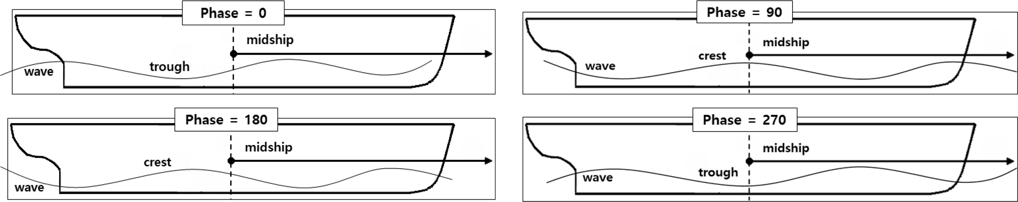
Wave initial condition – encountered wave phase at midship
With respect to the external wave force used in the simulation, the previously calculated time series data showing the result of calculating the wave force at incident angle intervals of 15° were reflected in the simulation through Fourier transform. The values in calm water from the study by Yasukawa and Yoshimura (2015) were used for the maneuvering hydrodynamic coefficients, and factors used in the simulation pertained to the propeller and rudder.
5.2 Results of Weather Vaning Simulation
Weather vaning simulations were performed to evaluate the course-keeping ability of KVLCC2 in waves. Figs. 10 to 13 show the results of the weather vaning simulation for 30° heading angle turning in calm water, and the 150° angle incident wave in waves showing the trajectory, heading angle, and heel angle according to the wave length. The heel angle from the motion was not considered for the simulation in calm water, and no result was obtained.
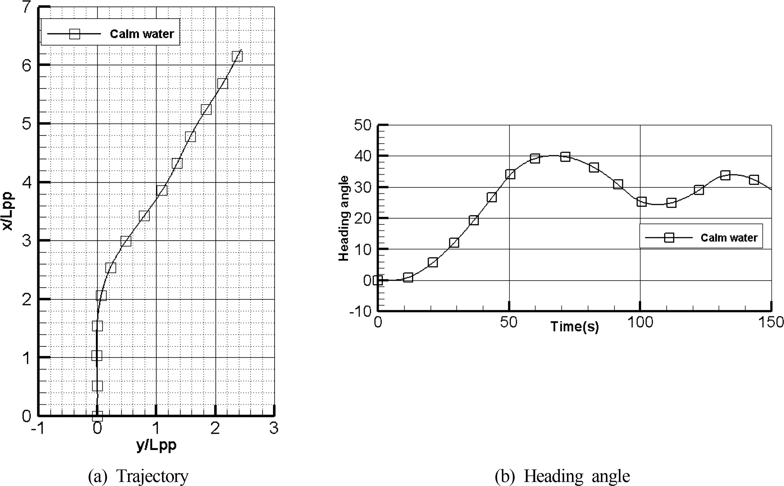
Heading angle for 30° turning simulation result in calm water
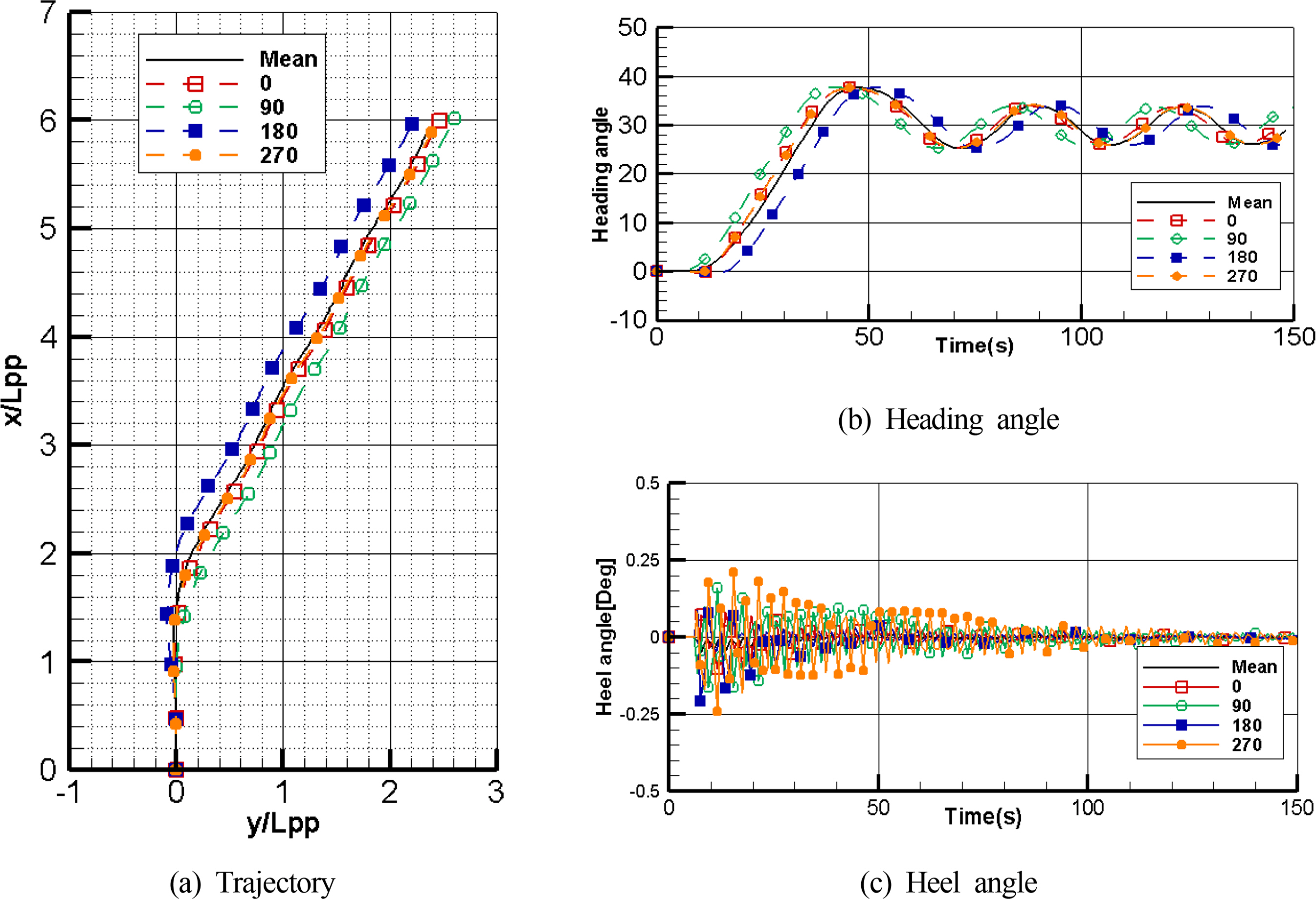
Weather vaning simulation result at λ/L = 0.5

Weather vaning simulation result at λ/L = 1.0

Weather vaning simulation result at λ/L = 1.6
The solid black line shows the simulation result obtained using the average wave force, and the other colored lines are the results of simulation by dividing the phase encountered from the start of steering, as shown in Fig. 9. With respect to the trajectory in waves, the moving distance varies depending on the wave length when it initially turns up to 30°, compared with the turn in calm water. In calm water, it was about 1.82LPP, but in waves, it was 1.42LPP at, 0.93LPP at λ/L = 1.0, and 1.01LPP at λ/L = 1.6. This may have been caused by the change in the number of propeller rotations according to the wave length to maintain the same advancing speed of 4 kn (1.85 km/h), and the rudder force increased with the increased number of propeller rotations against the relatively high additional resistance at λ/L = 1.0 and λ/L = 1.6, resulting in the fast turning. The trajectory also varied depending on the phase of the wave encountered at the start of steering.
With respect to the change in heading angle, turning occurs faster at λ/L = 1.0 and λ/L = 1.6, compared to the simulation in calm water. In addition, the tendency of the overshoot angle of the heading angle decreased in calm water and at λ/L = 0.5. Regular vibration is generated based as for 30° at λ/L = 1.0 and λ/L = 1.6. This appears to have been caused by the rudder control method to shift the rudder to the maximum rudder angle upon exceeding 0° from the heading angle, resulting in the overshoot angle at λ/L = 1.0 and λ/L = 1.6. The overshoot angle may be reduced by changing the controller, such as the proportional-integral-differential controller (PID) controller.
The maximum heel angle was about 3.71° greater at λ/L = 1.6 than at λ/L = 0.5, and about 2.48° greater than at λ/L = 1.0. The relative difference at each wave length was large, but the original absolute heel angle was not very large, which may have been because nature of the tanker did not cause much rolling motion.
When comparing the difference according to the phase encountered during initial steering, at λ/L = 0.5, there was a varying speed at which the heading angle changes according to the phase of the wave encountered during the initial steering, resulting in different initial trajectories. However, there was subsequently little influence during the steering to maintain the course. However, at λ/L = 1.0, the trajectory during steering to maintain the course varied depending on the phase of the wave encountered during turning as well as the initial steering. With respect to the phase = 270 simulation, an overshoot angle of up to 13.4° occurs from 30°. Even at λ/L = 1.6, there was a difference in the heading angle change depending on the phase of the encountered wave, and the maximum heel angle was greater than the result obtained from the simulation using the average wave force.
6. Conclusion
This study aimed to evaluate the course-keeping ability of KVLCC2 in regular waves by performing weather vaning simulations. Simulations were also performed in head sea and oblique sea conditions at an angle of 30° in the forward direction according to the MEPC 71st draft revised guidelines to examine the course-keeping ability through weather vaning against the incident waves.
To this end, the maneuvering equation of motion in waves using the wave force as the external force in the existing maneuvering equation of motion in calm water and the equation of the rolling motion in waves to calculate the heel angle in waves were configured. In addition, an equation was developed to consider the yaw motion according to the heel angle to the hydrodynamic force acting on the hull in order to determine the influence according to the heel angle in the maneuvering motion. The external force of the wave was calculated according to the incident angle using CFD, and external forces such as the surge force, sway force, and yaw moment were compared with the results of the similar ship model test. In order to reflect the influence of the phase of the waves encountered with the hull in addition to the average wave force, it was configured to change according to the phase using the Fourier transform.
The following conclusions were made by performing a simulation according to the phase change of the wave encountered with the hull using the simulation configured in this study.
Based on the evaluation results of for the course-keeping ability of KVLCC2, weather vaning was possible despite the differences in the trajectory and heading angle according to the wave length. The heel angle did not exceed the generally known stability range.
The results of the simulation obtained using the average wave forces was different from the results of the simulation considering the changes in external forces according to the phase of the waves encountered by the ship. The simulation results also differed according to the phase encountered initially.
The differences according to the phase of the wave were more profound with a long wave length than with a short wave length, which may have been caused by the increased wave height owing to the increase in wave length.
For a further evaluation of the maneuverability and course-keeping ability in high waves, a study considering the influence of the hull and the encountered phase will be required. It may also be necessary to consider the motion with 4 degrees of freedom or 6 degrees of freedom in addition to the plane motion generally used in studies of maneuvering motions.
Notes
This study was carried out with the support of “Experimental Study on the Development of Large Control Algorithm for Multiple Unmanned Ships (project number: 2020R1F1A1071610),” a basic research project of the National Research Foundation of Korea (NRF), and “Development of Autonomous Navigation System with Intelligent Route Planning System (project number: 20200615),” an autonomous ship technology development project of the Ministry of Maritime Affairs and Fisheries, Republic of Korea.