Feasible Positions of Towing Point and Center of Gravity for Towfish Attitude Control
Article information

Abstract
Most towfish systems do not have propulsive devices and cannot compensate for perturbation motion, which can affect the observation data. This paper discusses attitude control of a towfish with elevators on the left and right tail wings to improve the quality of the observational data. Specifically, we investigate the relationships between the towing point, the center of gravity, and the drag forces produced by the elevators to clarify whether the elevators can control the attitude of the towfish sufficiently for various positions of the towing point and center of gravity. The feasible positions of the towing point and center of gravity are defined by mechanical analyses, and simulations are conducted to verify that the elevators can provide attitude control in these positions. The simulation results show that at some positions, the elevators can control the attitude quickly and sufficiently even if disturbances exist.
1. Introduction
A towfish is moved by a cable connected to a mother ship because it does not have a thrust device (Go et al., 2016; Buckham et al., 2003; Isa et al., 2014). Because towfishes are usually convenient to operate and maintain, they have been used recently for underwater target detection and submarine resource detection in civil and military applications and have been operated with various types of sonar (Park and Shin, 2009; Song and Choi, 2016).
The shape of a towfish is designed to enable hydrodynamically stable movement, but towfish cannot always respond optimally to unforeseeable marine or underwater environments and some operating environments. In particular, when a towfish is equipped with a high-resolution sonar system such as interferometric synthetic aperture sonar (InSAS), which uses the phase differences of signals received by array sensors at different positions to obtain three-dimensional images (Lee et al., 2019; Kim et al., 2017), the irregular motion of the towfish causes distortion or defocusing of the InSAS images. To address these problems, the attitude of the towfish must be controlled (Park and Kim, 2015; Lambert et al., 2003; Kim et al., 2016; Choi et al., 2005).
Meanwhile, because the motion of the towfish is greatly affected by the cable connected to the mother ship, it is important to identify the optimal towing point. Consequently, the dynamic relationship between the center of gravity and center of buoyancy of the towfish must be analyzed. In particular, when the attitude is controlled using an actuator such as a propeller or an elevator, the analysis must consider the capacity of the actuator, in addition to the center of gravity and center of buoyancy.
In this study, dynamic analyses considering the towing point, center of gravity, center of buoyancy, and elevator capacity are conducted to investigate the attitude control of a towfish with elevators attached to its left and right horizontal tail wings. In addition, the results of these analyses are used to identify a method of selecting appropriate positions of the towing point and center of gravity. Here, the towing force acting on the towfish is assumed to be constant, taking into consideration the state in which the motion of the towfish is stabilized.
The contents of this paper are as follows. The equations of motion of the towfish for use in the dynamic analyses are presented in Section 2. A method of determining appropriate positions of the towing point and center of gravity for eight selected cases considering changes in the towing point and center of gravity is proposed in Section 3. In Section 4, attitude control using the equations of motion of the towfish is simulated to verify the validity of the obtained feasible regions of the towing point and center of gravity.
2. Mathematical Model of the Towfish
Fig. 1 illustrates how the towfish is connected to the mother ship through a cable and shows the forces acting on the towfish. Assuming that elevators are attached to the left and right horizontal tail wings for attitude control, the equation of motion of a towfish with six degrees of freedom can be expressed as follows, considering the elevator force, weight, and buoyant force, including the towing force from the cable:
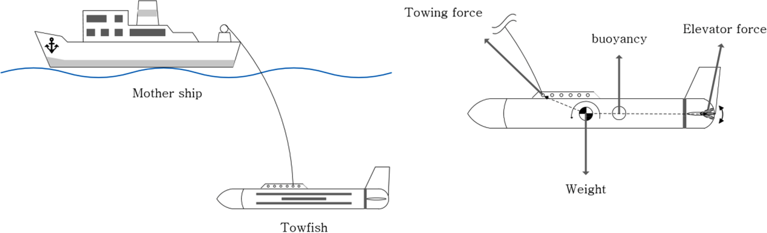
Towfish system and the forces acting on the towfish
The right-hand terms of Eq. (1) represent the forces and moments acting on the towfish. fc, fe ∈R3, and fb∈R 6 are the towing force from the cable, the elevator force, and the restoring force generated by the weight and buoyant force, respectively. rc and re∈R 3 are the position vectors from the center of gravity to the towing point and the elevator center, respectively, and × represents the vector product. If S (a) is a skew-symmetric matrix, the relational expression a×b=S(a)b, a, b∈R 3, is satisfied if a =(ax, ay, az )T, S(a) is given by
If the right-hand terms of Eq. (1) are defined as τ, τ is given by
3. Positions of the Towing Point and Center of Gravity
Fig. 2 shows the forces acting on the towfish in the xz plane. fc(xz)=(fcx, fcz )T and fe(xz) =(fex, fez )T are the towing forces and elevator forces in the xz plane, respectively. rc(xz) =(rcx, rcz )T and re(xz) = (rex, 0)T are the position vectors from the center of gravity to the towing point and to the elevator center, respectively. Using these variables, the pitching moment of the towfish generated by the towing force, restoring force, and elevator force in the xz plane can be calculated as
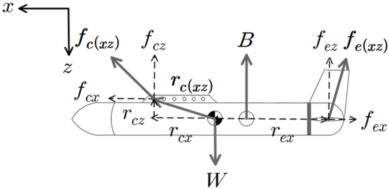
Forces acting on the towfish in the xz plane
Assuming that the motion of the towfish is stabilized and the forces are in equilibrium, the moment of the hydrodynamic force acting on the body is not included in Eq. (5), where fb5 is the fifth component of fb in Eq. (3). In addition, ⊗ is the vector product in the plane, and satisfies interaction formulas such as a⊗b=(Ea)T b=(ET aT)b, a,b∈R 2. Here E is a rotation matrix that represents rotation by 90° in the counterclockwise direction in the plane and is given by
Multiple cases must be analyzed because the direction and force of the pitching moment vary with the positions of the towing point, center of gravity, and center of buoyancy. In this study, the eight cases shown in Fig. 3 are analyzed.
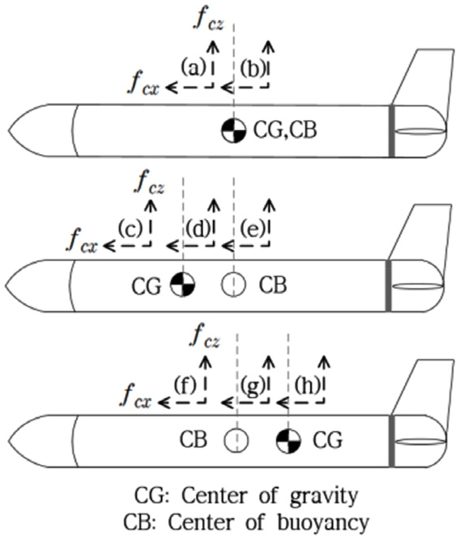
Eight cases [(a)–(h)] used to examine the effect of the positions of the towing point and center of gravity
3.1 Cases Where Only the Towing Point Changes [Cases (a) and (b)]
In cases (a) and (b), where the towing point is in front of and behind the center of gravity, the center of gravity and center of buoyancy are fixed at the same position. The effect of the restoring force term, fb5, can be ignored because the moments caused by the weight and buoyant force are not generated. rcx, which is in equilibrium with the maximum and minimum elevator forces in Eq. (5), is calculated using the Eq. (7) for cases (a) and (b). The maximum and minimum elevator forces, fez max and fezmin are defined as being generated at the maximum angles in the positive and negative directions. The positions of rcx, which can controlled by the elevator force, fez, according to Eq. (7), are shown in Fig. 4.
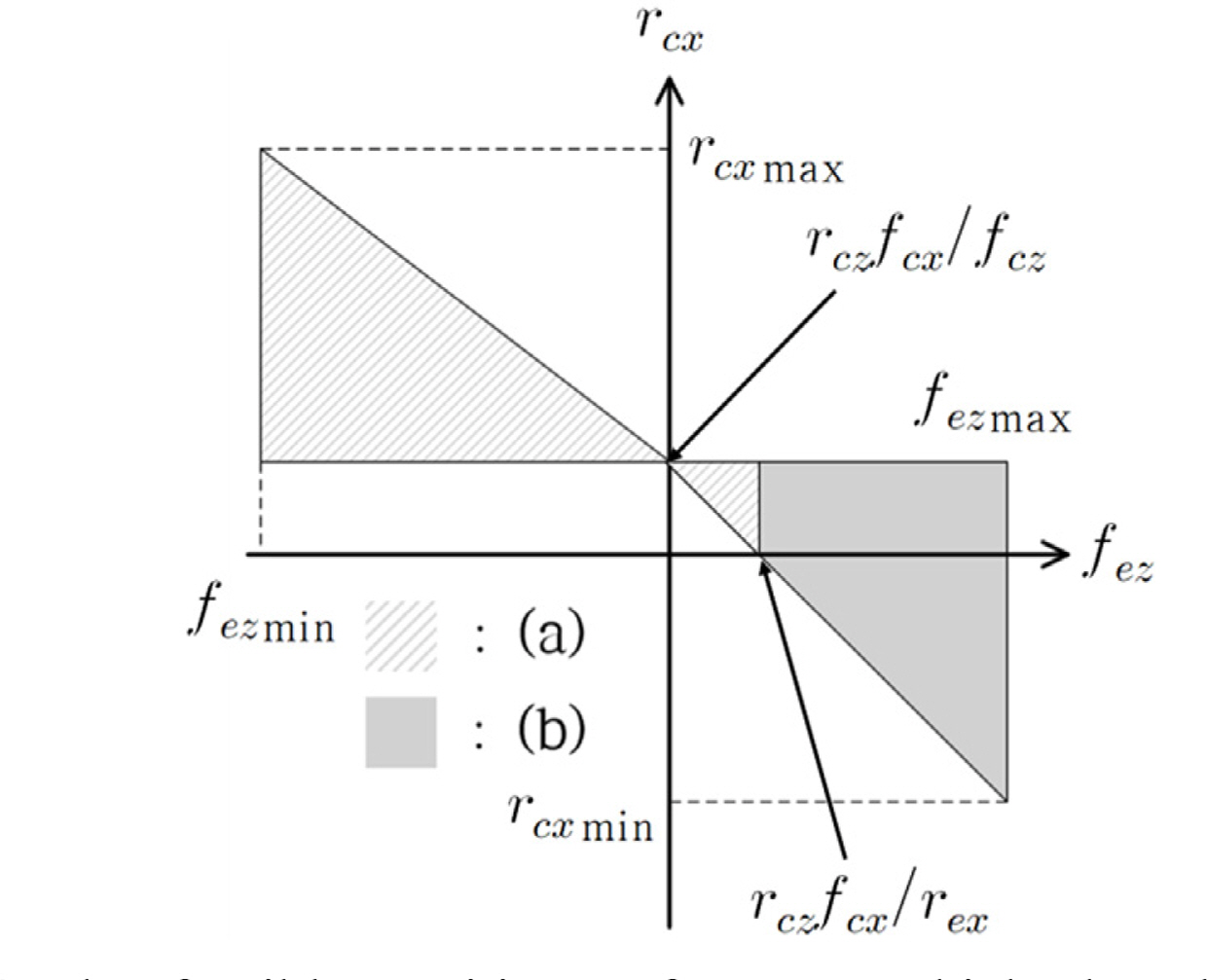
The feasible positions of rcx at which the elevators are able to control the pitching moment
The point at which rcx = rczfcx/fcz in the area corresponding to case (a) becomes the optimal towing point for maintaining the attitude of the towfish without an additional elevator force because rcz fcx is constant, even if rcx changes. The attitude becomes more difficult to control as the towing point, rcx, moves farther away from center of gravity because the elevator force required for attitude control increases.
3.2 Cases in which the Center of Gravity and Towing point Change [Cases (c)–(h)]
In cases (c)–(h), the center of buoyancy is fixed at the origin. The center of gravity is in front of the center of buoyancy in cases (c)–(e) and behind it in cases (f)–(h). Under these conditions, the areas of rcx and xg that can be controlled by the elevator force, fez are examined as follows.
The maximum and minimum towing points (rcxmax, rcxmin) are calculated in the case where the center of gravity and center of buoyancy are at the same position;
The maximum and minimum positions (xgmax, xgmin) of the center of gravity are calculated when the obtained maximum and minimum towing points and the center of gravity are on the same line of the z-axis;
The maximum and minimum towing points (rcxgmax, rcxgmin) at the maximum and minimum centers of gravity obtained in procedure (2) are calculated.
The restoring force term in cases (c)–(h) must be considered because, in contrast to cases (a) and (b), the center of gravity and center of buoyancy are at different positions. The restoring force term, fb5, is −(zgW − zbB)sθ −(xgW− xbB)cθcϕ and can be simplified to − xgW when the center of buoyancy is fixed at the origin and the towfish is stabilized (θ, ϕ≈0). The maximum and minimum towing points are obtained equally in Eq. (7) if procedure (1) is performed using Eq. (5) and the maximum and minimum positions xgmax, xgmin are calculated as follows if procedure (2) is performed:
Fig. 5 shows the feasible positions of the center of gravity and towing point at which the elevators can control the pitching moment according to the Eqs. (7), (8), and (9). The dotted line represents the points at which the pitching moment of the towfish is not generated, even when the elevator force is not generated. Most of these points appear at positions that correspond to cases (c) and (h); thus, the dotted line indicates advantageous positions for attitude control of the towfish. Conversely, the positions corresponding to cases (e) and (f) do not include the dotted line; thus, attitude control can be considered difficult in these cases.

Feasible positions of rcx and xg at which the elevators can control the pitching moment
4. Simulations
Simulations were performed to examine the relationship between the positions obtained in Section 3 and identify the control performance. The attitude of the towfish is controlled by the drag forces generated by the left and right elevators, which are given by the following equations:
Here, ρ, s, u, and α represent the density of water, the area of a single elevator, the velocity of the towfish, and the angle of attack, respectively. CD and CL are the drag and lift coefficients, respectively; their values were obtained according to the airfoil model of the National Advisory Committee for Aeronautics (NACA). Because the angle of attack is the same as the elevator angle, fex and fez are expressed as functions of the elevator angle (Park et al., 2016). If δl and δr are the angles of the left and right elevators, respectively, the pitch angle of the towfish can be controlled by following the value of the synchronous elevator angle, δS = (δr +δl)/2. The simulations were performed using the following equations of motion obtained from Eqs. (1) and (10).
Kp, Kd, and Ki are the control gains in a proportional–integral–derivative [PID] controller and represent the proportional, derivative, and integral gains of the elevator angle, respectively. θd and θ represent the target pitch angle (reference input) and current pitch angle, respectively. The values 0.065 and 0.11 used in Eq. (11) are the slopes of the drag and lift coefficients plotted for various elevator angles, respectively, and were linearized by referring to the values for the NACA 0018 model.
Table 1 lists the parameter values of the towfish used in the simulations. The towfish was assumed to be a horizontally symmetric cylinder, with a length and diameter of L and D, respectively. Iy is the moment of inertia of the towfish with respect to the y-axis. The other symbols represent hydrodynamic force derivatives (Fossen, 1994). Xu, Zw, and Mq were calculated using the towfish data, and Xu, Zw, Mq, X|u|u, Z|w|w, and M|q|q were selected on the basis of the simulations.
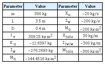
Parameter values used in simulation
4.1 Simulation Conditions
Table 2 shows the simulation conditions. W′ =W −B denotes the underwater mass. The control gains of the attitude-maintaining controller, Kp, Kd, and Ki, were set to 3, 5, and 0.01, respectively, and the left and right elevator angles were maintained within ±30° to ensure the stability of the towfish.
Simulation conditions
The simulations were performed by selecting sufficiently controllable positions and positions that are somewhat difficult to control according to the elevator capacity within the areas corresponding to cases (a) and (b), cases (e) and (f), and cases (c) and (h). Additionally, cases where disturbances are applied at arbitrary positions within the areas corresponding to case (c) (easy to control) and case (f) (difficult to control) were examined.
4.2 Simulations of Cases (a) and (b)
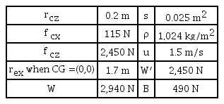
rcxmax ≈ 0.14 m and rcxmin ≈ −0.12 m are obtained from the conditions given in Table 2 and Eq. (5). The simulations were performed by selecting difficult-to-control cases for rcxmax and rcxmin and easily controlled cases with rcx = 0.02 m and rcx = −0.02 m, as shown in Fig. 4.
Fig. 6 is a simulation result showing the pitch angle and synchronous elevator angle of the towfish when a pitch angle of 0° is applied as the reference input for the four positions. The blue dotted and solid lines are the results of the simulations at points ● and ○ selected from the area for case (a), respectively. The red solid and dotted lines are the results of the simulations at points ▴ and ▵ selected from the area for case (b), respectively. The portions of the solid line indicated by ○ and ▵ represent the cases where the towing point is at rcxmax and rcxmin, respectively; they show that the target pitch angle (0°) of the towfish is reached very slowly, even at the maximum elevator angle (±30°). In these cases, even if the attitude of the towfish is controlled, it is difficult to address additional disturbances because there is little margin in the elevator angle. By contrast, the portions of the dotted line indicated by ● and ▴ are relatively easy to control, and the target pitch angle (0°) can be reached quickly. Moreover, the system can react immediately even when disturbances are applied because there is considerable margin in the elevator angle.
Pitch angles and δS (synchronous elevator angle) for cases (a) and (b)
4.3 Simulations of Cases (e) and (f) and Cases (c) and (h)
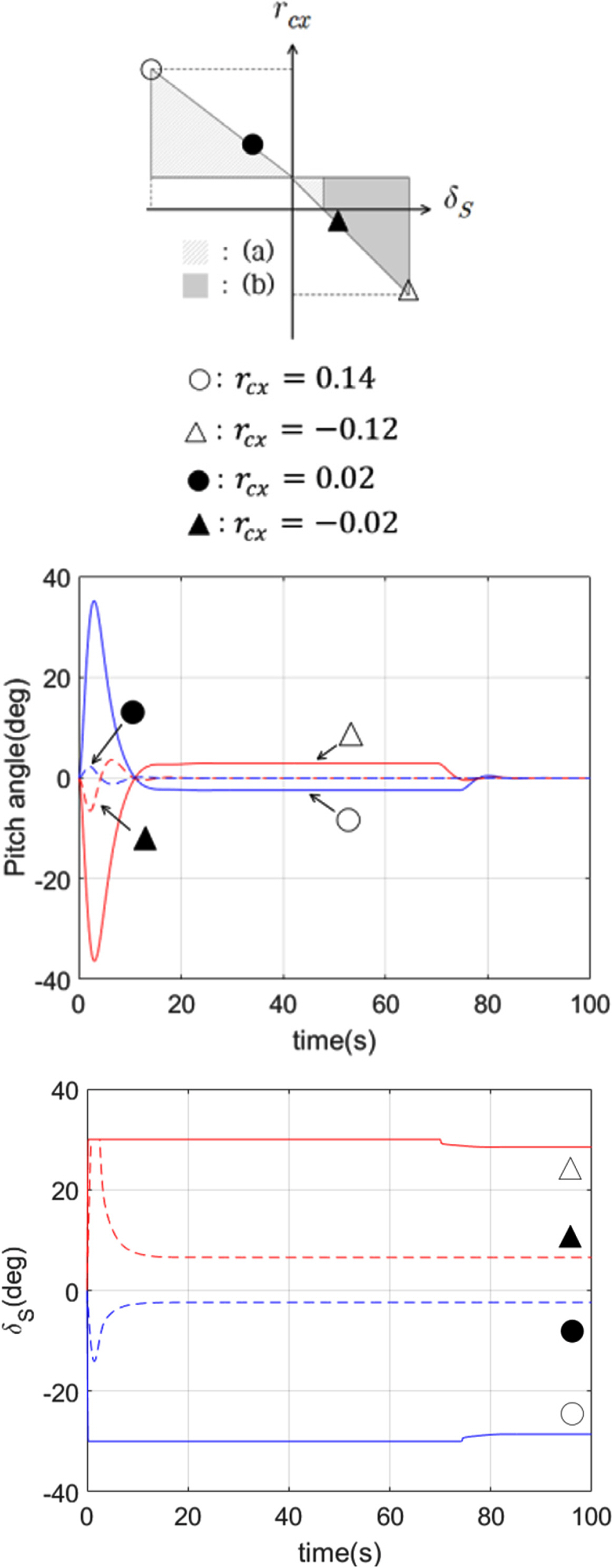
From the conditions given in Table 2 and Eqs. (8) and (9), the maximum and minimum positions of the center of gravity that the elevator can control are given by xgmax ≈ 0.1 m and xgmin ≈ −0.12, respectively. The maximum and minimum towing positions at this time are calculated as rcxgmin ≈ 0.27 m and rcxgmax ≈ −0.26 m. The simulations were performed by selecting cases (e) and (f), in which control is difficult, and cases (c) and (h), in which control is relatively easy. The values of rcx and xg for each case are listed in Table 3. Fig. 7 is a simulation result showing the pitch angle and synchronous elevator angle of the towfish when a pitch angle of 0° is applied as the reference input for the four positions shown in Table 3. The areas corresponding to cases (e) and (f) (positions ○ and ▵) have little margin in the elevator angle; therefore, the target pitch angle 0° is reached very slowly. In these cases, it is difficult to immediately address an additional disturbance. However, at the positions (▴ and ●) corresponding to cases (c) and (h), the target pitch angle is obtained quickly because there is considerable margin in the elevator angle. In these cases, it is possible to respond adequately to additional disturbances.

Positions of rcx and xg for cases (e), (f), (c) and (h)
Pitch angles and δS (synchronous elevator angle) for cases (e), (f), (c) and (h)
4.4 If Disturbance is Applied in Cases (c) and (f)
In cases (c) and (f), rcx and xg were set to the values in Table 3, and disturbances were applied. Fig. 8 is a simulation result showing the pitch angle and synchronous elevator angle of the towfish when a pitching moment of 50NM is applied as a disturbance at positions ● and ▵ among the areas corresponding to cases (c) and (f). The reference input was selected as a pitch angle of 0°, as in the previous simulations. The position indicated by ● has considerable margin in the elevator angle; therefore, even if the disturbance is applied, the target pitch angle 0° is reached quickly. However, the position indicated by ▵ has little margin in the elevator angle; thus, the target pitch angle 0° cannot be maintained even if an extreme elevator angle of −30° is continuously applied to both elevators. Theses results show that it is important to avoid positions at which there is little margin in the elevator angle. Moreover, if the towing point and center of gravity are located at positions where the elevator angle has considerable margin, the system can respond quickly to additional disturbances.
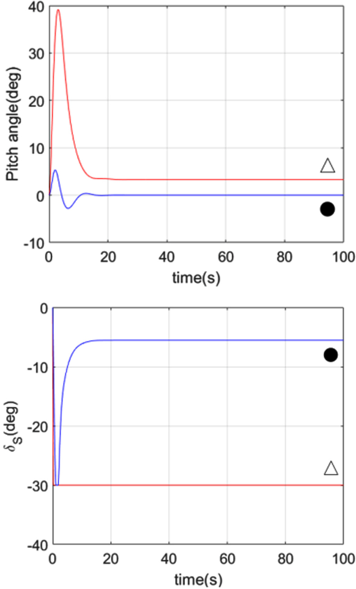
Pitch angles and δS (synchronous elevator angle) under an applied disturbance
5. Conclusions
We determined the feasible regions of the center of gravity and towing point at which the attitude of a towfish with elevators attached to its left and right horizontal tail wings can be controlled using dynamic analyses of the towing point, center of gravity, and elevator capacity. In addition, simulations were performed using the equations of motion of the towfish to verity the feasible regions. It was shown that the attitude is easy to control in some regions and difficult to control in others. At the positions at which the attitude is easily controlled, there is a margin in the elevator angle; thus, even if disturbances are applied, the target attitude is reached quickly. However, at the other positions, there was little margin in the elevator angle; thus, the system could not respond quickly to the effects of disturbances. These locations of the towing point and center of gravity are expected to become an index for determining the towing point, center of gravity, and elevator capacity in the design of towfish and their operation in real seas.
Acknowledgements
Support for this research was provided by the Civil-Military Technology Cooperation Project of the Institute of Civil-Military Technology Cooperation, and the authors would like to express their gratitude for the support (Project Number: 15-CM-SS-01, Project Name: Towing interferometric synthetic aperture sonar (InSAS) development).
References
Article information Continued
Notes
Nomenclature
fc Towed force
fe Elevator force
fb Restoring force and moment
rc Position vector from CG to towing point
re Position vector from CG to center of elevator
fc(xz) Towed force in xz plane
fe(xz) Elevator force in xz plane
rc(xz) Position vector to towing point in xz plane
re(xz) Position vector to center of elevator in xz plane
W Weight
B Buoyant force
δl, δr Left and right elevator angle
δS Synchronous elevator angle
s Area of a single elevator
CD Drag coefficient of elevator
CL Lift coefficient of elevator