Numerical Study on Wave Run-up of a Circular Cylinder with Various Diffraction Parameters and Body Drafts
Article information

Abstract
Wave run-up is an important phenomenon that should be considered in ocean structure design. In this study, the wave run-up of a surface-piercing circular cylinder was calculated in the time domain using the three-dimensional linear and fully nonlinear numerical wave tank (NWT) techniques. The NWT was based on the boundary element method and the mixed Eulerian and Lagrangian method. Stokes second-order waves were applied to evaluate the effect of the nonlinear waves on wave run-up, and an artificial damping zone was adopted to reduce the amount of reflected and re-reflected waves from the sidewall of the NWT. Parametric studies were conducted to determine the effect of wavelength, wave steepness, and the draft of the cylinder on the wave run-up of the cylinder. The maximum wave run-up value occurred at 0°, which was in front of the cylinder, and the minimum value occurred near the circumferential angle of 135°. As the diffraction parameter increased, the wave run-up increased up to 1.7 times the wave height. Furthermore, the wave run-up was 4% higher than the linear wave when the wave steepness was 1/35. In particular, the crest height of the wave run-up increased by 8%.
1. Introduction
Fossil fuel use is steadily increasing due to global energy consumption and economic development. Owing to the depletion of fossil fuels, studies on the development of marine energy resources are being actively conducted (Lee et al., 2013). Accordingly, various marine structures such as wind farms and wave power structures as well as traditional spar or semi-submersible structures have been developed. In recent years, the installation and operation of offshore structures in coastal waters as well as in deep sea and polar conditions have increased. Therefore, studies are being conducted to understand the structural safety and motion performance of marine structures under environmental loads such as extreme waves and winds. Typical research topics include the wave run-up or air-gap due to design wave height, and model tests and numerical analysis techniques are being developed to understand such phenomena (Song and Park, 2017).
Studies on the estimation of wave run-up based on the potential flow theory have been conducted. McCamy and Fuchs (1954) calculated the wave run-up of a bottom fixed single cylinder based on the linear potential theory. Kriebel (1992) conducted a model experiment on a bottom fixed cylinder and confirmed that the wave run-up calculated based on the linear potential theory was lower than the measurement taken in an actual model experiment. Yang and Ertekin (1992) employed a second-order Stokes wave and solitary wave to calculate the external force and wave run-up applied to a cylinder. Lee et al. (2013) estimated wave run-up based on the linear wave theory and compared it to that measured in a model experiment with a two-dimensional wave tank. Li and Liu (2019) proposed an analytical solution by calculating the external force and moment for a surface-piercing cylinder, bottom fixed cylinder, and fully submerged floating cylinder based on the multi-term Galerkin method, and compared the results with the numerical analysis results based on the high-order boundary element method (HOBEM). Oh et al. (2019) conducted a similar study based on the potential flow theory in which they analyzed the hydrodynamic behavior of the body through frequency domain analysis. In addition, a number of numerical studies have been conducted using a three-dimensional numerical wave tank (NWT) based on the potential flow theory. In the three-dimensional NWT, the physical wave tank experiments are numerically simulated through techniques such as the boundary element or finite element methods, which is an analysis technique for nonlinear wave analysis and nonlinear motion analysis. Koo and Kim (2004), Oh et al. (2018), and Wu and Eatock Taylor (1995) have conducted analyses using a two-dimensional nonlinear NWT. In particular, Wu and Eatock Taylor (1995) analyzed the radiation problem with a circular cylinder using the boundary element method and finite element method for a two-dimensional nonlinear NWT. Boo and Kim (1996) solved the diffraction problem using HOBEM for a three-dimensional NWT, and Celebi et al. (1998) analyzed nonlinear environmental loads and wave run-ups of a bottom fixed cylindrical structure and moored floating cylinder in a three-dimensional nonlinear NWT. Bai and Eatock Taylor (2007) solved the diffraction problem of single and concentrated waves by a floating cylinder using the decomposition method for a three-dimensional NWT. Kim and Koo (2019) developed a three-dimensional fully nonlinear potential NWT based on the constant panel method to solve the diffraction, radiation, and vertical motion problems for a wave energy converter.
Various other studies on wave run-up have been conducted. For instance, Li et al. (2012) studied wave run-up between a multi-directional focused wave and cylinder, and Kim et al. (2014) performed numerical analyses of the frequency domain based on the potential flow theory for experiments and a comparison of the characteristics of nonlinear wave run-up around the column of semi-submersible marine structures. In the experiment conducted under light draft and short period conditions, strong nonlinearity was observed at the front of the column, and based on this, it was necessary to consider the nonlinear wave run-up characteristics for semi- submersible marine structures. Recently, with the development of computational fluid dynamics (CFD), many studies have been conducted on wave run-up and wave load. Moon et al. (2018), Liu and Wan (2017), Song and Park (2017), and Fan et al. (2019) conducted a study on the wave run-up of vertical circular cylinders using OpenFOAM. In particular, Fan et al. (2019) studied the effects of wave steepness, relative size of an object, and change in water depth on wave run-up, and confirmed that the size of the wave run-up was significantly influenced by the wave steepness and relative size of the object.
In this study, a wave run-up phenomenon that acts on a cylinder having a circular cross section, which is a typical shape for a marine structure column, was studied using a three dimensional NWT. To this end, the three-dimensional fully nonlinear potential NWT technique developed by Kim and Koo (2019) was used. This technique is an analysis program based on the boundary element and Mixed Eulerian–Lagrangian (MEL) methods, and it is a suitable analysis program for nonlinear wave and wave-floating body interaction analysis. Based on this analysis technique, the wave run-ups were compared at all circumferential angles of the circular cylinder to compare the locations where the maximum and minimum values were formed. In addition, the effect of the diameter (D) and draft (d) of the cylinder at various wavelengths on the wave run-up was studied by analyzing the incident waves of various periods. The effect of wave nonlinearity on the wave run-up at various wave steepness values was studied by comparing changes in the wave run-up under various wave steepness conditions.
2. Problem Formulation
In order to calculate the wave run-up occurring on the cylinder surface, it is assumed that the computational domain is a non-viscous, incompressible, non-rotating potential fluid. Based on this, the velocity potential(ϕ) is introduced, and the governing equation becomes the Laplace equation as in Eq. (1).
To calculate the wave run-up occurring on the surface of a cylinder, it is assumed that the fluid in the computational domain is a non-viscous, incompressible, and non-rotating potential fluid. Therefore, when the velocity potential (ϕ) is introduced, the governing equation becomes the Laplace equation, which is shown below:
In addition, the Laplace equation can be converted to a boundary integral equation by Green's second identity:
Free surface boundary conditions can be divided into kinematic and dynamic conditions, and the linear free surface boundary conditions can be expressed by Eqs. (3)–(4).
The semi-Lagrangian approach (v⃗ = (0,0, δη/δt) is applied to the nonlinear free surface boundary conditions, which can be expressed by Eqs. (5)–(6), to consider the effects of nonlinear waves.
where η denotes the displacement of the free surface. As the boundary condition of the incident wave, a progressive wave is generated by substituting the incident wave component in the left end of the computational domain. The linear wave is applied as the incident wave for linear analysis, and the second-order Stokes wave is applied in the nonlinear analysis. Eq. (7) shows the boundary condition of the incident wave according to the second-order Stokes wave that is applied in the analysis of the nonlinear wave. In the case where the incident wave is linear, only the first term of Eq. (7) was applied for the boundary condition.
In addition, the boundary surface of the circular cylinder and side wall surface of the numerical wave tank are applied as a rigid interface (∂ϕ/∂n = 0), and the bottom surface is expressed using the image method. Fig. 1 shows the overall computational domain used to determine wave run-up around the cylinder. To create an open sea condition while eliminating the unnecessary reflected waves that may be generated on the free surface, an artificial damping zone is applied in the frontal, side, and end damping zones, and the length of each damping zone is set to one wavelength (1λ). Moreover, the analysis domain is represented by x-axis symmetry to shorten the analysis time by reducing the number of computational elements. The least square technique is employed for reconstructing the gradient for spatial differentiation, and the inverse distance weighting (IDW) method is employed for interpolation of the nodes. Further details can be found in Kim and Koo (2019).
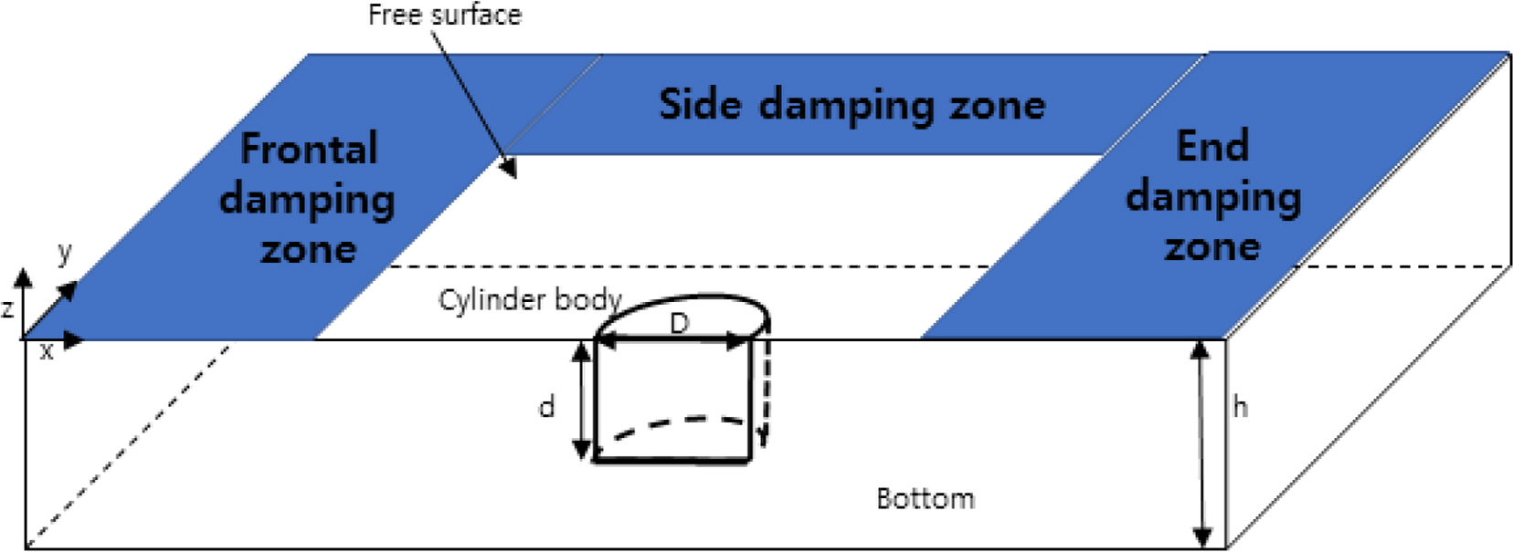
Overview of computational domain
3. Numerical Analysis Model and Results
3.1 Numerical Analysis Model and Analysis Conditions
In this study, numerical analysis was performed on a surface-piercing cylinder protruding from a free surface. Fig. 1 shows an overview of the computational domain. Fig. 2 shows the positions of the wave gauges for measuring the wave run-up on the free surface. Each wave gauge was placed at an interval of 22.5°. Table 1 shows the dimensions and specifications of the numerical analysis models. As shown in Table 1, the analysis was performed by increasing the draft (d) from 1.5 m to 9 m while maintaining the diameter (D) at 3 m. Fig. 3 shows the appearance of the panel (mesh) in the numerical analysis model. The number of elements in the numerical analysis model is 250 at d = 1.5 m; 350 at d = 3 m; 450 at d = 4.5 m; 550 at d = 6 m; and 750 at d = 9 m. Table 2 shows the 13 incident wave conditions that were calculated for linear and nonlinear analyses. First, the effect of the diffraction parameter was examined by changing D/λ from a minimum of 0.1203 to a maximum of 0.4360, and analysis was performed with varying wave steepness from 0.006 to 0.03 under the condition of a specific diffraction parameter. The water depth was fixed at 15 m.
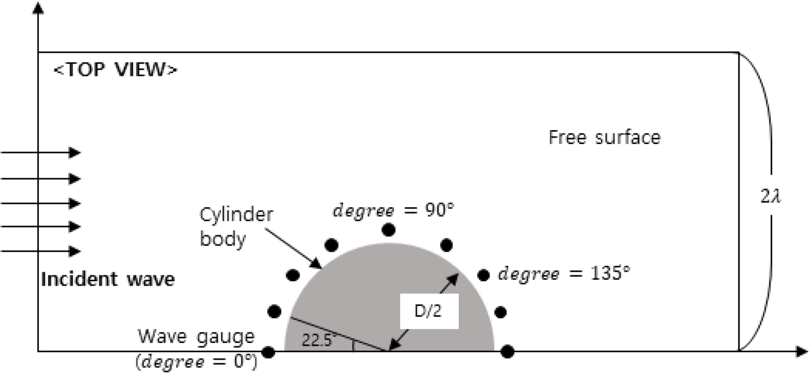
Top view of the computational domain
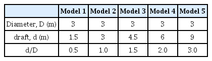
Principal dimensions of the cylinder models
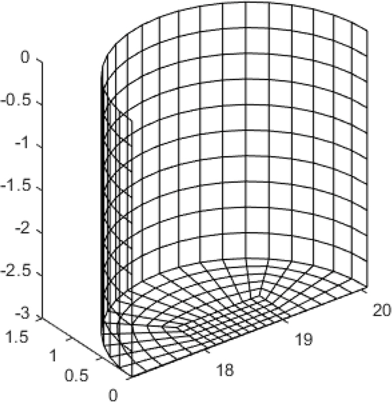
Meshes of the circular vertical cylinder

Incident wave conditions
3.2 Wave Run-up Analysis Using a Three-dimensional Linear NWT
To verify the wave run-up of the NWT, wave run-ups at various angles of the cylinder were compared with the numerical analysis results of Lee et al. (2013), as shown in Fig. 4. The specifications of the numerical analysis model were D = 16 m, d = 24 m, and h = 60 m. The incident wave height was fixed at 0.3 m, and the wave run-up height (R) was calculated by averaging time series results in which the steady state lasted for five cycles after the incident wave reached the cylinder. Fig. 4 shows that the results of the numerical analysis of this study agree well the results of Lee et al. (2013) for all circumferential angles.
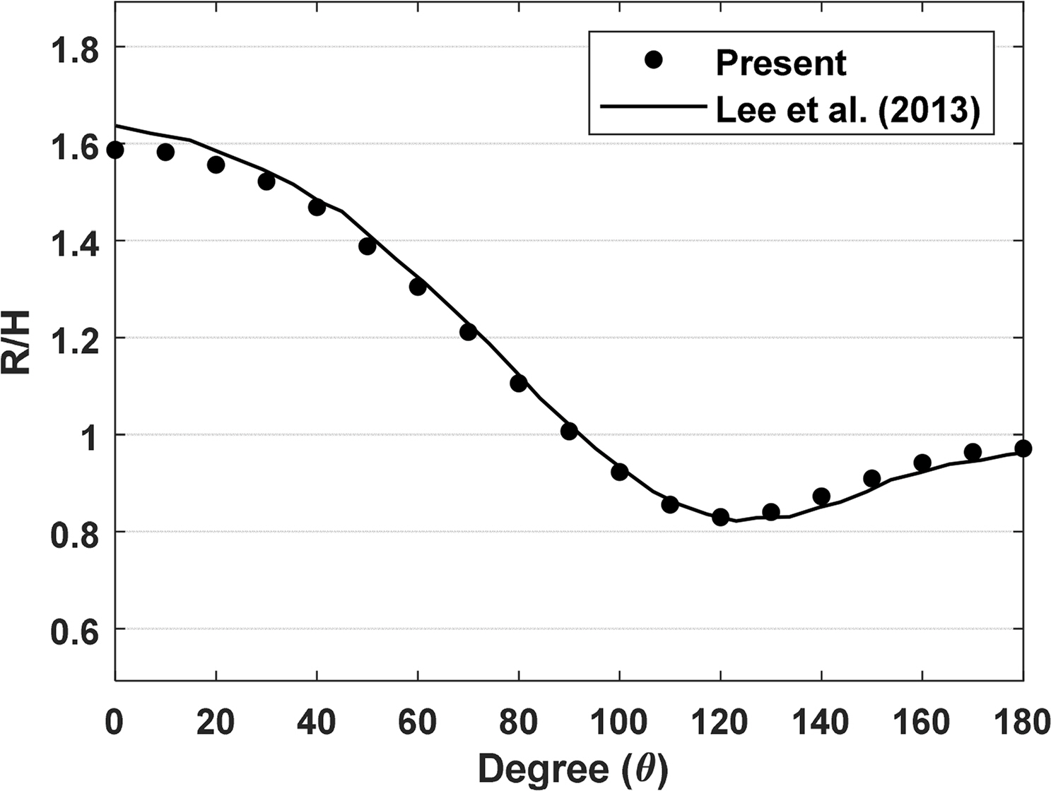
Comparison of the wave run-up obtained in the present study and that obtained by Lee et al. (2013) (T= 7.0 s, h = 60 m)
Based on the developed NWT, the effects of the diffraction parameter (D/λ) and cylinder draft (d) on the wave run-up were determined. Fig. 5 shows a comparison of the wave run-ups for various diffraction parameters and the representative circumferential angles, which were set to 0°, where wave run-up was at its maximum as shown in Fig. 4; 135°, where wave run-up was at its minimum; and 90°, which was the central point of the cylinder. The draft and the diameter of the cylinder were set to 3 m each. As the diffraction parameter increased, wave run-up decreased when the circumferential angle was 135°, but it gradually increased at 0° and 90°. In particular, at 0°, where the wave run-up reached its maximum value, it converged to approximately 1.7 times the incident wave height as the diffraction parameter increased. An increased diffraction parameter indicates that the incident wavelength is relatively small compared to the cylinder diameter, and a considerable portion of the incident wave is reflected from the front of the cylinder. If total reflection occurs, such as under completely blocked conditions, which could be achieved with a sea wall, a standing wave is generated, and the maximum wave run-up that can be measured is twice the incident wave height.
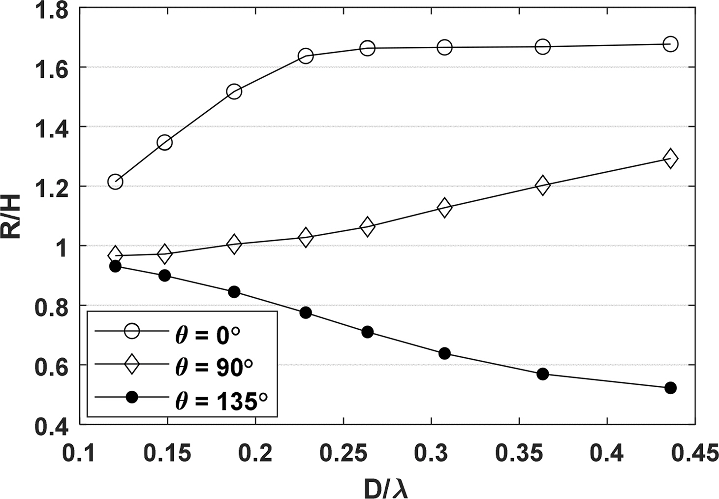
Comparison of wave run-ups for various diffraction parameters and measurement points (d= 3 m, D = 3 m)
This study confirmed that wave-run up was at maximum at approximately 1.7 times the incident wave height owing to the shape characteristics of the circular cylinder. If this analysis is applied to an actual design, it can be expected that the free-board of a structure should be at least 1.7 times the incident wave height under the head sea condition, where the incident wave enters (circular angle 0°), to secure the air gap without affecting the topside of a fixed structure. Fig. 6 compares the wave run-up for various angular and diffraction conditions. As the diffraction parameter decreases, the difference in wave run-up decreases, and R/H gradually approaches 1. This is considered to be due to the decreased diffraction effect of the incident wave caused by the cylinder as the diffraction parameter falls below 0.2. Conversely, as the diffraction parameter increases, the difference in wave run-up according to the circumferential angle increases. In particular, when the diffraction parameter is the highest at 0.3634, wave run-up of approximately 1.6 times the wave height occurs around the circumferential angle of 0° to 50°. At a circumferential angle of 90° or greater, the wave run-up is generally reduced, and only approximately 0.6 times the incident wave height at 135°.

Wave run-up at all circumferential angles for various D/λ (d = 3 m, h= 15 m)
Fig. 7 compares the wave run-up at measurement point (a) with a circumferential angle of 0° and measurement point (b) with a circumferential angle of 135° for cylinders with various draft conditions, where the maximum and minimum wave run-ups occur, respectively. As shown in Fig. 7(a), as the draft of the circular cylinder increases, the wave run-up at the measurement point where the circumferential angle was 0° generally increases. However, this trend decreases as the draft increases, and as the diffraction parameter increases, the increase decreases. When the diffraction parameter is small (D/λ < 0.2), the maximum wave run-up difference according to the draft is approximately 26%, and when the diffraction parameter is large (D/λ > 0.25), the maximum difference is approximately 7.4%. When the draft is small compared to the cylinder diameter (0.5 times), the wave run-up is considerably smaller than under other cylinder conditions with a small diffraction parameter. It appears that the incident wave does not affect the cylinder owing to the low draft, and most of it passes through. As shown in Fig. 5, the wave run-up increases and converges to 1.7 as the diffraction parameter increases. Based on this, it can be confirmed that the free-board of the cylindrical structure should be at least 1.7 times the incident wave height regardless of the cylinder draft.

Wave run-up under various d/D conditions for two different circumferential angles (a: angle = 0°and b: angle = 135°)
Fig. 7(b) shows the variation in the wave run-up with the ratio of the draft and diameter of the cylinder at the circumferential angle of 135°, where the wave-run up is at its lowest. The wave run-up decreases under all draft conditions as the diffraction parameter increases. Furthermore, when the draft is greater than or equal to the cylinder diameter (d/D ≥ 1), a similar wave run-up is generated irrespective of the value of the draft.
Fig. 8 compares the horizontal and vertical forces of a circular cylinder under various draft conditions. All vertical forces were nondimensionalized with F/ρgA(D/2)d, where A denotes the amplitude of the incident wave. As the cylinder draft increases and the diffraction parameter decreases, the horizontal force generally increases, which is due to the relatively long wavelength of the incident wave increasing the area where the wave energy acts on the cylinder. This relationship between the wavelength and cylinder draft can be observed more prominently by comparing the horizontal force when the diffraction parameter is large. When the diffraction parameter increases, the incident wavelength becomes relatively small, and its effect on the lower surface of the water plane of the circular cylinder is reduced. Because of this, the horizontal force remains almost similar for a deep draft cylinder. In Fig. 8(b), it can be seen that the vertical forces decrease unlike the horizontal forces. The vertical force decreases as the diffraction parameter increases, that is, as the wavelength is relatively reduced. This is because the effect of the wave on the bottom surface of the cylinder, based on which the vertical force is calculated, is reduced.
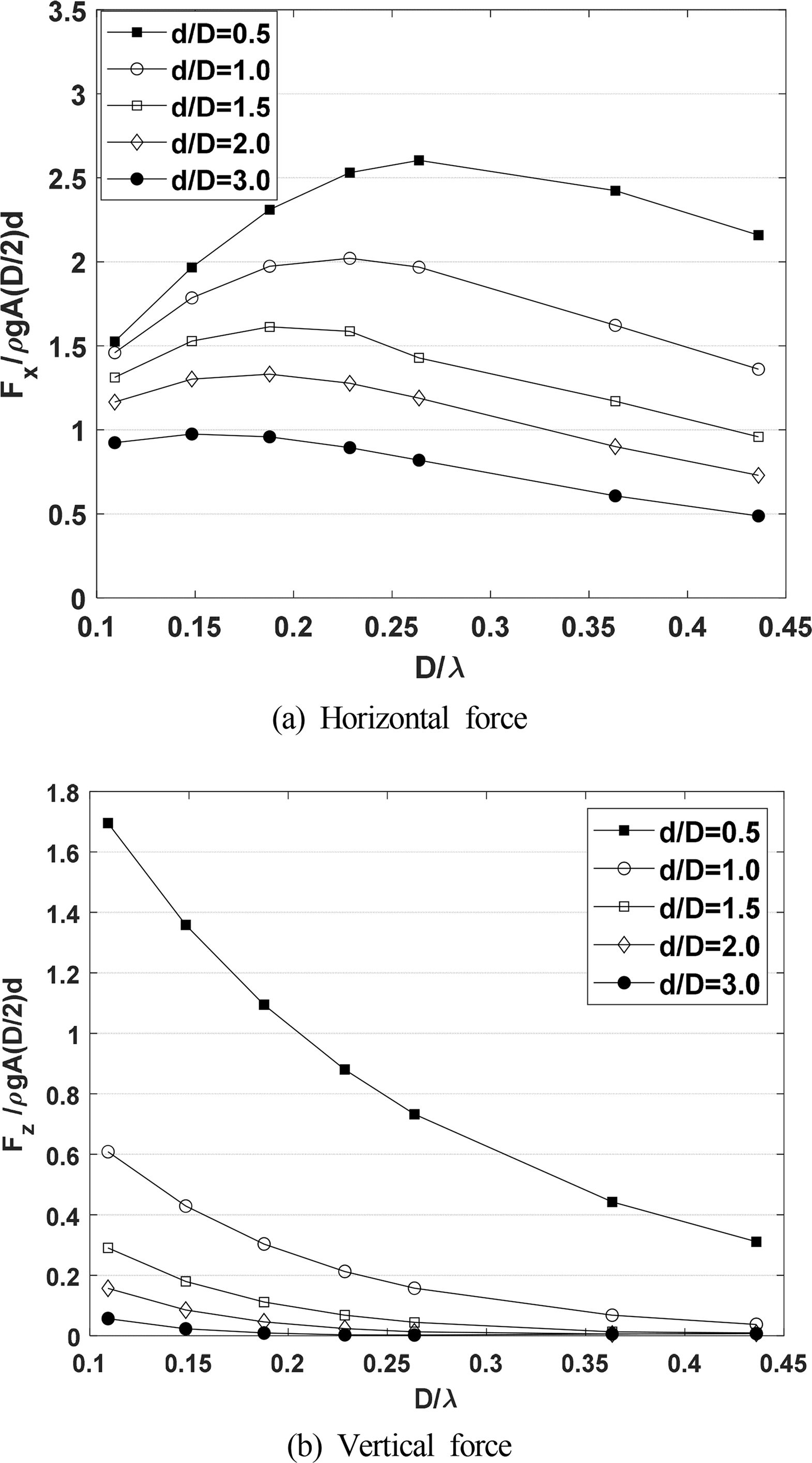
Comparison of (a) horizontal forces and (b) vertical forces under various draft conditions
3.3 Wave Run-up Analysis Using a Full Nonlinear NWT
The variation in the wave run-up of the cylinder because of the nonlinear effect of the incident wave was investigated using a full nonlinear NWT. Unlike linear NWT, which uses linear free surface conditions and incident wave conditions that do not show the variations in the wave run-up due to variations in the wave height, the nonlinear analysis using the nonlinear free water surface boundary conditions can reveal the effect of wave steepness on wave run-up.
Fig. 9 compares the time series data of the wave run-up for the linear and nonlinear analyses for two wave steepness conditions. The wave steepness (H/λ) values were selected as 1/150 and 1/35 for the linear and relatively large nonlinear effects, respectively. All results used were from the period when t/T was between 6 and 11, during which the time series data reached a steady state. When the wave steepness of a typical nonlinear wave (Stokes wave) condition (1/35) is applied, the crest height of the wave run-up increases by 8% and the trough height decreases by 6% compared to the linear analysis results. When the wave steepness is 1/150, it is almost identical to the time series obtained by the linear NWT, which confirms that the nonlinear effect occurs as the wave steepness increases.

Time histories of the wave run-up for different wave steepness values (d/D = 1.0, D/λ = 0.3634, and angle = 0°)
Fig. 10(a) and 10(b) show snapshots of the free water surface area around the cylinder of the NWT for the maximum and minimum diffraction parameters of 0.3634 and 0.1203, respectively, for a wave steepness of 1/35. Fig. 10(a) shows a more pronounced wave run-up. Moreover, this visually confirms that the wave run-up is small in general when the cylinder circumferential angle is 90° or greater.
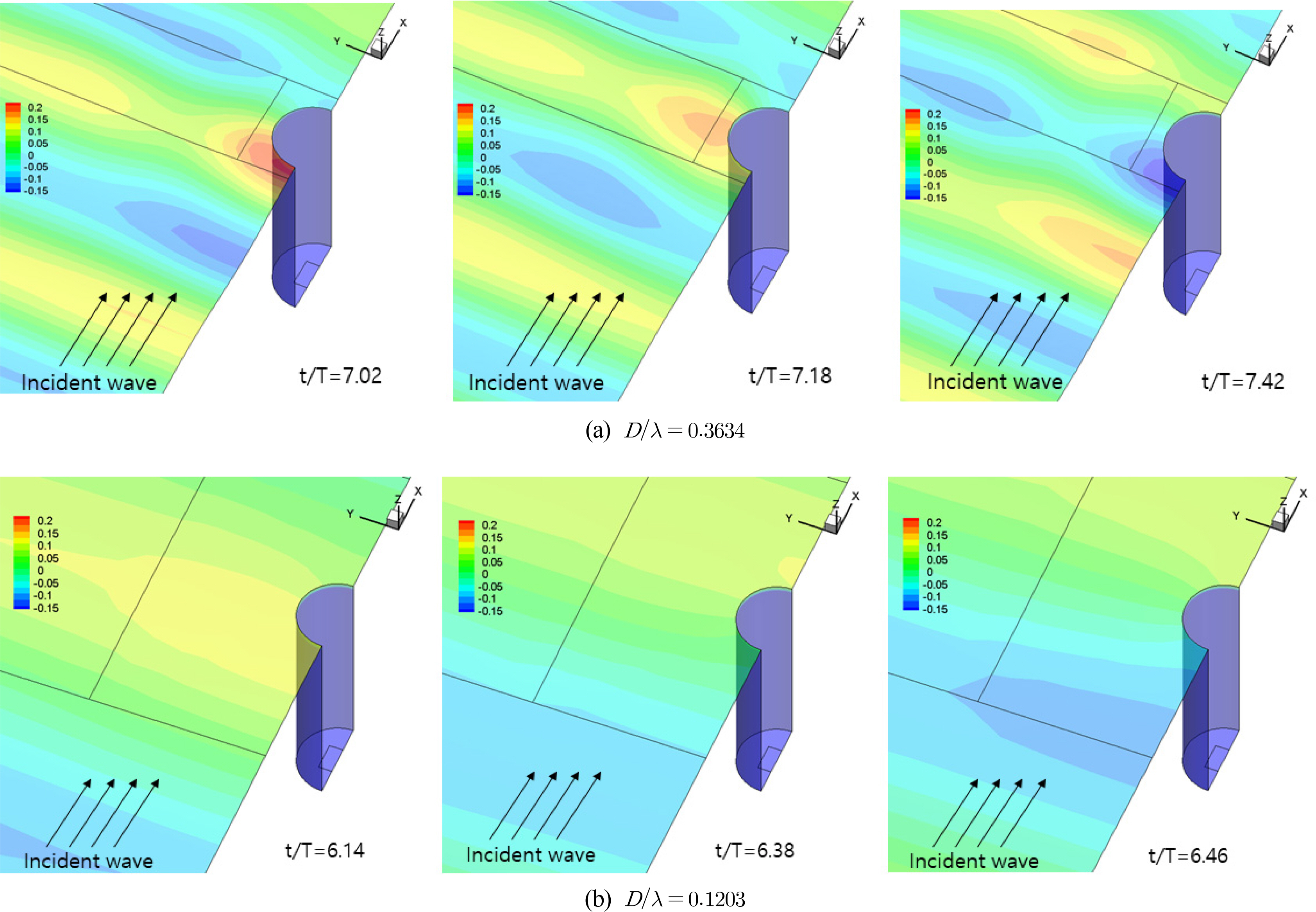
Snapshot results of numerical wave tank calculations for two different diffraction parameters (d = 9.0 m, H/λ = 1/35)
Figs. 11(a) and 11(b) show the variations in the wave run-up with changes in the draft and wave steepness (H/λ) of each cylinder at a cylinder circumferential angle of 0°, where the wave run-up is at its maximum in the linear analysis, and 135°, where the wave run-up is at its minimum. The diffraction parameter (D/λ) was fixed at 0.3634. The wave run-up increases as the wave steepness increases in all cylinders irrespective of the cylinder draft. For 0°, the relative increase rate of the wave run-up increases when the wave steepness is 0.02 or more. As the linear and nonlinear waves are usually demarcated at the wave steepness of 0.02, it can be understood that a larger crest height occurs in the nonlinear wave section, resulting in a greater wave run-up. At 135°, the measuring point with the minimum wave run-up, a relatively high wave run-up occurs when the ratio of the draft and diameter is the smallest (d/D = 0.5). As the light draft allows the incident wave to easily pass through the lower part of the cylinder, a relatively small wave run-up occurs at 0° (Fig. 7 (a)), and a relatively large run-up occurs at 135°.

Wave run-ups for various wave steepness values: (a) Angle = 0°; (b) Angle = 135°
To clearly determine the effect of the ratio of the cylinder draft to the radius on changes in wave run-up, the wave run-ups for d/D of 3.0 measured at 0° for the maximum wave steepness of 1/35 and minimum wave steepness of 1/150 were separated for each frequency component (Fast Fourier Transform applied), as shown in Table 3. A comparison of the frequency components for various wave steepness values reveals that the primary wave frequency components of the wave run-up remain the same as the wave run-up values irrespective of the wave steepness. As the wave steepness increases, the mean value and double frequency components of the wave run-up that are proportional to the square of the wave amplitude and triple frequency components of the wave run-up that are proportional to the cube of the wave amplitude increase. The wave run-up increases by 4% when the wave steepness is approximately 1/35. In particular, when the wave steepness is 1/35, the mean value of the wave run-up (zero order frequency components) is 5% of the primary frequency components and 3% for the secondary frequency components.

Frequency components of the wave run-up (d/D = 3.0, Angle = 0°, H/λ = 1/35, 1/50)
4. Conclusion
In this study, the wave run-up of a circular cylinder was calculated in the time domain using three-dimensional linear and fully nonlinear NWT techniques. The change in the wave run-up was compared and analyzed based on changes in the diffraction parameter (D/λ), which is the ratio of the diameter of the cylinder to the incident wavelength, the circumferential position (angle) of the cylinder, and the change in cylinder draft. In addition, the effect of wave nonlinearity on the wave run-up under various wave steepness conditions was investigated using a nonlinear NWT.
The three-dimensional NWTs used linear and nonlinear free water surface boundary conditions; furthermore, the least square technique and IDW method were applied for gradient reconstruction and spatial differentiation, respectively.
The wave run-up had a maximum value at 0°, in front of the cylinder where the incident wave reached, and a minimum value occurred at approximately 135°. The wave run-up gradually increased as the diffraction parameter increased, but it converged to approximately 1.7 times the wave height irrespective of the draft when D/λ was 0.25 or greater. Based on this, the free-board of a fixed structure composed of a cylindrical lower body should be at least 1.7 times the incident wave height.
The wave run-up, for nonlinear waves with increasing incident wave height increased as the wave steepness increased irrespective of the cylinder draft. The crest height of the wave run-up increased by as much as 8% when the wave steepness was 1/35 compared to when the wave steepness of 1/150. At 0°, where the maximum wave run-up was achieved, the relative increase rate of the wave run-up increased when the wave steepness is 0.02 or greater.
Acknowledgements
This research was supported by the MOTIE (Ministry of Trade, Industry, and Energy) in Korea, under the Fostering Global Talents for Innovative Growth Program (P0008750) supervised by the Korea Institute for Advancement of Technology (KIAT)
This research was funded and conducted under 「the Competency Development Program for Industry Specialists」 of the Korean Ministry of Trade, Industry and Energy (MOTIE), operated by Korean Institute for Advancement of Technology (KIAT). (No. N0001287, HRD program for Korea-UK Global Engineer Education Program for Offshore Plant)