2.3 Simplified Model for Evaluation of Heading Angle Control Performance
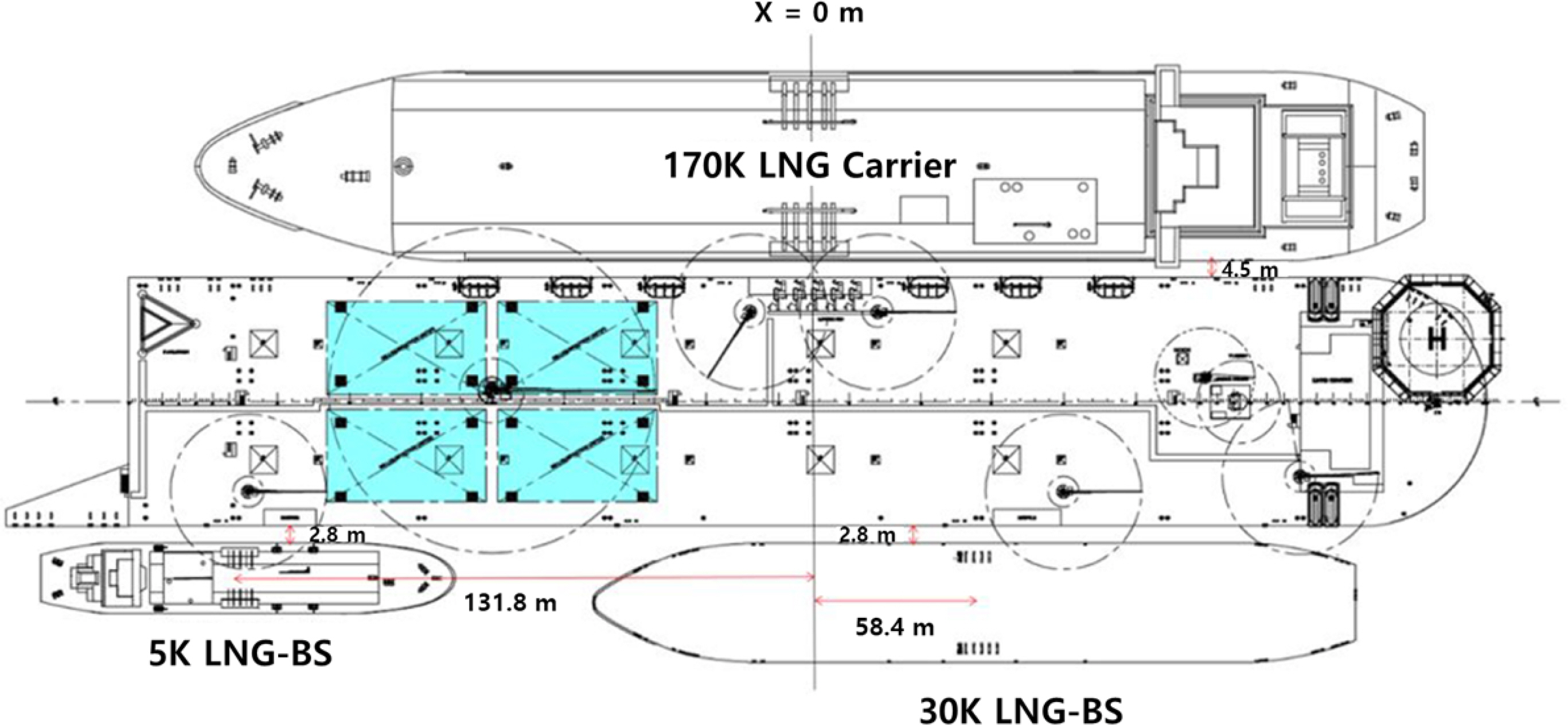
The vessels under test in the LNG loading and off-loading scenarios are a 170K LNG carrier, 30K LNG-BS, and 5K LNG-BS including the FLBT. The principal dimensions of these vessels are shown in
Table 2.
As shown in
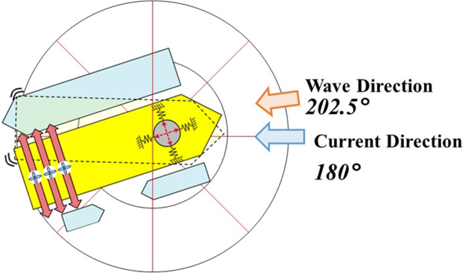
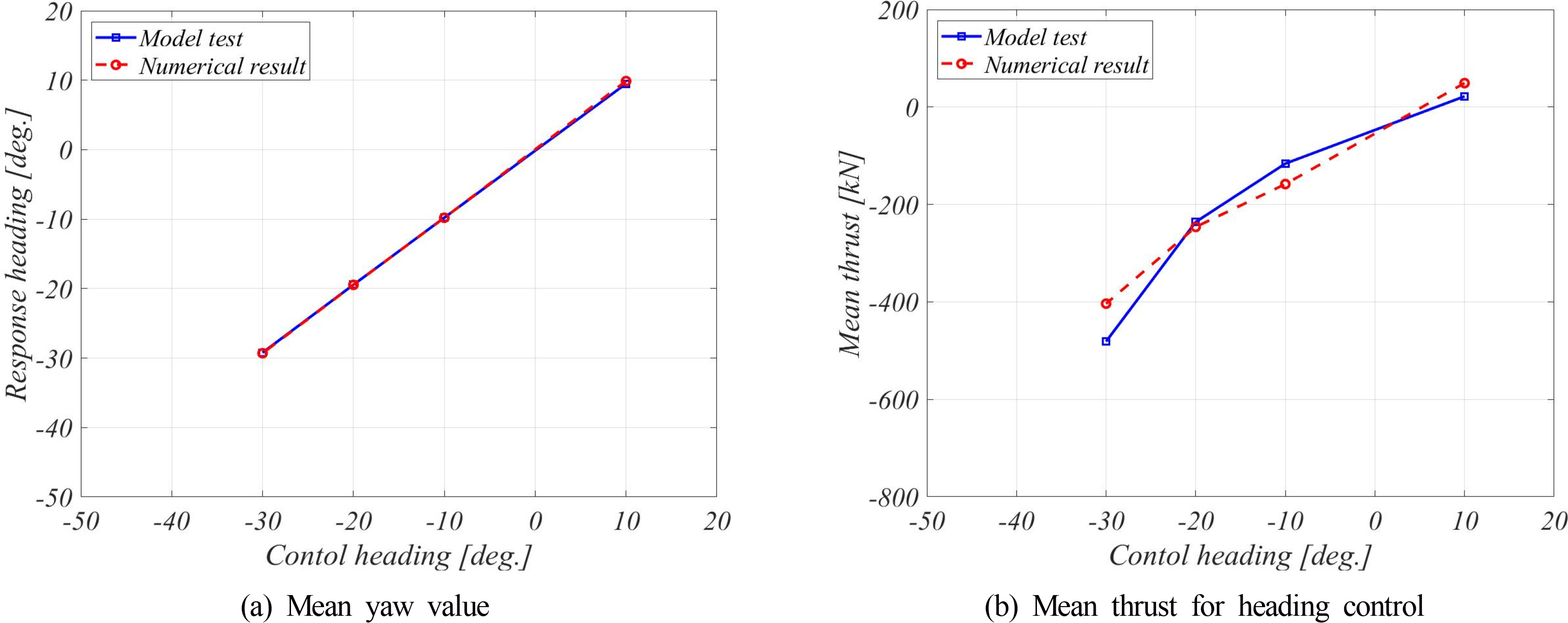
Fig. 4, the FLBT is moored through the heading turret to maintain its position, and three tunnel thrusters are installed at the stern for the heading angle control, which is advantageous for berthing, loading, and off-loading. Each thruster is designed through advanced static analysis and has a capacity of 561 kN (
Oh et al., 2019).
The FLBT is designed to maintain its position by using 15 mooring lines connected to the turret. Five mooring lines form a cluster and the angle between clusters is 120°. In this study, the mooring system was simplified to a simple tensile model as shown in
Fig. 5. As three simple elongation springs are attached to the center of the turret, the turret is modeled in the simulation to have free rotation without a resistance force against rotation. This simplification process is considered suitable for accomplishing the objective of this study i.e., to understand the characteristics of the heading angle of the FLBT. In the modeling, the modeled spring constant was similar to that of the recovery curve of the mooring system (
Oh et al., 2019).
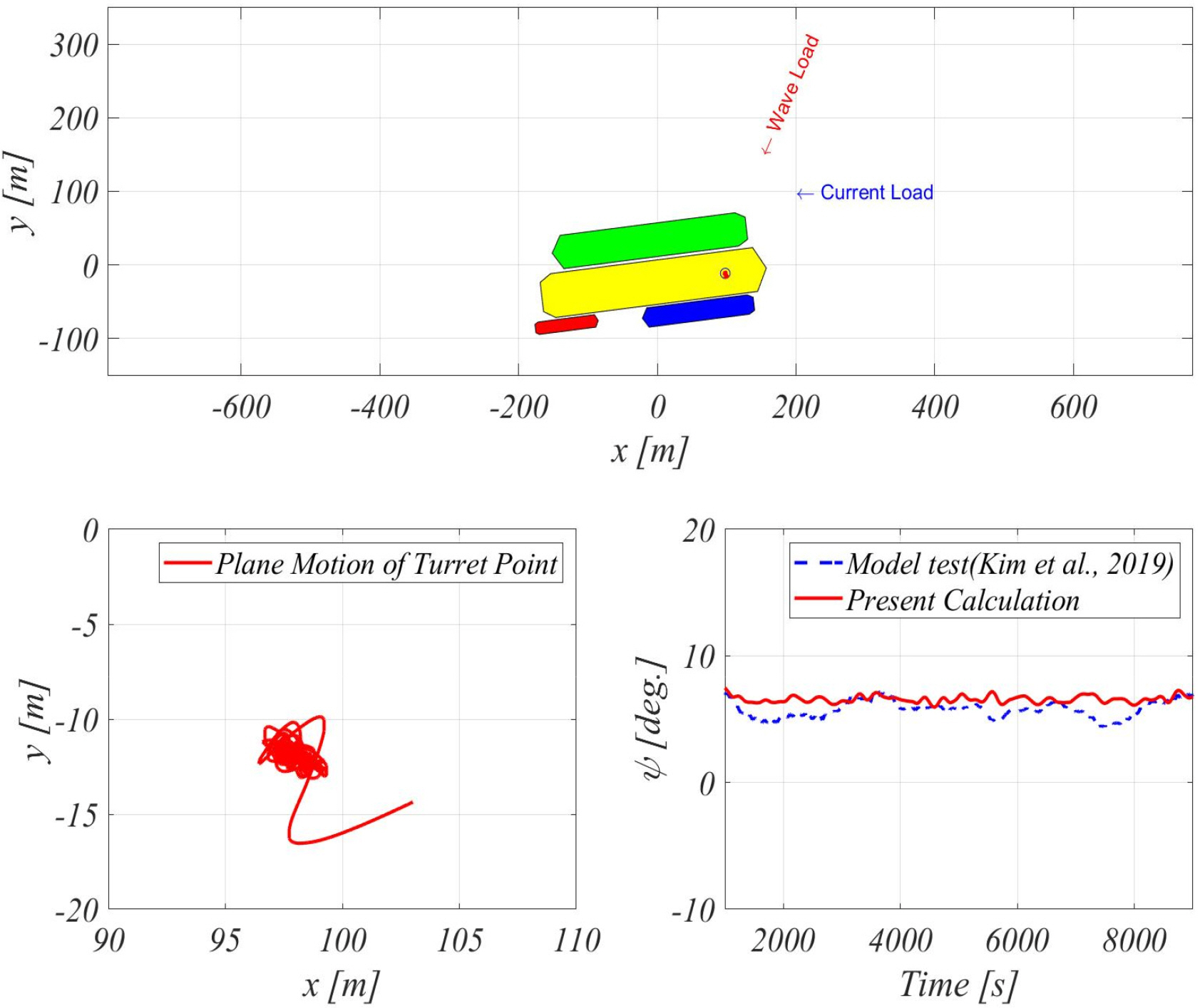
An LNG carrier, 30K LNG-BS, and 5K LNG-BS are deployed in relative positions, as shown in
Table 3, via taut mooring on the FLBT, as shown in
Fig. 1.
In this study, it was assumed that the vessel, which was moored on the FLBT, does not show any relative motion in the heading angle control. According to the previously conducted review studies on loading and off-loading performances (
Kim et al., 2017;
Kim et al., 2018;
Jung et al., 2018;
Jung, 2019), this assumption is reasonable because the maximum relative motion of the vessel was 3.27 m and most relative motions were 1.5 m or smaller. As it was assumed that there is no relative motion between floating bodies, four vessels can be simplified into one rigid body. For simplicity, the load and inertia acting on each floating body are replaced by the FLBT single-hull loading.
The mass and moment of inertia can be simply substituted with
Eqs. (1)–
(2).
where
Mtotal,
MFLBT,
M170K,
M30K and
M5K indicate the substituted mass, and the masses of the FLBT, 170K LNG carrier, 30K LNG-BS, and 5K LNG-BS, respectively.
Izz,total,
Izz,FLBT,
Izz,170K,
Izz,30K and
Izz,5K indicate the substituted yawing moment of inertia, and the yawing moments of inertia of the FLBT, 170K LNG carrier, 30K LNG-BS, and 5K LNG-BS calculated at each center of gravity, respectively.
rFLBT,
r170K,
r30K, and
r5K indicate the distances from the single center of gravity of all the four floating bodies to the center of gravity of the corresponding floating body.
The added mass should also be replaced with a part of the hull of the FLBT. As the heading angle simulation simulates the long-period motion, the added mass at zero frequency was calculated and used. If the frequency is assumed to be zero, then the free surface boundary condition for horizontal motion becomes a rigid wall condition. Therefore, it is defined as a double body problem. The boundary element method was used to solve the boundary value for the double body problem. This method uses the basic solution,
G(
x⃗,
ξ⃗),, which is represented by
Eq. (3), and the boundary integral in
Eq. (4).
where
where
x⃗ and
ξ⃗ are the field and source points, respectively, and the density function,
σ(
ξ⃗), is an unknown value determined only by the boundary conditions. The density function,
σ, can be determined through a system of equations derived from the boundary conditions of an object. The surface potential of the object,
ϕ, can be calculated using the determined density function,
σ, and
Eq. (4). The calculated mass,
aij, can be obtained by substituting the calculated potential,
ϕ, into
Eq. (5).
where
ρ is the seawater density and
nj(
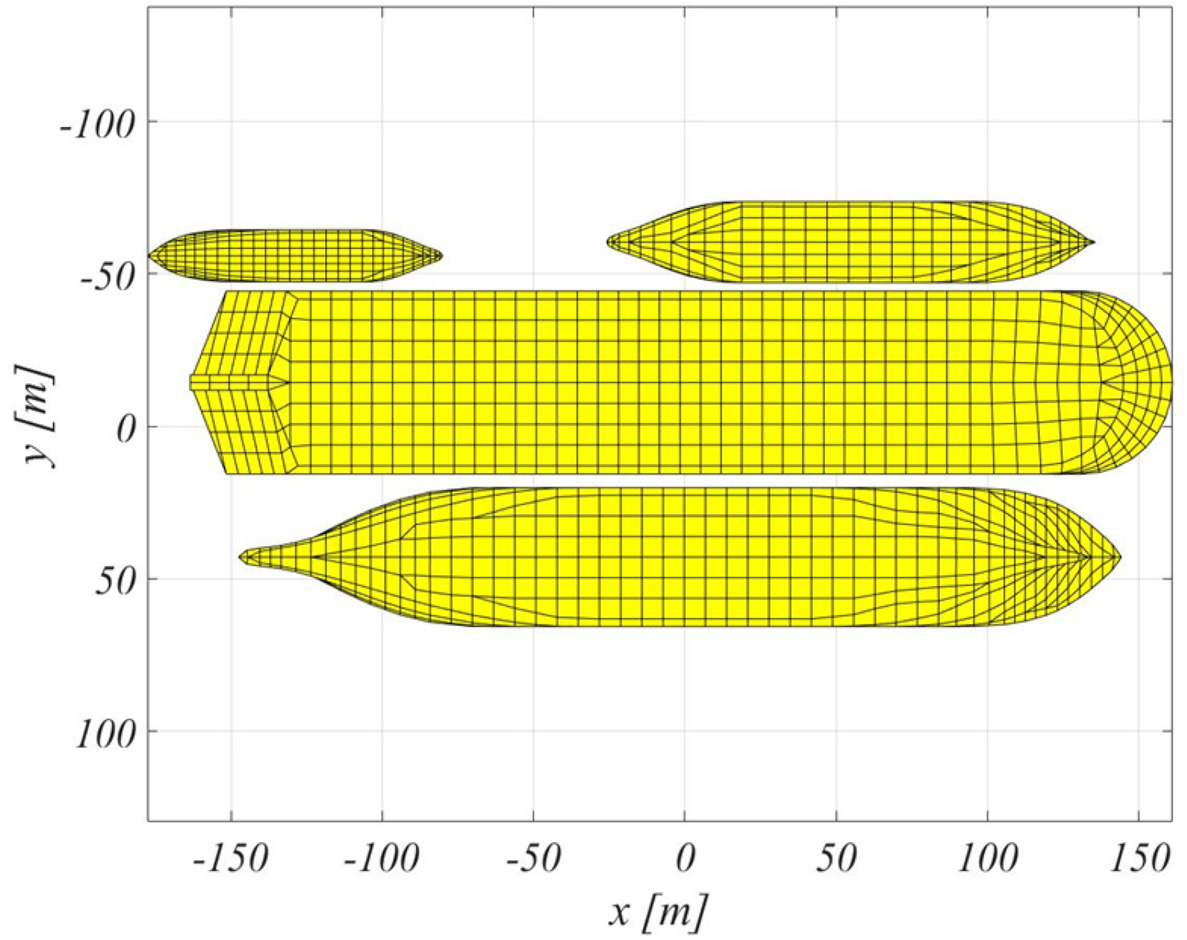
j = 1,2,6) represents the normal vectors of the body surface. The panel mesh applied to the calculation is shown in
Fig. 6 and the displacement error was within 0.065% in the modeling. The calculated added mass is summarized in
Table 4.
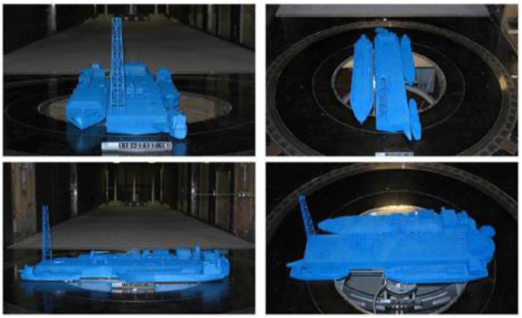
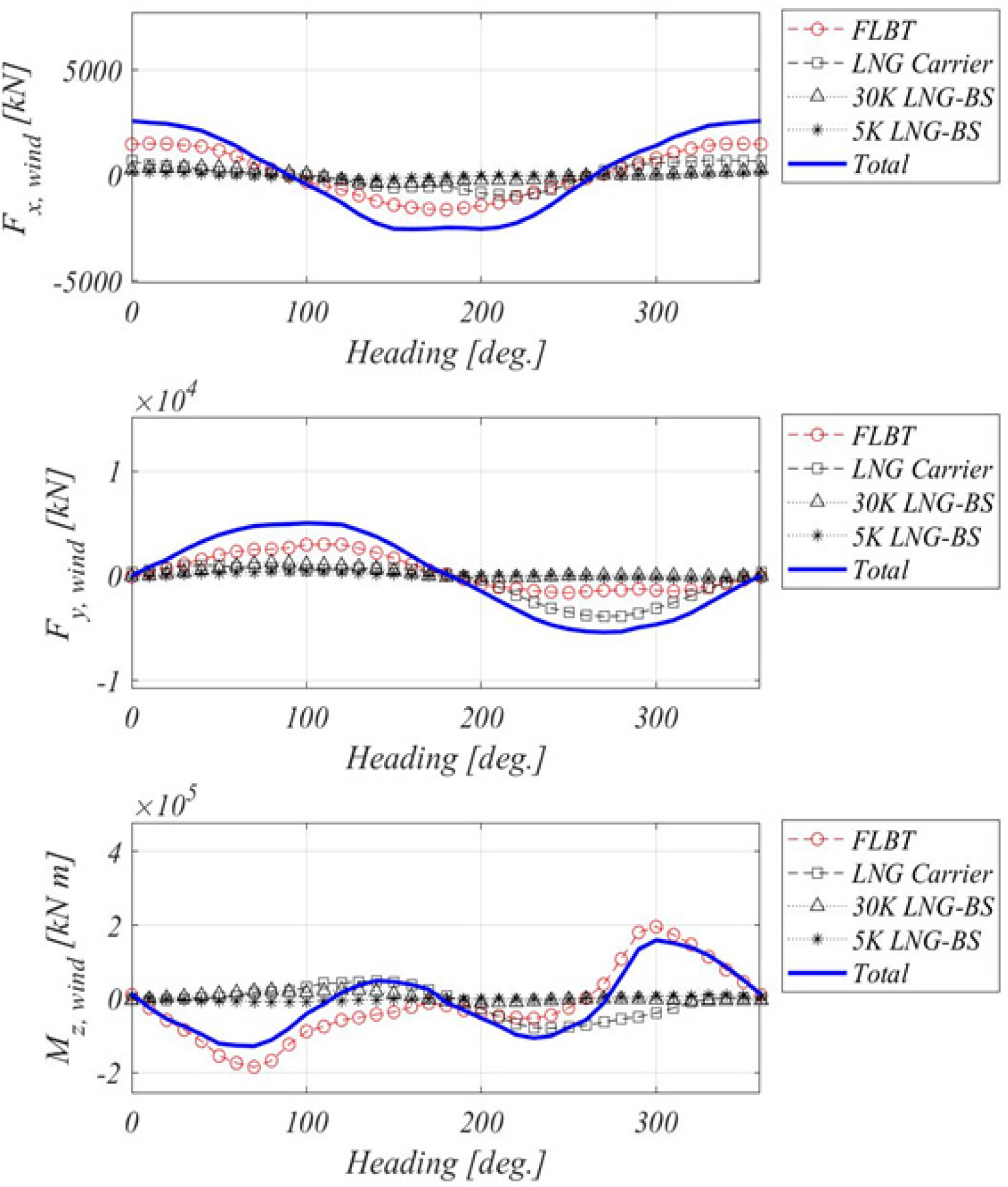
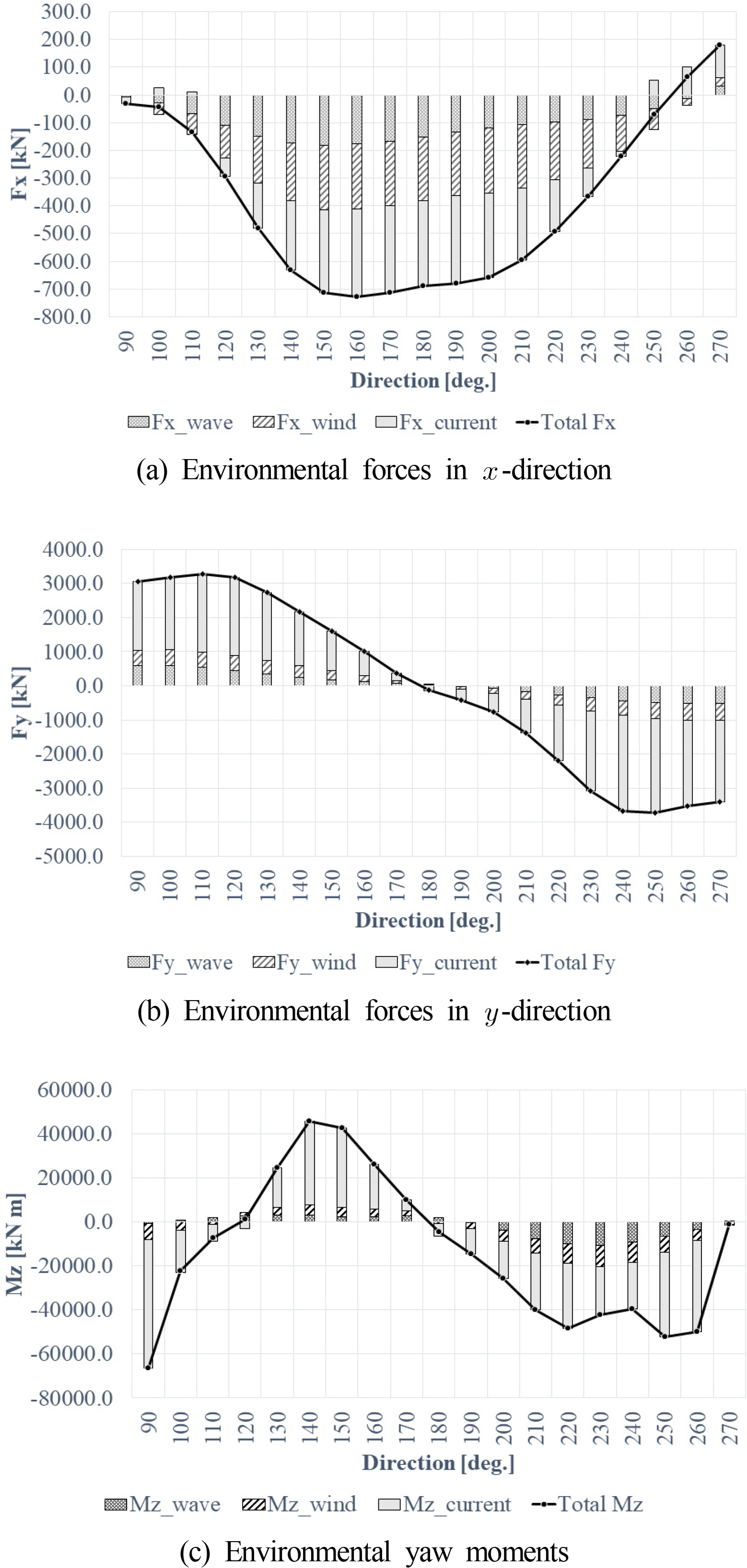
The load acting on each floating body was composed of wind load, current load, and wave drift load. For the wind load, the result of the wind tunnel test conducted in the study by Park et al
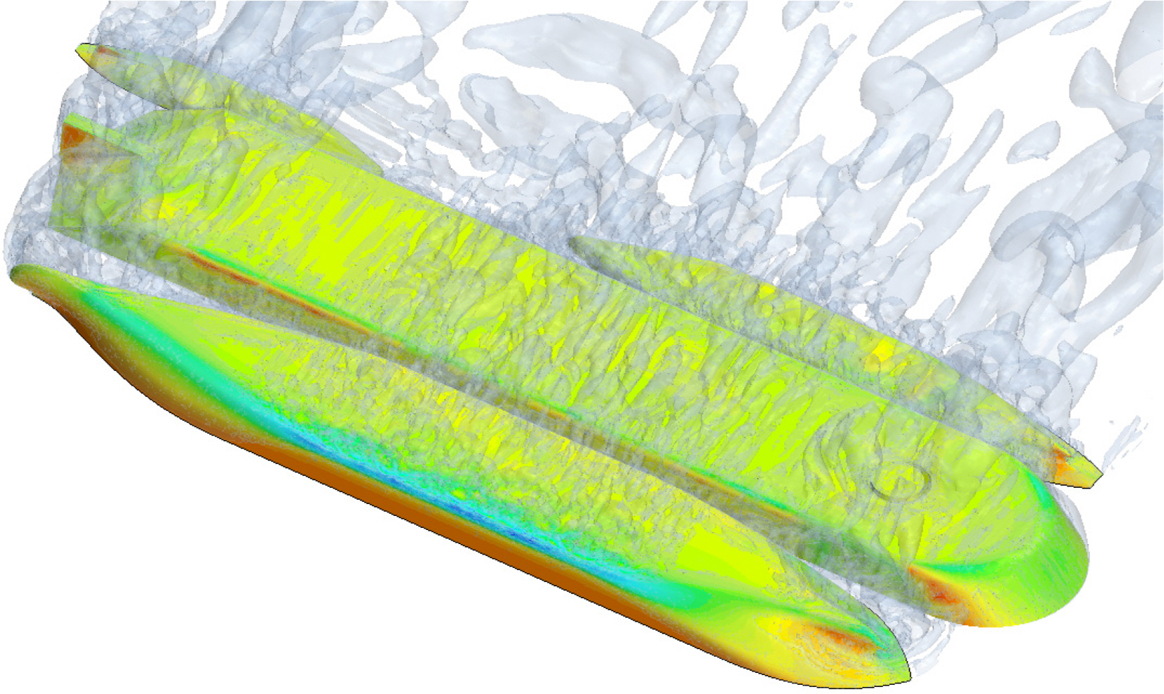
. (2017) was used. The wind tunnel test was conducted in Force Technology in Denmark, as shown in
Fig. 7. The model ship was made of high-density polyurethane foam and was used for the test by separating the top part of the ship under test from the repair surface and below.
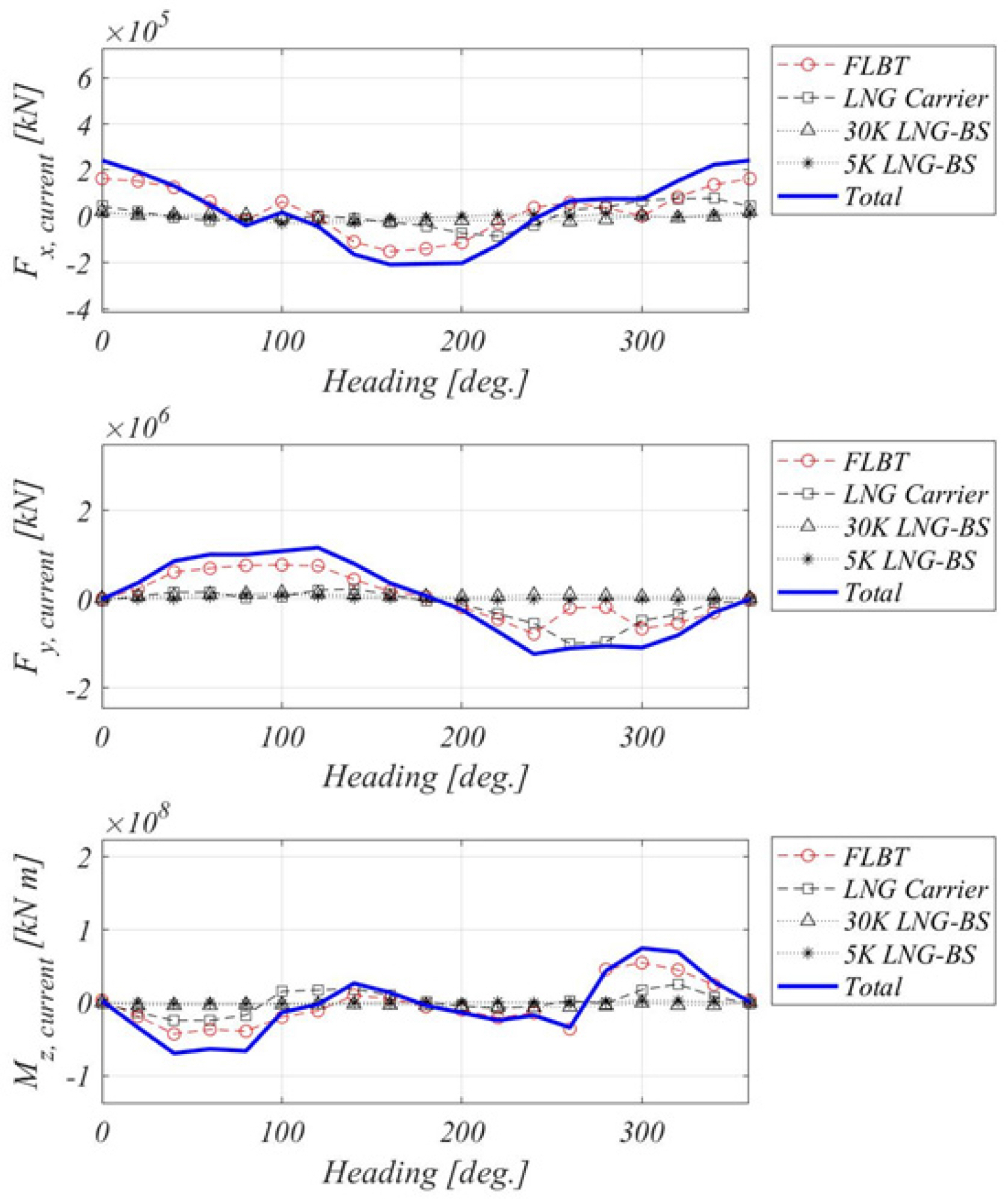
The current load was calculated based on the study conducted by
Jung et al. (2017), in which computational fluid dynamics calculations were performed and the current load coefficient was calculated. Based on the computational analysis, which was systematically performed by
Jung et al. (2017), the current load coefficient was measured in the wind tunnel test, and it was confirmed that the coefficient was affected by the experimental environment of the wind tunnel. Furthermore, the analysis indicated that Boundary conditions for unbounded flow were not satisfied. Based on the study by
Jung et al. (2017), the docked current loads of four floating bodies were calculated in this study as shown in
Fig. 8.
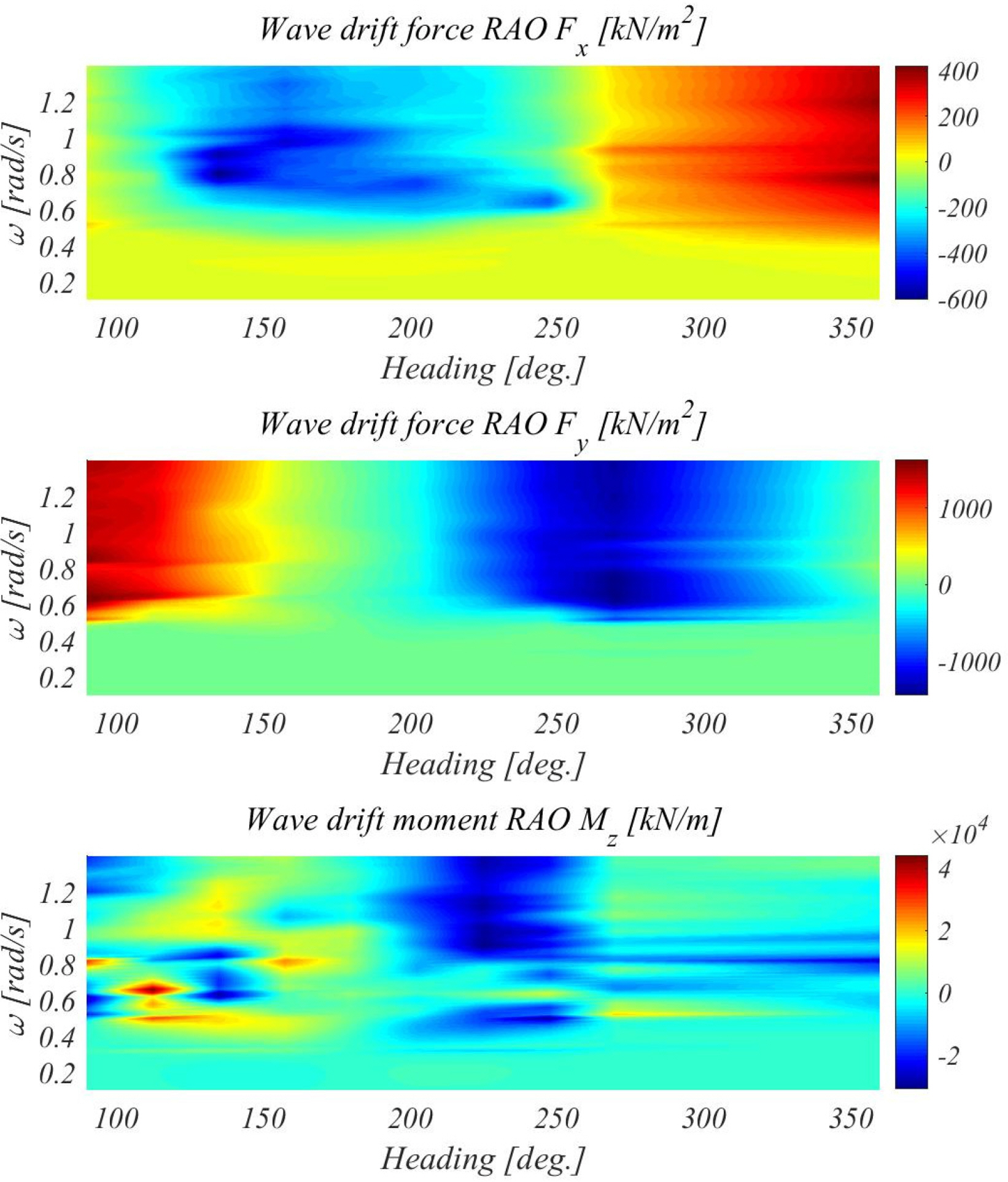
The wave drift load was calculated based on a study by Kim et al
. (2018). To calculate the wave drift load, a high-order boundary element method based on the free-surface green function (
Choi and Hong 2002) was used, and a gap flow damping term was applied to reduce the non-physical resonance of the gap of the floating body. Detailed calculations can be found in the study by Kim et al
. (2018).
For the calculated environmental load, the load acting on each floating body was also simplified to a single FLBT hull load. The individual loads of the floating bodies were replaced with a single load using
Eqs. (6)–
(8).
where
F⃗total,
F⃗FLBT,
F⃗170K,
F⃗30K are
F⃗5K the substituted horizontal load, and the horizontal loads of the FLBT, 170K LNG carrier, 30K LNG-BS, and 5K LNG-BS, respectively.
Mz,
total,
Mz,
FLBT,
Mz,170K,
Mz,30K and
Mz,5K are the substituted yawing load moment, and the yawing load moments of the FLBT, 170K LNG carrier, 30K LNG-BS, and 5K LNG-BS, respectively.
r⃗FLBT,
r⃗170K,
r⃗30K, and
r⃗5K are the distance vectors from the center of gravity of all the four floating bodies to the center of gravity of the corresponding floating body. The substituted wind and current loads are shown in
Figs. 9 and
10. For the wave drift load, the load response amplitude operator (RAO) was regenerated by the wave height of the incident wave and shown in
Fig. 11.
Based on the inertia, added mass, and environmental loads substituted by the load of a single floating body, two-dimensional planar low-frequency motion equations, i.e.,
Eqs. (9)–
(11), which consist of turret mooring and tunnel thruster, can be derived, which allow to simulate the heading angle control.
In the derived motion equation, M and Iii represent the mass and moment of mass inertia of the floating body, respectively.aij, ẍi and ẋi represent the added mass, acceleration, and velocity in each direction of motion, respectively, where the values of 1, 2, and 6 for i and j represent the surging, swaying, and yawing directions, respectively. Moreover,
Fxm,
Fym, and
Mzm represent the forces in the surging, swaying, and yawing directions, respectively, where the superscript m indicates the type of load, including the loads due to wind, current, wave, mooring, and thrust.
The heading angle of the FLBT is controlled by using the stern thruster, and accordingly, it is necessary to produce and distribute the thruster outputs. In this study, a PD controller was used to control the output of the thruster, and a Lagrange multiplier was used as the thrust allocation algorithm.


