1. Introduction
Owing to pollutants emitted from ships, global warming and environmental pollution are becoming serious problems in the field of world maritime transport. Existing ship fuels include heavy fuel oil (HFO), which is heavy oil, and marine diesel oil (MDO) and marine gas oil (MGO), which are a mixture of heavy oil and diesel; environmental pollutants are discharged from these fuels. Pollutants in the main emission gases include sulfur oxides (SOx), nitrogenoxides (NOx), and carbondioxide (CO2).
The International Maritime Organization (IMO) introduced regulations to limit emissions from ships. According to the SOx regulation, the sulfur content in fuels used in an emission control area (ECA) is limited to 0.5% as of 2020, and according to the NOx regulation, it should satisfy the ŌĆ£Tier IIŌĆØ level in general waters and ŌĆ£Tier IIIŌĆØ in the ECA as of 2016. In addition, regulations on CO2 emissions have been gradually applied by introducing the energy efficiency design index (EEDI). The EEDI refers to the amount of CO2 (gCO2/t┬Ęmile) generated by a new ship that carries one ton of cargo for one mile. The EEDI has been proposed by the IMOŌĆÖs Marine Environmental Protection Committee (MEPC) and requires a 10% reduction in CO2 emissions at each phase as of 2008 (Ivica and Ante, 2015). In the MEPC 72nd conference in May 2018, it was proposed to advance to Phase II (20% CO2 reduction) in 2020 and to Phase III (30% CO2 reduction) in 2025. Furthermore, it was proposed to advance to Phase IV (40% CO2 reduction) in 2030 instead of 2040 (IMO, 2018).
Therefore, liquefied natural gas (LNG), which is an eco-friendly fuel, is known to be a promising alternative fuel suitable for reducing the emissions of SOx, NOx, and CO2, which are pollutants emitted from ships. According to Alternative Fuels Insight (AFI) provided by DNV-GL, there are 170 LNG-operated ships and 147 LNG-propelled ships as of October 2019, and 55 more ships will be built by 2020 (DNV-GL, 2019).
Starting in September 2020, the five largest ports in Korea will be designated as ECAs. Accordingly, domestic coastal ships are also built as LNG-propelled ships, and tugboats, which account for a large proportion, will have to use the LNG fuel. Furthermore, because tugboats push and pull large ships, these boats require high power for the total weight than other coastal ships (Kifune and Nishio, 2015). This indicates that tugboats require a high-power engine and a large LNG fuel tank. As the hull is limited in space, a fuel tank suitable to the shape of a tugboat and having a high volume efficiency is required.
The pressurized fuel tank does not affect the gas fuel supply, and it can withstand the maximum design pressure even if the internal pressure of the tank increases due to boil-off gas (BOG). Therefore, BOG treatment equipment is not required. However, because the existing Type C fuel tank is a cylinder-type, and thus, its aspect ratio is fixed, it is difficult to design a free shape. Furthermore, it can only contain a small amount of LNG fuel due to its round shape (Ahn et al., 2017). A lattice pressure vessel (LPV) can be designed freely and can increase the volume ratio and volume efficiency compared with the conventional cylindrical fuel tank. In addition, the aspect ratio is not limited, allowing fuel tank designs of any size (Lee et al., 2017).
The BOG generation from an LNG fuel tank is related to the surface area according to the size of the fuel tank and insulation performance. Due to the heat inflow generated by the temperature difference between the outside temperature and the inside of the tank, the LNG, whose temperature is ŌłÆ163┬░C at atmospheric pressure, is vaporized to generate the BOG. Therefore, a double structure should be used for the fuel tank to maintain the vacuum and the heat insulating material so that the heat inflow is minimized. This method and application have been applied in LNG storage systems, and the thermal conductivity (ke) and the heat flux (q) according to the vacuum level have been verified through experiments with various insulation materials (Fesmire, 2015).
In this study, the optimum shape of the fuel tank for an LNG-fueled tugboat is designed and an LPV, which can improve the storage efficiency of the LNG, is proposed. Furthermore, by applying various insulation materials in the proposed fuel tank, the BOG generation analysis is conducted to predict the minimum BOG generation inside a fuel tank suitable for a tugboat.
2. Optimum Shape Design of LNG Fuel Tank of Tugboat
2.1 LNG fuel tank space in tugboat
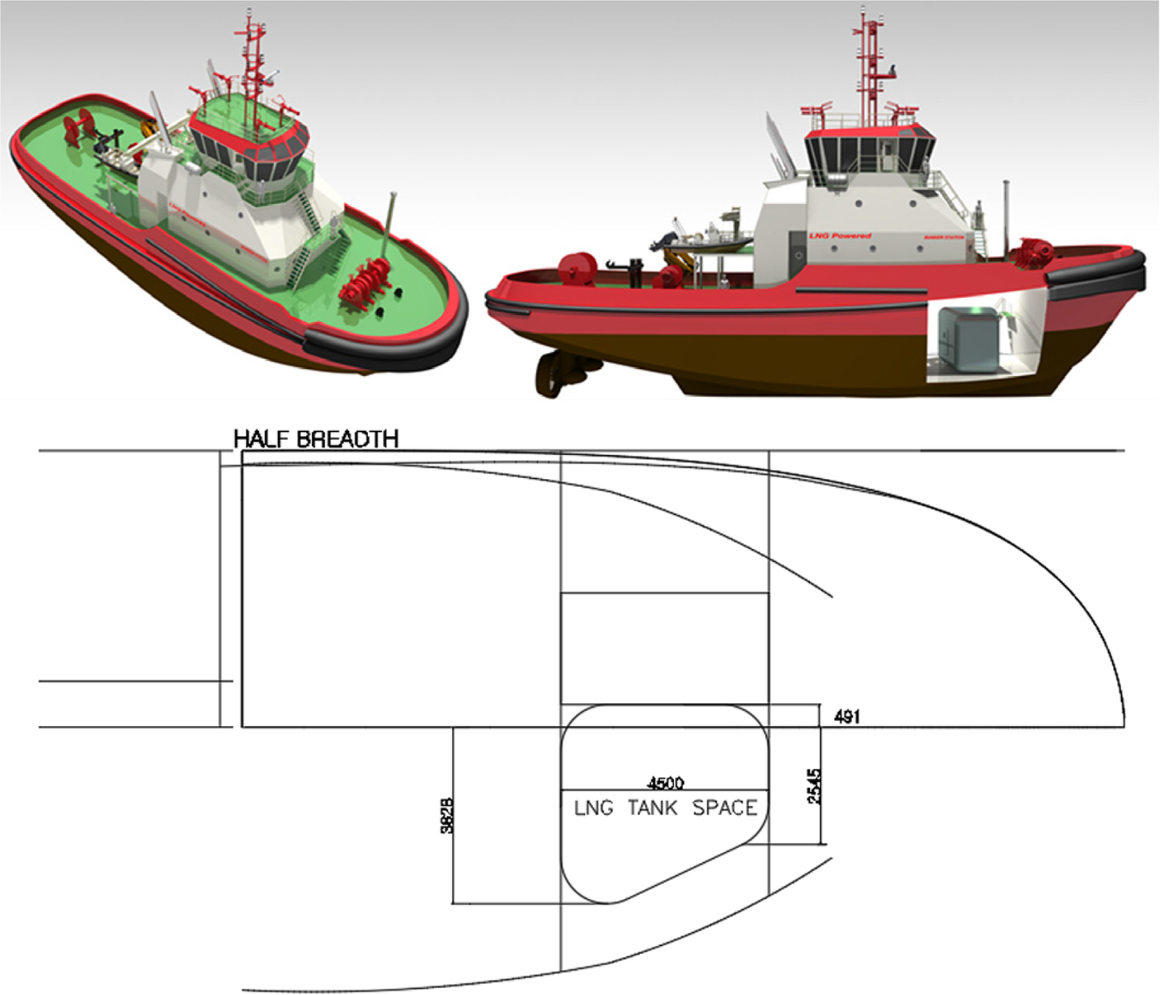
The fuel tank in ships using natural gas as fuel should be installed so that it can be protected from the risk of collision or stranding. The fuel tank designed in this study and its location were also determined based on this criterion. A detailed criterion is as follows. On the side of the fuel tank, the distance measured vertically from the side of the ship at the level of the summer load should be greater than the smaller value between B/5 and 11.5 m. For the lower surface, the distance from the side of the ship to the tank should be greater than the smaller value between B/15 and 2 m, where B is the maximum width of the ship (IGF CODE, 2015).
Fig. 1 shows the modeling of the 3.7 MW (5,000 hp) LNG-fueled tugboat and the floor plan inside the bow. The bow part of the tugboat is allocated for the LNG fuel tank and fuel supply system. As the width becomes narrower according to the linearity of the bow, the right side of the fuel tank should be designed in a proper shape to maximize the space. Therefore, the fuel tank is designed in a trapezoidal shape, and the space of the opposite fuel supply system is designed according to the volume and weight of the fuel tank. The detailed design process is addressed in Section 2.2. If a cylindrical fuel tank is installed in this space, the streamlined shape in the space will not be efficiently used. This directly affects the capacity of the fuel tank and reduces the amount of available LNG. Consequently, the LNG bunkering cycle is shortened, and the BOG generated during fueling leads to inefficient operation of the tugboat.
Unlike conventional cylindrical tanks, the LPV used in this study has a free shape. As the aspect ratio is not determined, the LPV can be designed to fit the space of the fuel tank room. Comparing the volume efficiency ratio between the cylinder tank and the LPV, the maximum volume efficiency ratio of the cylinder is 78.5%, whereas the ideal ratio of the LPV is 100% (Ahn et al., 2017). In addition, as the LPV is a pressure tank, BOG treatment equipment is not required, and thus, it is possible to maximize the fuel tank space.
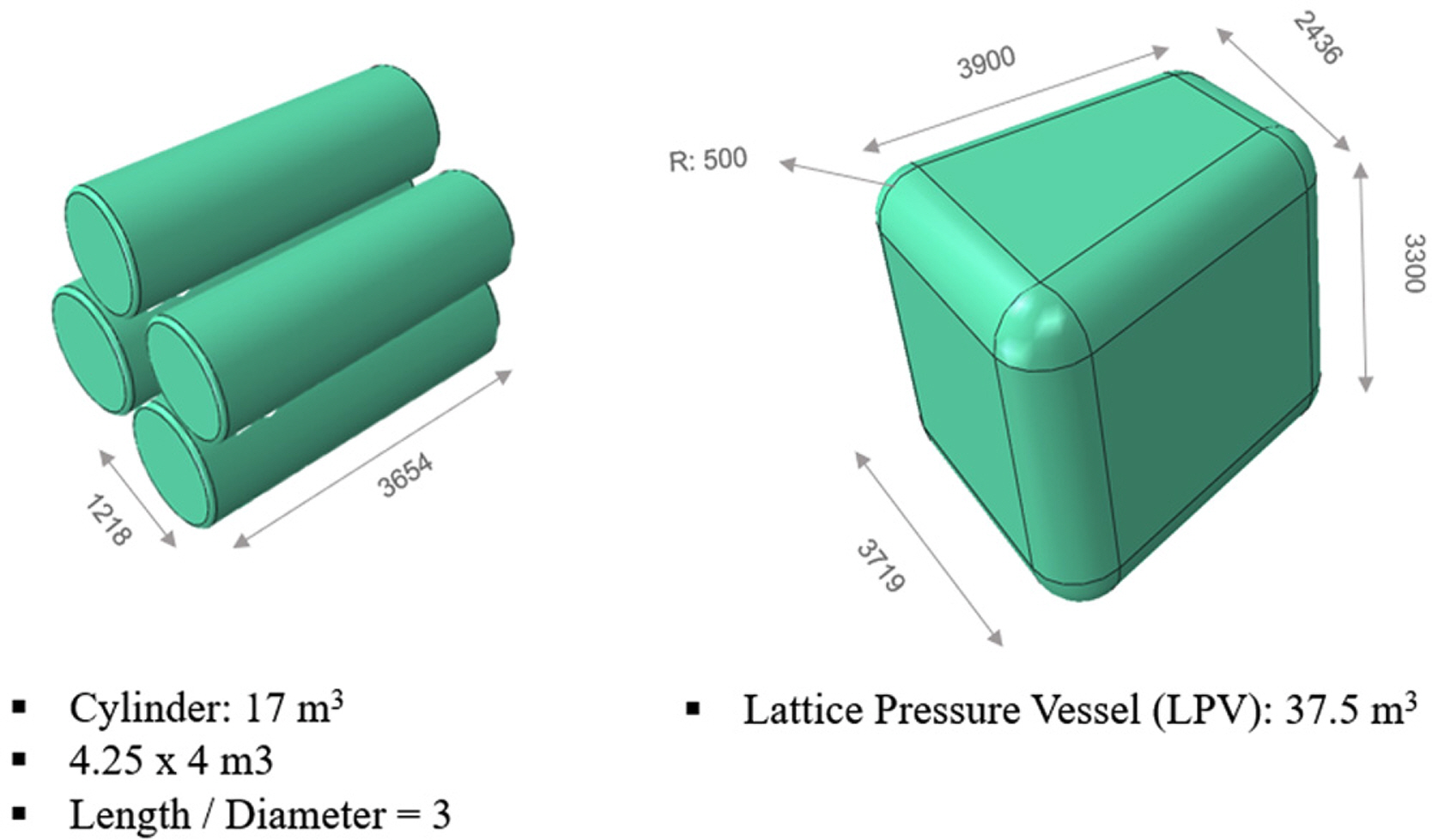
For the fuel tank of the tugboat, a trapezoidal LPV was designed based on the characteristics of the space with a side of a streamlined shape. Therefore, considering the characteristics of the fuel tank space, the difference between the cylindrical tank and the LPV is evident. As shown in Fig. 2, when the cylindrical tank is used in the fuel tank space, the volume would be 17 m3 even if the cylinders are simply stacked. In contrast, for the LPV designed in this study, the volume is 37.5 m3 because it can utilize most of the fuel tank space. In other words, the LPV is approximately 55% more space-efficient than cylinder tanks. In addition, the maintenance of the cylindrical tank is complicated because each tank is equipped with pipes and safety valves for fuel movement, whereas the maintenance of the LPV is relatively simple because it is equipped with fewer pipes and safety valves. Therefore, the LPV will incur lower maintenance cost.
2.2 Lattice pressure vessel shape design
The LPV is designed based on IGF code, IGC code, and ASME BPV code. The regulations specify the design by analysis requirements, fracture mechanics, and criteria for non-cylindrical tanks (IGF, 2015; IGC, 2014; ASME, 2013).
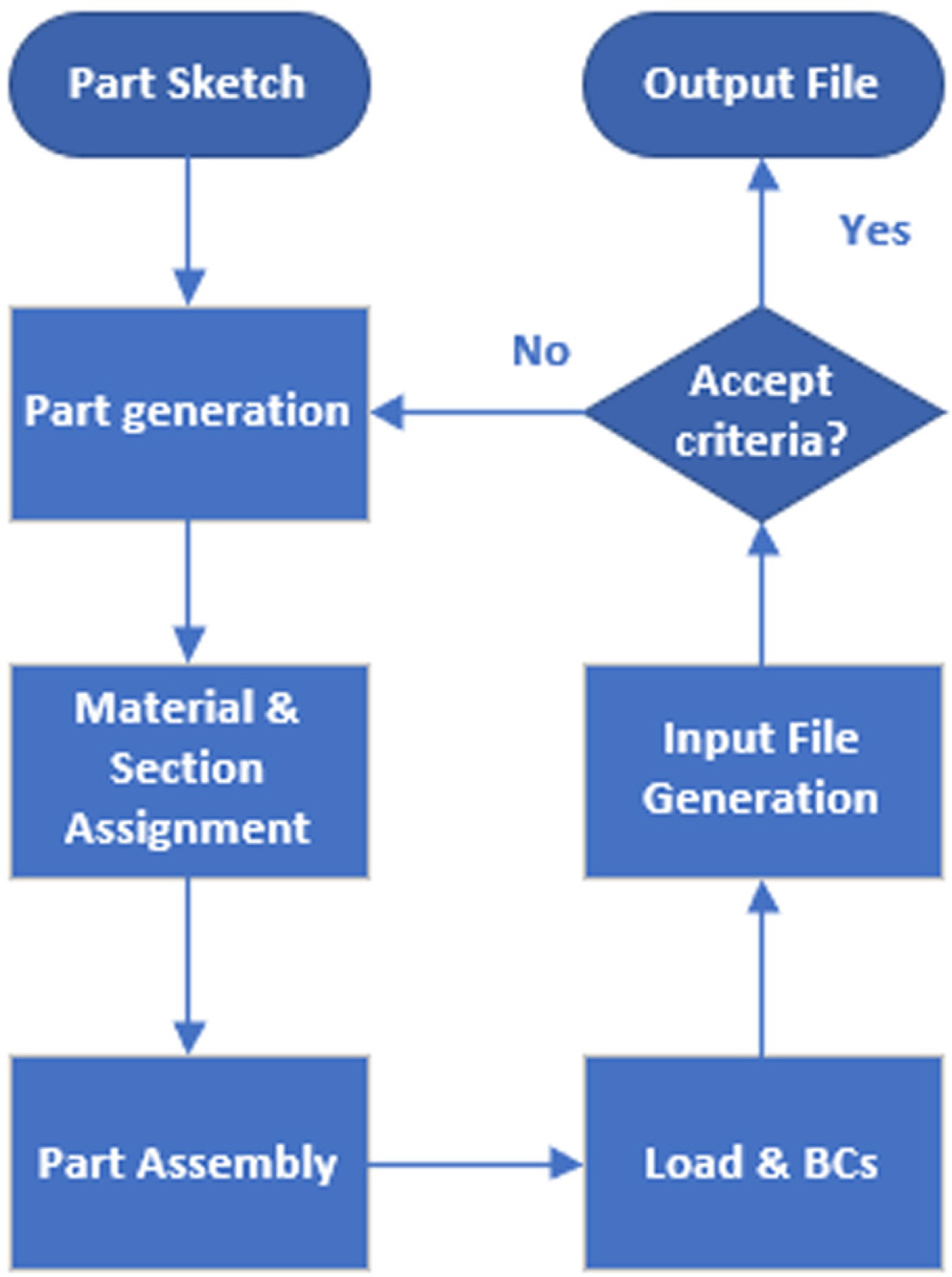
Based on the above regulations, the LPV is designed through Abaqus, a finite element analysis program. The design procedure of the LPV by finite element analysis is shown in Fig. 3. First, elements in the LPV are created and combined. The material is then selected, and boundary conditions and loads are applied. Finally, the analysis is conducted, and the design is repeated until the result satisfies the design criteria.
The accept criteria in Fig. 3 follow the Annex of the IGF Code, ŌĆ£Standard for the use of limit state methodologies in the design of fuel containment systems of novel configuration.ŌĆØ The IGF code requires three-dimensional finite element analysis, hydrodynamic analysis, buckling, fatigue, and crack propagation analysis. The analysis conducted in this study focuses on the allowable stress that does not cause plastic deformation. Specific criteria are as follows.
where
Žām= primary general membrane stress
ŽāL= primary local membrane stress
Žāb= primary bending stress
Žāg= secondary stress
ŽāUTS= ultimate tensile strength
ŽāY= yield strength
Primary general membrane stress indicates the stress generated on the plate due to internal pressure, and primary local membrane stress indicates the stress generated on the joint. The membrane stress is analyzed to have the same value in the plate thickness direction. Primary bending stress is the stress that fluctuates along the thickness direction. Primary bending stress is the stress that changes along the thickness direction. In designing the LPV, the accept criteria for primary stress generation should be satisfied so that structurally proven designs can be obtained. The accept criteria were determined by applying safety factors such as material factor and consequence factor to ultimate tensile strength and yield strength.
Therefore, the design pressure, weight, and gravity of the LNG were considered as the main load conditions in the LPV designed in this study. In addition, for the design criteria, the allowable stress was used. As the design pressure, 1 MPa, which is the maximum allowable relief valve setting specified in the IGF code, was used.
3. Analysis of BOG Generation by Insulation
3.1 Insulation Information
Various insulation materials are used in the LNG fuel tank. Currently, polyurethane foam, perlite powder, glass bubble, and aerogel blanket are widely used for cryogenic insulation. In addition, to minimize the heat inflow generated by the temperature difference between the inside and outside, the vacuum level in the insulation is increased and the insulation is used in the LNG fuel tank. This is a test-proven method, and in 2015, perlite powder, glass bubble, aerogel blanket, multi-layer insulation, fiberglass, and layered composite insulation (LCI) were applied to a cryogenic liquid storage container and the heat conduction effect according to the vacuum level was tested (Fesmire, 2015). In the case of polyurethane foam, there was a case where the thermal insulation performance was tested not only in the LNG industry but also in the liquid hydrogen temperature range. In this case, the thermal insulation performance was tested under vacuum as well as atmospheric pressure (Tseng et al., 1997). Therefore, this study analyzed the amount of BOG generated from the fuel tank according to various insulators. Aerosol, perlite powder, glass bubble, and polyurethane foam were used as insulation materials. Each insulation material was analyzed in atmospheric pressure and vacuum. The insulation properties are shown in Table 1.
3.2 BOG generation analysis
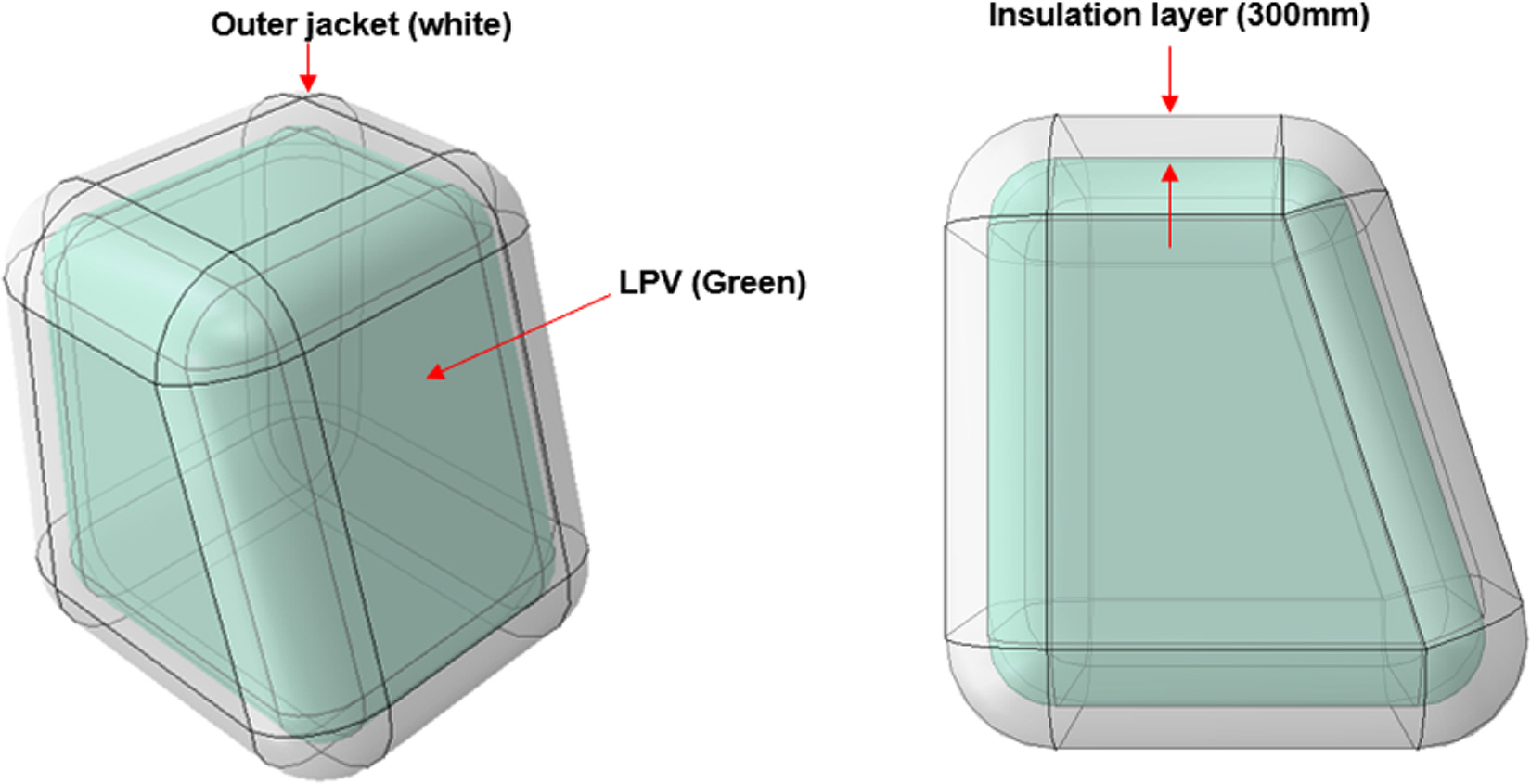
Fig. 4 shows a tugboat LNG fuel tank with an insulation layer and outer jacket. The LPV, which is a fuel tank, is protected by a uniform insulating layer and outer jacket to reduce heat inflow. The information about the fuel tank with the insulation layer is summarized in Table 2.
The amount of BOG generated is calculated using external temperature, LNG temperature, density, and phase change heat. The relevant information is summarized in Table 3. In this study, it is assumed that heat transfer by convection and radiation has no effect considering that the insulation layer has sufficient thickness. In other words, the amount of BOG generated was analyzed by considering the heat transfer by conduction alone. It was assumed that the LNG level is 90%, the temperature gradient in the tank would be negligible, and the outside temperature would be 45┬░C. The equation of state for the thermodynamic properties of the LNG used in the calculation is the Peng-Robinson equation. Based on this information, the derivation process of the amount of the generated BOG is given in Eqs. (8)ŌĆō(11). The thermal resistance in the one-dimensional conduction heat transfer can be derived using Eq. (8). Assuming that all sides of the LPV are planar, the thermal resistance (t) can be determined from the insulation thickness (k), thermal conductivity (A), and cross-sectional area (R). Eq. (9) helps calculate the heat intrusion (q). Dividing the thermal resistance (Tamb) obtained from Eq. (8) by the difference between the external temperature (R) and the temperature of the LNG (TLNG) results in thermal intrusion (q). The equation for calculating the BOG, or the LNG evaporating due to heat intrusion (q), is shown in Eq. (10). The BOG calculated using Eq. (10) is the amount of the LNG that evaporates during a day and is calculated by the ratio of the heat intrusion (q) and the latent heat of evaporation of the LNG (hfg). Finally, to calculate the boil-off rate (BOR), the BOG relative to the amount of the LNG in the fuel tank should be calculated using Eq. (11). The LNG in the fuel tank is obtained by multiplying the density of the LNG (ŽüLNG), the volume of the fuel tank (V), and the liquid fraction (LLF).
where
t insulation thickness (m)
k conductivity (W/m┬ĘK)
A surface area (m2)
R thermal resistance (K/W)
Tamb ambient temperature (K)
TLNG temperature (K)
q heat ingress (kW)
hfgheat of vaporization (kJ/kg)
LLF liquid level fraction
Žü density (kg/m3)
V volume (m3)
BOG boil off gas (kg/day)
BOR boil off rate (%/day)
4. Results and Discussion
4.1 Shape design result of fuel tank
Fig. 5 shows the LPV designed in this study. The designed LPV is trapezoidal by considering the shape of the fuel tank space, and it is 3.3 m in height, 3.9 m in length, 3.7 m in the lower side and 2.4 m in the upper side, and the radius is 0.5 m. The component is composed of a 19-mm-thick outer surface and 15-mm-thick stiffner. Consequently, the volume and weight of the LPV were estimated to be 37.5 m3 and 25.37 ton, respectively. Table 4 shows the materials, density, physical properties, allowable stress, design pressure, and LNG density information in the design. The load conditions used in the design include internal pressure, the weight of the LNG, and gravity.
Fig. 6 shows the finite element analysis results of the LNG LPV. In the results, the von Mises stress indicates that the safety factor is applied to the combination of bending stress and membrane stress. Therefore, to satisfy the design specification presented in the IGF code conservatively, the von Mises stress must be within the allowable stress.
The LPV designed in this study has a maximum von Mises stress of 204.3 MPa and does not exceed 205 MPa, the allowable stress of SUS304. In conclusion, the combination of bending stress and membrane stress caused by internal pressure, the weight of the LNG, and gravity is considered to satisfy the allowable stress. Thus, the structural design of the LPV having the design pressure of 1 MPa is completed.
4.2 BOG generation result
The results of the amount of BOG generated with various insulators at atmospheric pressure are summarized in Table 5. BOR is 0.518 %/day for aerosol, which has the lowest thermal conductivity, and 1.649 %/day for perlite powder, which has the highest thermal conductivity. Table 6 shows the results of the amount of BOG generated when vacuum is applied to various insulations. In the vacuum state, as the thermal conductivity is lower than that at atmospheric pressure, the BOR is also low. The BOR is approximately 0.094 %/day for the glass bubble with the lowest thermal conductivity and 0.424 %/day for polyurethane foam with the highest thermal conductivity.
The results of the amount of BOG generated according to the vacuum level and insulation material can be used for the tugboat operation plan. If the tugboat fuel supply cycle is established, a target BOR will be designed, which leads to the degree of a vacuum and selection of the insulation layer. As a future study, if the target BOR of the tugboat fuel tank is determined, it will be possible to select the optimum insulation condition and set the operation strategy of the tugboat through economic evaluation according to various insulation materials and vacuum level.
5. Conclusion
In this study, the optimum shape of a fuel tank for an LNG-fueled tugboat was designed and an LPV was proposed to improve the volume efficiency. In addition, the minimum amount of BOG generated was estimated according to the heat inflow by applying various insulation materials to the proposed fuel tank.
The optimum shape for the 3.7 MW (5,000 hp) tugboat is a trapezoid with a volume of 37.5 m3 and a fuel tank is designed with rounded corners to minimize surface area. The surface area of the fuel tank was 79.8 m2 when the LPV was applied, and the volume efficiency in the same fuel tank space was increased by 55% compared with that of the cylindrical pressure vessel. The finite element analysis considering the fuel tank internal pressure, weight of the LNG, and gravity resulted in a von Mises stress of 204.3 MPa, which is within the allowable stress and thus confirmed the safety of the design.
Various insulation materials were applied to the fuel tank to calculate the amount of BOG generated. Consequently, the glass bubble generated the smallest amount of BOG with 14.3 kg/day at 0.013 kPa and polyurethane foam generated the highest amount of BOG with 64.4 kg/day. Similarly, from the BOR calculation results, it was observed that polyurethane foam showed the highest value of 0.42 %/day, whereas perlite powder and aerosol insulation showed a similar amount of generated BOG.
The use of high-performance insulation minimizes the amount of BOG generated, which eliminates the need for BOG treatment equipment and increases the safety of the fuel tank. However, from an economic point of view, the initial investment cost of the fuel tank can be increased. Therefore, research on the optimum insulation material and insulation condition is necessary.