Study on Stopping Ability of a Ship Equipped with Azimuth Propeller
Article information

Abstract
An azimuth propeller can generate thrust in all directions by rotating its housing with an electric motor. An azimuth propeller can be operated using several methods to stop a ship. This study aims to derive an efficient method to stop a ship safely using an azimuth propeller through full-scale maneuvering trials with the research vessel “NARA” of Pukyong National University in 4.63 m/s (9 kts). Five methods with different azimuth propeller operations were tested to stop the ship. The test results confirmed that the simultaneous use of the thrust and the hydrodynamic force acting on the strut is the most effective method to stop the ship.
1. Introduction
An azimuth propeller refers to a propeller capable of generating thrust in all directions by rotating its housing through an electric motor. It is used for offshore specialized vessels because it improves berthing and maneuvering performances in the port, and it enables dynamic positioning. A maritime autonomous surface ship, which has recently attracted attention, is likely to be equipped with a bow thruster and an azimuth propeller, rather than a general propulsion and steering gear system, to implement automatic berthing and un-berthing. Therefore, continuous studies will be necessary for the maneuvering performance of ships equipped with an azimuth propeller.
The maneuvering performance of ships are primarily categorized into turning, course changing, and stopping abilities. As a ship is typically equipped with two or more azimuth propellers, various methods can be used to manipulate the propellers for turning and course changing, as well as for stopping a ship. According to ship captains and maritime pilots, ships equipped with azimuth propellers can reduce the track reach by 50% or more at the time of emergency stop compared with ships equipped with general single-shaft propellers, depending on the stopping method (Nowicki, 2014). Previous studies on the stopping ability of ships have focused primarily on methods using maneuvering mathematical models (Nakato et al., 1976; Yoshimura, 1994). Recent studies have investigated methods for estimating the stopping ability of full-scale ships using the free-running model test or computational fluid dynamics (Ueno et al., 2017; Sun et al., 2018). However, few studies have reviewed methods for improving the stopping ability of ships through full-scale maneuvering trials using azimuth propellers.
This study aims to derive an effective method to safely stop a ship through a full-scale maneuvering trial using azimuth propellers. The full-scale maneuvering was performed using the research vessel “NARA” of Pukyong National University. Five different approaches were tested to stop ships by varying the operation of azimuth propellers. Using the test results, the track reach of the ship was analyzed to determine the most effective method.
2. Preparation of Full-Scale Maneuvering Trial
2.1 Test vessel and azimuth propeller
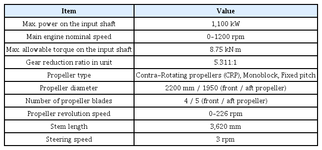
This study was conducted using the research vessel NARA of Pukyong National University. The general arrangement and specifications of NARA are shown in Fig. 1 and Table 1, respectively.
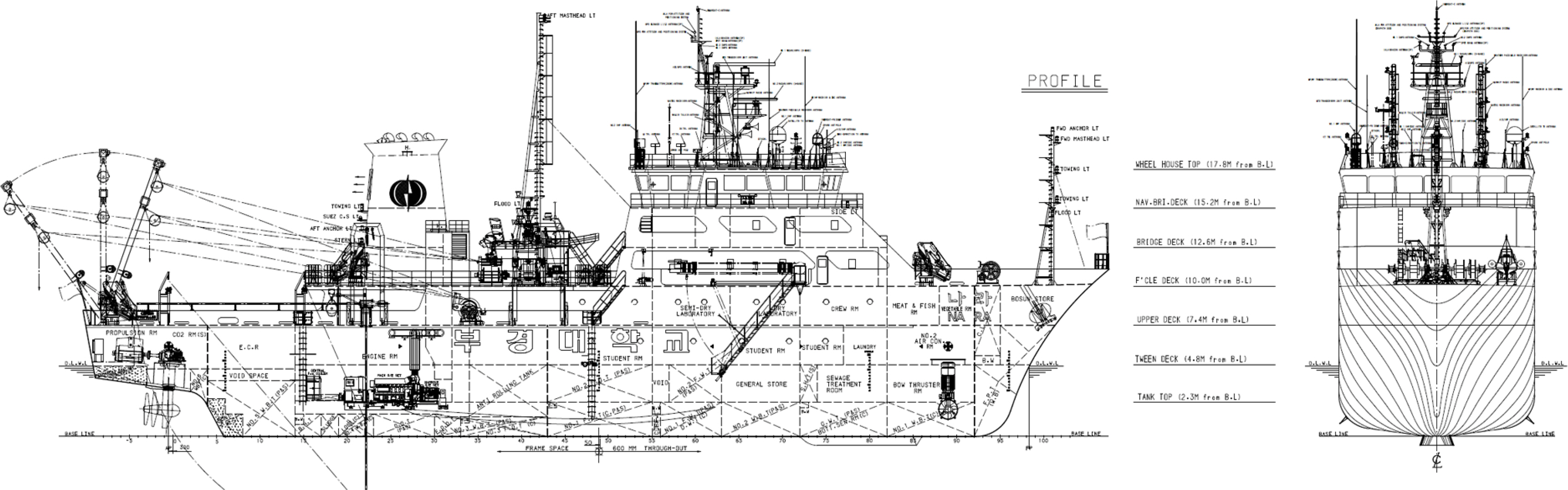
General arrangement of NARA

Principal dimensions of NARA
NARA was equipped with two Rolls-Royce US 155 contra-rotating propellers (CRPs), which were azimuth propellers equipped with a pair of CRPs. The appearance and specifications of the azimuth propeller of NARA are shown in Fig. 2 and Table 2, respectively.

Azimuth propeller of NARA
Azimuth thruster units of NARA
2.2 Test methods
The International Maritime Organization enacted and legislated steering performance standards (maneuverability resolution) in 1994, providing the minimum maneuvering performance required for ships. Crash astern and stopping inertia tests were performed to identify the stopping ability, and the crash astern test was conducted for test-driving commercial vessels. The crash astern test method is as follows. The propeller is windmilled by discontinuing fuel supply to the engine of the ship moving forward at a certain speed, and the engine rotation is reversed to stop the ship when the engine reaches approximately 20% of the rotational speed at the maximum continuous rate. The data to be derived from the crash astern test are defined in Fig. 3, including the track reach, head reach, and lateral deviation during the stop (ITTC, 2017).

Definitions used in stopping trials (ITTC, 2017)
The stopping process of a ship, as previously described, is a general method applicable to all types of vessels. For ships equipped with azimuth propellers, additional ship stopping methods exist. The first method is to stop a ship by rotating an azimuth propeller by 180° to change the thrust direction when the angle of the azimuth propeller in the moving-forward situation is defined as 0°. Although this method improves the stopping ability in comparison with the case of using reverse propulsion, an excessive load can be applied to the propeller blades when rotating the azimuth propeller. The second method is to simultaneously apply the reverse propulsion and rotate the azimuth propeller at a certain angle to additionally use the hydrodynamic force acting on the housing and strut to stop a ship. The rotation of the azimuth propeller at a certain angle results in the generation of lift and drag owing to the angle of attack on the propeller housing and the strut having a shape similar to the blade surface, which can be used to stop the ship. In this study, the five methods used by Nowicki (2014) were tested to stop the ship. Table 3 describes the applied stopping procedures.

Case description of the stopping procedure (Nowicki, 2014)
3. Results of Full-Scale Maneuvering Trial
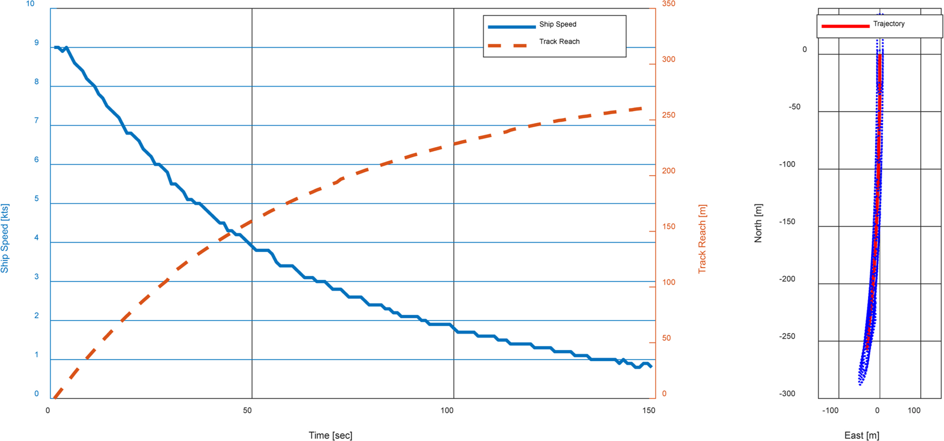
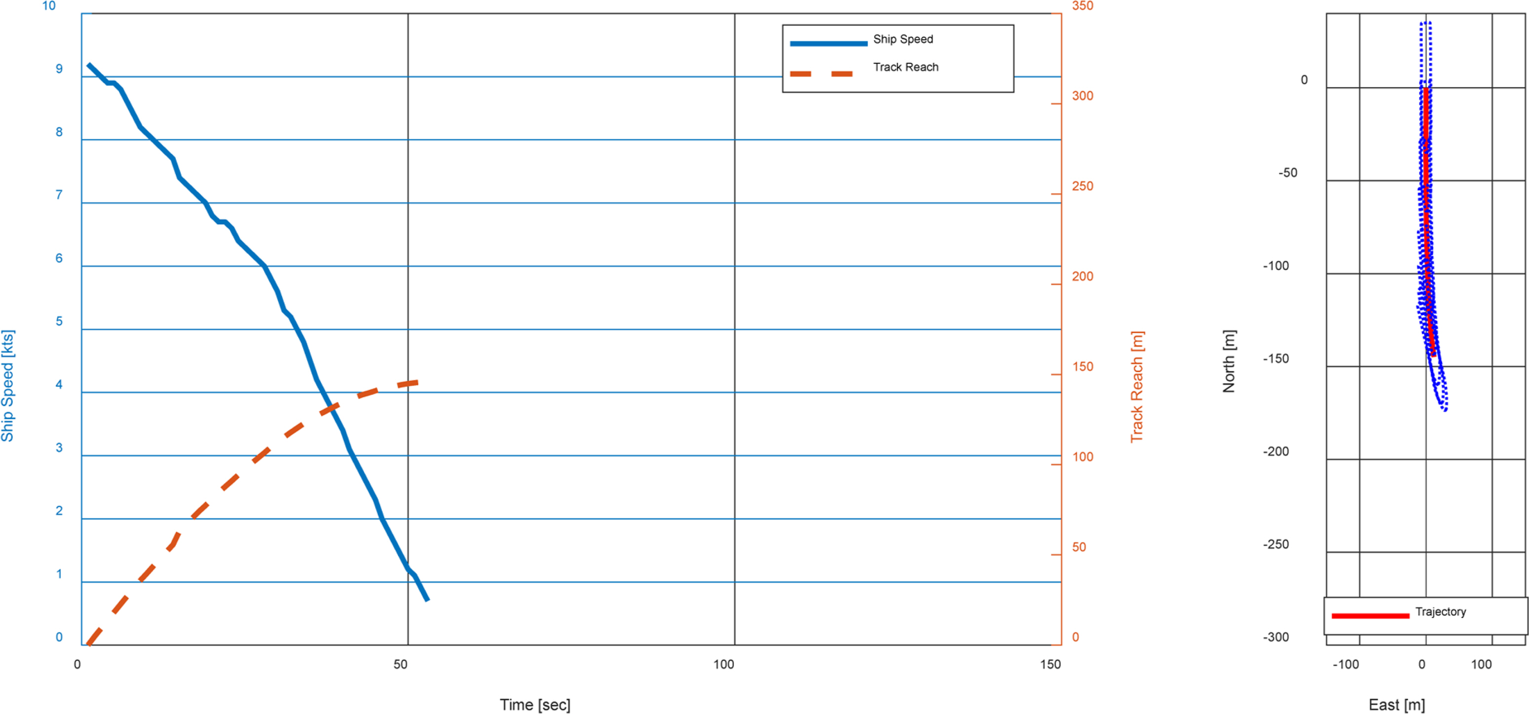
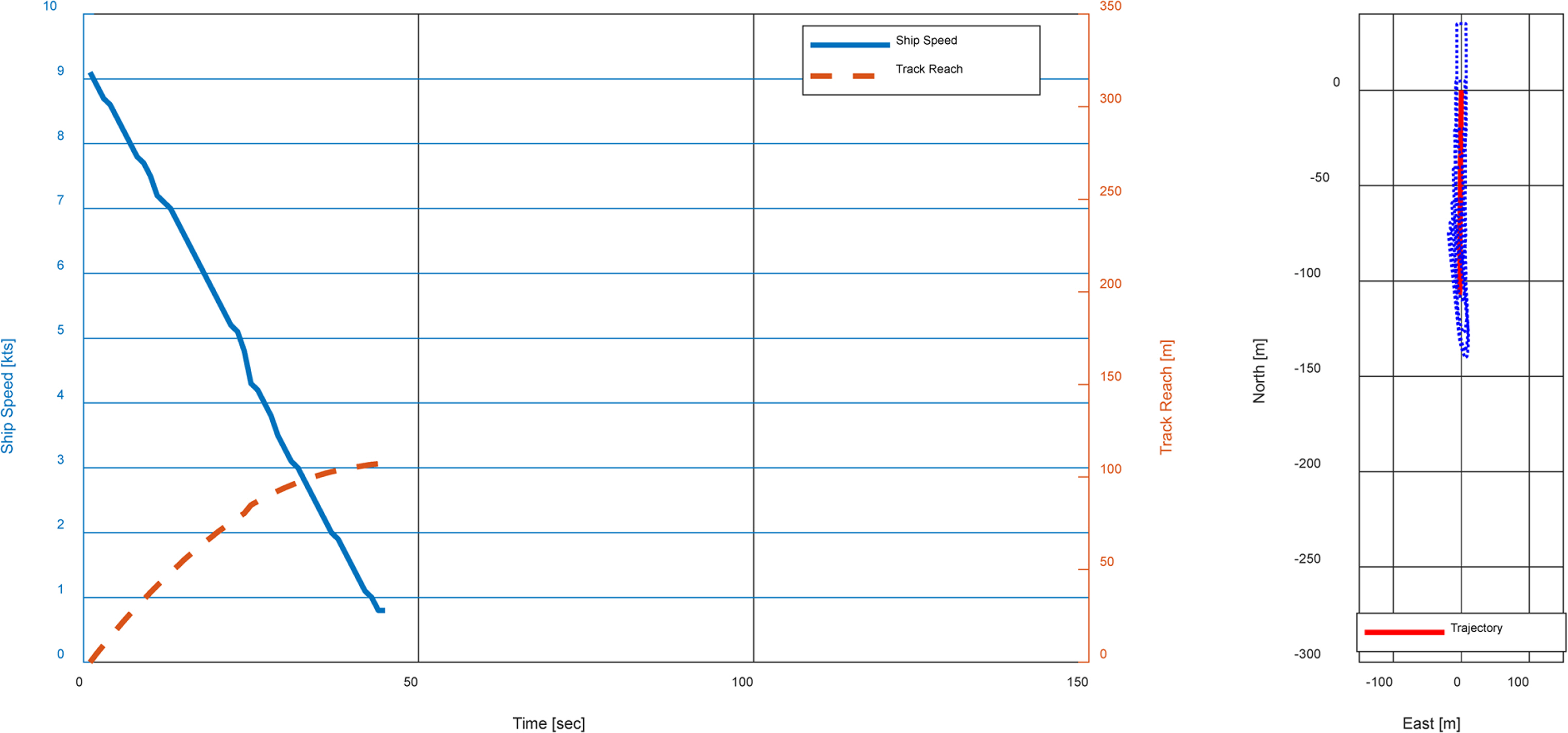
The full-scale maneuvering trial was conducted on April 23, 2019, near Mijo-myeon in the Southern coast (near latitude: 34.72°, longitude: 128.11°). During the trial, the average wind speed and wind direction in this region were 6.5 m/s, and 15.8°, respectively, and no current was measured. The initial speed was set at 4.63 m/s (9 kts), which was approximately 65% of NARA's service speed. According to the provisions of the International Maritime Organization (IMO, 2002), a stopping test must be conducted at a speed equivalent to 90% of the service speed; however, our test was conducted at 4.63 m/s (9 kts) owing to severe hull vibrations at that speed. The measurement period of the test data was 1 Hz. The position information of this vessel were measured by latitude and longitude coordinates, but they were converted into the Universal Transverse Mercator coordinates in this study. The measured velocity was the ground speed, but environmental disturbances such as wind and current in this region prevented the vessel from stopping accurately based on the ground speed. Hence, the track reach, lateral deviation, and time to dead were derived assuming that the vessel stopped when the vessel speed reached 0.46 m/s (0.9 kts) or less, which was 10% of the initial speed. Figs. 4 to 8 show the graphs of the test results by each stopping method. The left-side graph shows the vessel speed and track reach, and the right-side graph indicates the trajectory of the ship.
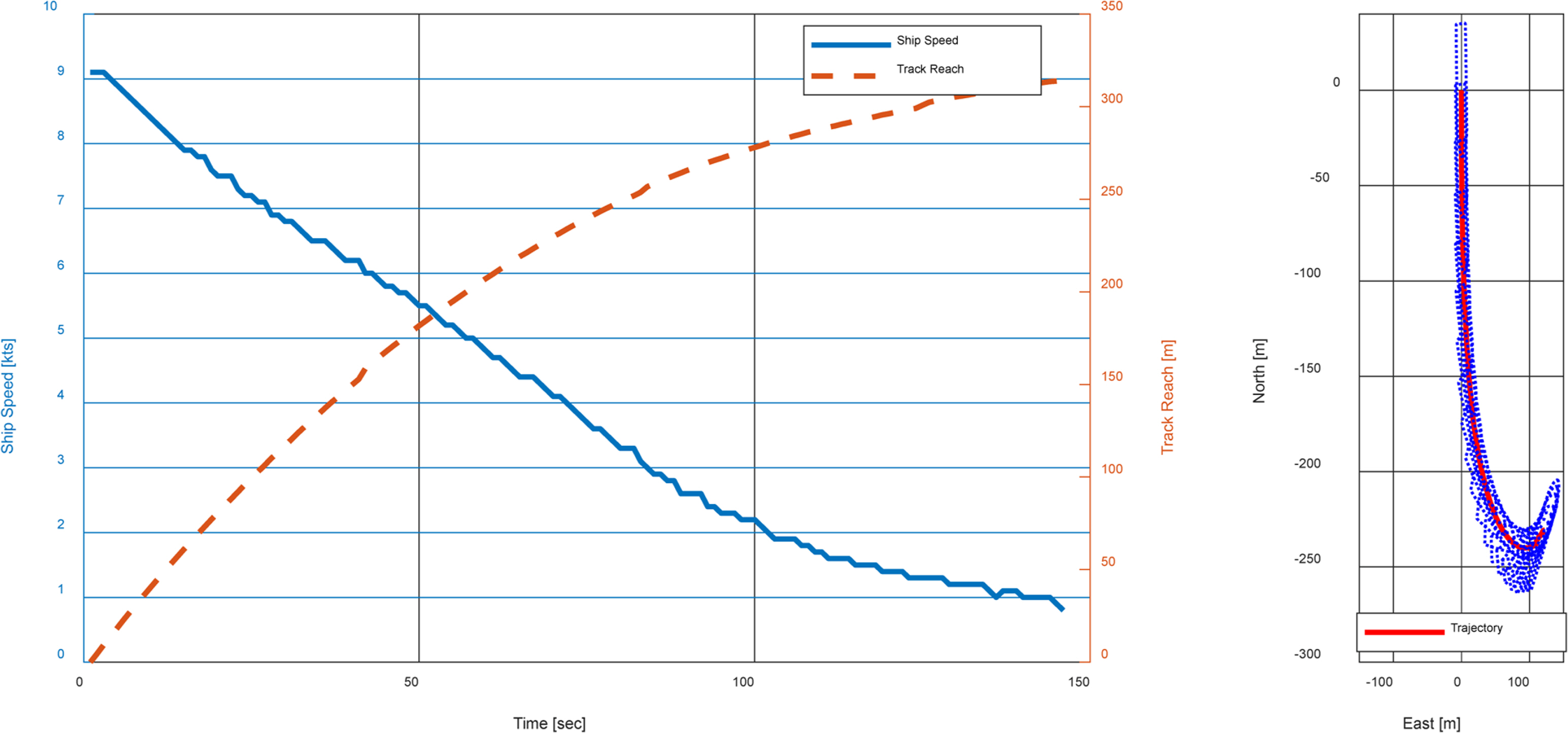
Stopping test results for 1st stopping mode
Stopping test results for 2nd stopping mode
Stopping test results for 3rd stopping mode

Stopping test results for 4th stopping mode
Stopping test results for 5th stopping mode
Table 4 shows a summary of the track reach, lateral deviation, and time to dead for each stopping method.

Stopping test results
In Cases 1 and 2, which stop the ship by rotating the azimuth propeller 90° outward, the hydrodynamic force acting on the strut and the housing were used to stop the ship. In Case 3, which stops the ship by rotating the azimuth propeller 180°, and in Case 4, which stops the ship by reverse propulsion, the thrust of the propeller was used directly to stop the ship. In Case 5, which stops the ship by rotating the azimuth propeller 30° outward while reversing the propellers, both the hydrodynamic force acting on the strut and the housing as well as the thrust of the propeller were used to stop the ship. The difference between Cases 1 and 2 is the propeller rotation. The acceleration of the fluid due to propeller rotation was added to the movement speed of the hull, thereby forming an angle of attack in the propeller housing and the strut. The difference in the angle of attack of the propeller housing and the strut between Cases 1 and 2 changed the hydrodynamic force in the ship’s stopping direction, resulting in a difference in the track reach. The comparison of the results from Cases 3 and 4 reveals that the method of stopping the ship using reverse propulsion reduces the track reach by 21% compared to that of rotating the azimuth propeller by 180°. This difference is considered to be caused by the difference in the time required for the thrust of the propeller to act in the stopping direction of the ship. As the steering speed of the azimuth propeller was 3 rpm according to the specifications listed in Table 2, approximately 10 s was required to rotate the azimuth propeller by 180°. In Case 3, reverse propulsion began after the rotation of the azimuth propeller was completed. Fig. 6 shows that the speed reduction rate increased after approximately 25 s. Meanwhile, because the reverse propulsion in Case 4 began immediately after a deceleration in rotation when the stopping test was initiated, the thrust generation time could be shortened in the stopping direction of the ship, in comparison to Case 3. Furthermore, in both methods, the slipstream of the propeller was directed to the stern, which affected the pressure distribution on the stern and hence the resistance acting on the hull. The propeller in Case 3 was located closer to the hull than compared with Case 4, which could affect the increase in distance traveled by the ship before stopping. The results of Case 5 show that this method is the most effective for stopping the ship among all the methods. Rotating the azimuth propeller by 30° reduces the thrust in the stopping direction by approximately 13%, but the thrust of the propeller housing and strut due to the angle of attack acts additionally in the direction opposite to the traveling direction of the ship. The overall results confirmed that the methods of Cases 3, 4, and 5, which directly used the thrust of the propeller to stop, was more effective in stopping ships compared to the methods of Cases 1 and 2, which used the hydrodynamic force acting on the propeller housing and the strut to stop the ship.
4. Conclusion
To determine the efficient operation method of azimuth propellers to stop a ship, a full-scale maneuvering trial was conducted using the research vessel NARA of Pukyong National University. First, the method of directly using the thrust of azimuth propellers to stop the ship was more effective than the stopping method using the hydrodynamic force of the propeller housing and strut. Next, the method of stopping the ship using reverse propulsion was more effective than rotating the azimuth propeller by 180°. Subsequently, the method of simultaneously using the thrust of the azimuth propeller, the hydrodynamic force of the propeller housing, and the strut was the most effective in stopping the ship.
The limitations of this study are as follows. First, the conclusions of this study might not be applicable to all ship speeds. The change in ship speed varied the change in the angle of attack between the propeller housing and the strut, which could yield different test results. Next, the operation angle of 30° for the azimuth propeller, which was applied in Case 5, could not be guaranteed to be optimal for stopping the ship. The method in Case 5 might yield different results depending on the operation angle of the azimuth propeller because it simultaneously used the thrust of the propeller and the two thrusts acting on the adjuncts. Therefore, further studies are required to systematically conduct tests for each speed and operation angle of the azimuth propeller and to derive the optimal method for stopping ships by summarizing the results in a lookup table.
Acknowledgements
This study was funded by the National University Promotion Program for Pukyong National University in 2019.
Notes
Author ORCIDs and Contributions
Author name ORCID Contributions
Park, Jong-Yong 0000-0002-5200-6012 ③④⑤
Oh, Pilgun 0000-0001-8601-8380 ⑤
Kim, Taejin 0000-0001-8222-8647 ⑤
Lee, Jun-Ho 0000-0002-3747-167X ①②
① Conceived of the presented idea or developed the theory
② Carried out the experiment or collected the data
③ Performed the analytic calculations or numerical simulations
④ Wrote the manuscript
⑤ Supervised the findings of this study