A Feasibility Review for an Uneven Baseline Basis Minimal Ballast Ship
Article information

Abstract
Although there are many kinds of advanced ballast water management systems, pioneering studies for ballast-water free ship and minimal ballast water ship concepts are in progress. In this study, the existing alternatives of ballast water are reviewed and a new design concept is studied on the basis of the existing bulk carrier hull form. To develop a new design alternative which has minimal ballast for ballast water discharge free operation, the new concept should have technical feasibilities that are related to the role of the ballast water, berth access, loading constraints, etc. For this purpose, a simplified systems engineering basis design approach is adopted using a business model as the system analysis and control tool. To check the performance feasibility of the new concept, ship resistance performance is reviewed based on a model scale ship resistance performance analysis.
1. Introduction
Because the measures from the Ballast water management (BWM) convention are being enacted in order to reduce the environmental damage caused by the global movement of marine life in the ballast water of ships (Albert et al., 2013), the negative effect of treated ballast water on the marine environment is another urgent issue (Werschkun et al., 2014). Notably, research on non/minimal ballast water vessels is actively underway in response to the D-1 or D-2 discharge standards of the convention. When considering the role of ballast water, as shown in Table 1, the ballast water contributes to the ship’s stability via proper maintenance of the draft and the center of gravity of a ship during voyage. Another aim of the ballast water is to maintain the appropriate immersion depth of the propeller for propulsion efficiency. Ballast water is also used to adjust the trim and heel of a ship. The bending moment and shear force can also be adjusted by the ballast water.

Roles of the ballast water in a ship (Isbester, 2010)
Depending on the ship types and routes, generally, 30% to 40% of the deadweight tonnage (DWT) is used as ballast water (Kerr, 1994). Many pioneering studies have been conducted to meet the D-1 or D-2 discharge standards of the BWM convention without needing to discharge the environmentally harmful ballast water. Table 2 shows alternatives for the BWM methods (GEF, U. and IMO, G.P., 2011).

Alternatives for the BWM methods [derived and edited from GEF, U. and IMO, G. P. 2011]
Among the various alternatives, in the case of ‘no or minimal discharge’ alternatives, the minimal ballast water ship (MIBS) and non-ballast water ship (NOBS) (Shingo, 2014) of a ‘storm ballast’ are considered to be practically applicable alternatives. Though there are some constraints for berthing and loading, in 2018, a NOBS concept basis ballast water-free ‘7,500 cubic meter liquefied natural gas (LNG) bunkering vessel’ was launched for commercial purposes (https://pulsenews.co.kr). For the ‘continuous flow’ type alternatives, ‘The Variable Buoyancy Ship Concept’ of ‘longitudinal trunks’ is remarkable. For the trim and heel control, the concept has been shown to adequately control the trim and draft (Parsons and Kotinis, 2011a; Parsons and Kotinis, 2011b). In this study, a new design concept for ‘no or minimal discharge’ alternatives is studied while considering the ship’s size and operational conditions.
2. Feasibility Study
To design a new minimal ballast vessel, a ship must be designed that has the functions of ballast water without or with the minimum use of ballast. The perspectives of performance, ship stability, resistance, trim and heel controllability, berth access and loading constraints should be considered. Technical complexity and cost related matters are also considered to ensure technical and economic feasibility.
To compensate for the existing BWM alternatives’ penalties, an appropriate approach and design process are required. In a systems engineering process, it is essential to identify, validate, and verify the various constraints of shipbuilding and operation in the design phase for the development of minimal ballast water vessel. Generally, the systems engineering basis design process involves a “system analysis and control tool”, which allows for the effective management of various design entities from various viewpoints, including technical and economic feasibility (Leonard, 1999; Kang et al., 2016). In this study, the business model was used as a system analysis and control tool, which was suggested by Kang et al. (2016). The business model consists of six elements: the design of a new concept for a minimal ballast vessel (Task); the required value of the enhanced berth access and loading capability compared to the existing ‘MIBS’ (Value); the expected revenue of the designed concept, such as a decrease in the ecosystem disturbance (meeting D-2) and the reasonable hull build cost (Revenue); the available and considered infrastructure, such as port facilities, ships in operation, rules and regulations, ship yards (Infra); the channels to enable the design concepts, such as technical and economic feasibilities (Channel); and the stakeholders of the task, including ship owners, ship builders, port authorities, classification societies, and fishing industries (Stakeholder). The factors considered in this study are shown in Table 3.
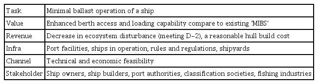
Business model for a new non / minimal ballast ship design
By adopting a business model for the systems analysis and a control tool for the design process, the ISO/IEC 15288-based ‘Vee’ design process was adopted and modified, as shown in Fig. 1. In the early phase of the design process, the measure of effectiveness (MOE), key performance parameters (KPPs), measure of performance (MOP) and technical performance measures (TPMs) should be identified in order to validate and verify the feasibility of the design results in the early phase of the design process. During the design process, all the design aspects should be analyzed and determined within the boundaries of the defined business model.
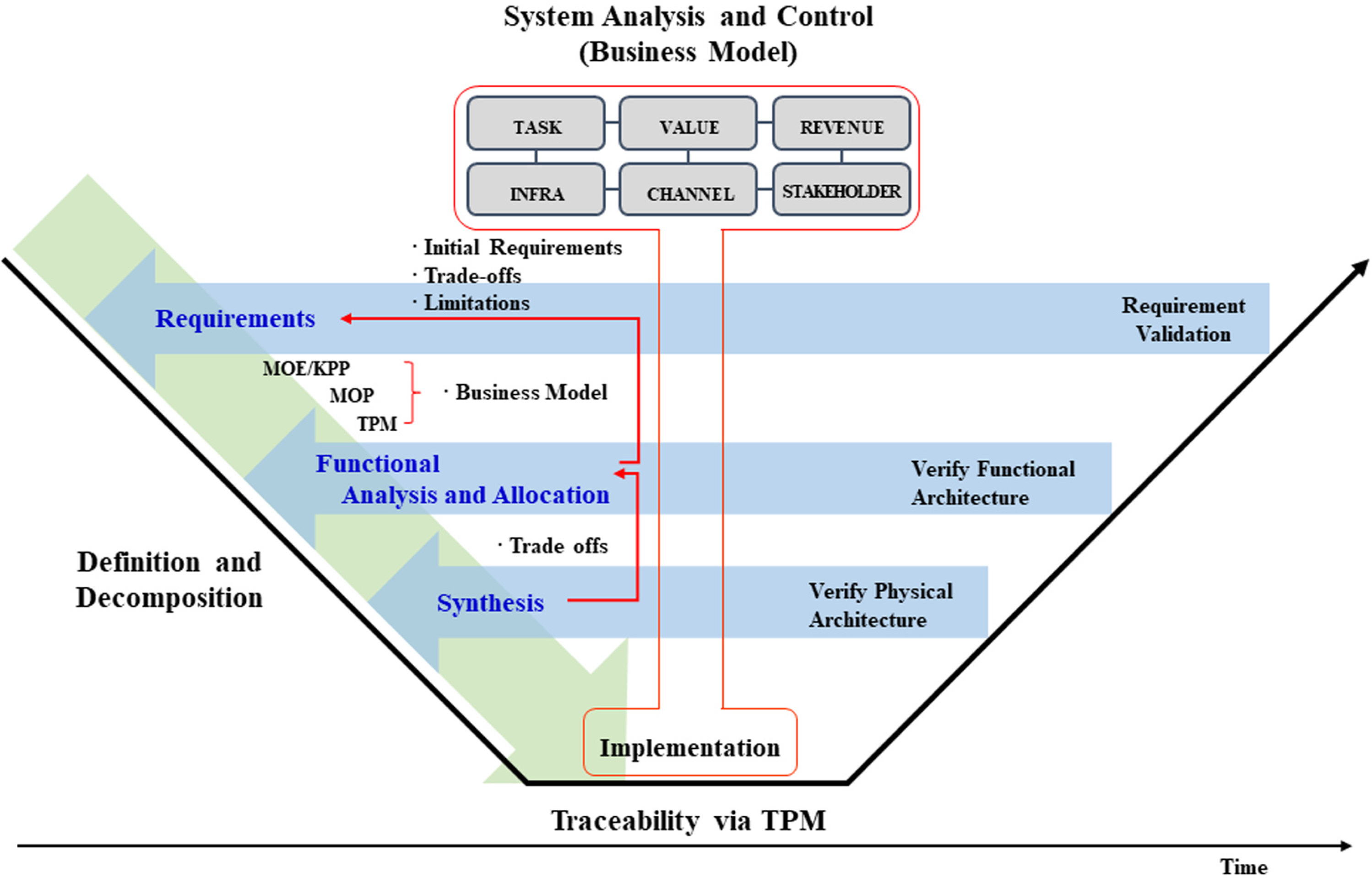
Design process for a new minimal ballast ship design [derived and edited from (Kang et al., 2016)]
2.1 Requirement analysis
To achieve this goal, eight requirements were derived, as shown in Table 4. R1 to R7 are the general requirements for a non/minimal ballast water ship. The new design should meet the requirements at the same level as the previous alternatives. R8 is the requirements to overcome the existing difficulties of a ‘storm ballast’ of the ‘no or minimal discharge’ alternatives.

Redefined requirements for the new non/minimal ballast ship design
R1 is a requirement related to the stability of a ship. When changing the existing hull form, such as the MIBS, it is difficult to achieve the same stability as that of the existing ship. In such cases, the placement of the keel or stabilizer should be reviewed in terms of the dynamic behavior, propulsion power of the ship, and cost. R2 is a requirement for the trim and heel control, considering the weight distribution of cargo. R3 stipulates the immersion depth required for securing the self-propulsion capability of a ship. R4 is a requirement related to the operation cost of the ship. R5 states the condition for bow slamming reduction, which should be considered together with R3 to ensure the proper immersion depth of the bow. R6 and R7 are requirements for managing the load applied to the ship according to the cargo weight distribution and the arrangement of the ballast of the ship. R8 requires that the designed concept should be able to utilize the existing port facilities. From the results of the analysis of the requirements, the TPMs are generated and shown in Table 5. The TPM is generated from each essential requirement for a minimal ballast ship, and the MOP is measured after all TPMs are satisfied. Then, the MOE / KPP can be evaluated as a considerable design result.
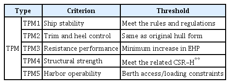
Criteria, thresholds and indicators for TPMs
2.2 Functional analysis and allocation
Each requirement should be functionalized for the new minimal ballast ship design. To functionalize the requirements R1–R5 in Table 4, technologies pertaining to fluid performance are required. R6 and R7 are the requirements related to the structural strength, and R8 requires the ship be able to be adapted to existing harbor facilities. The functions to accommodate each requirement are listed in Table 6, including all the identified requirements.
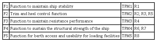
Function list for new non/minimal ballast ship design
2.3 Synthesis
In the synthesis process, the design alternatives shall be generated to implement the functions in Table 6 within the boundaries of the business model. To implement F1 and F4, any requirements for new rules and regulations should be minimized. In addition, the existing rules and regulations for ship stability and structural strength must be satisfied. For F2, a minimum level of the propeller immersion depth and bow draft must be achieved. For F3, any type of external attachment should be avoided to ensure the appropriate ship resistance performance. For F4 and F5, changes in the draft, beam, and bilge radius of the existing ship should be limited to ensure the berth access and usability of cargo loading facilities. The adjustment of the baselines of the bow and stern of a ship can be used to meet the functional requirements. However, when considering the required couplings and machinery systems among the bow, stern, and cargo hold parts of the ship for adjusting the baseline, the design concept shown in Fig. 2 does not meet the ‘revenue’ of the business model.
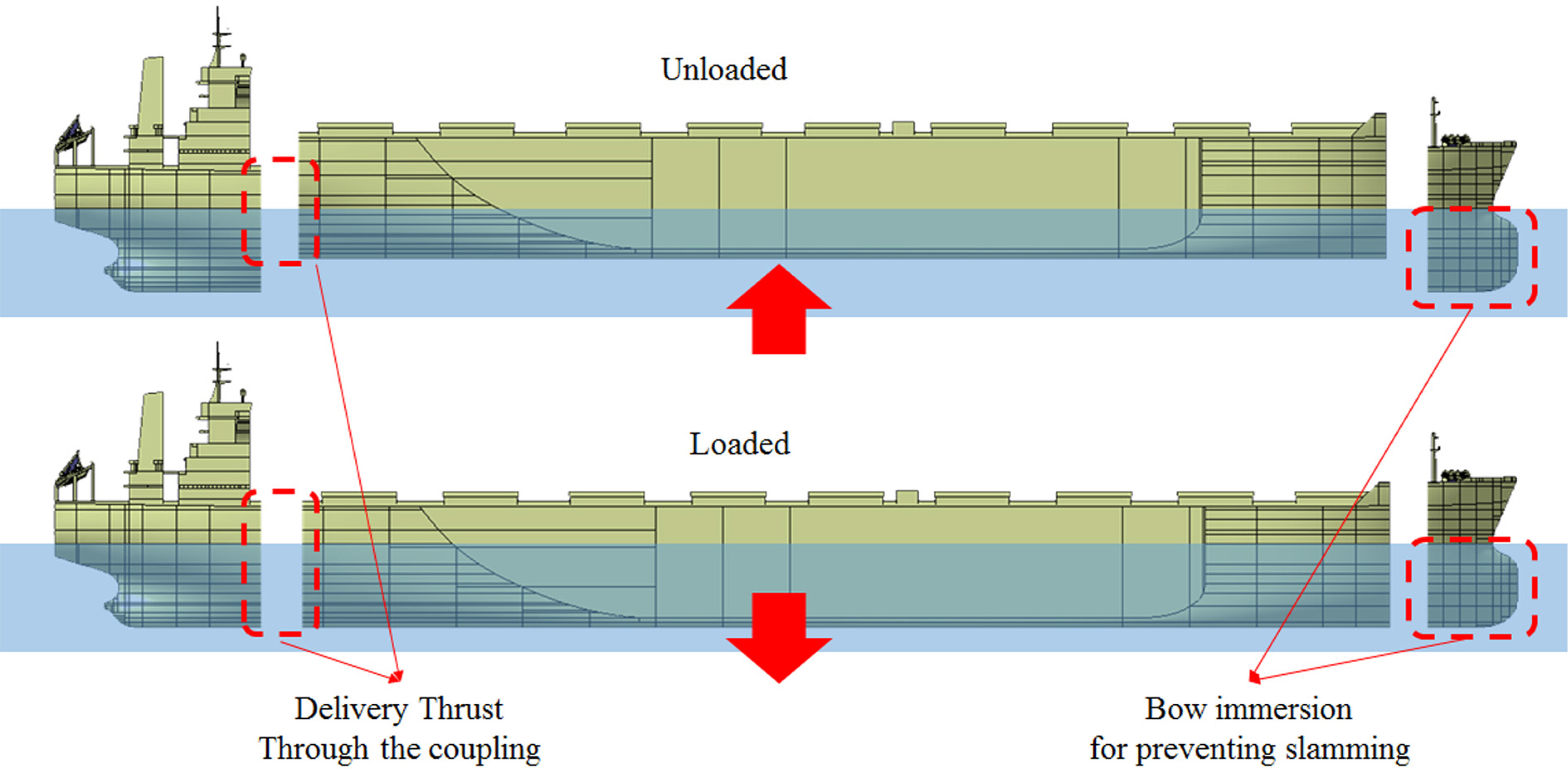
An initial concept of the adjustable bow, stern and cargo hold baselines for non/minimal ballast operation
Since it is practically impossible for an adjustable hull form to meet the requirements of Table 4 and the business model of Table 3, to build a reasonable design alternative for the functions in Table 6, a fixed type uneven baseline hull form (modified) has been generated on the basis of an existing 176K bulk carrier hull form (original). Fig. 3 shows the body plan of an uneven baseline minimal ballast bulk carrier.
Body plan, modified (left side) and original (right side) hull form
From the Fig. 3, the suggested ‘modified’ hull form has uneven baselines of the bow, stern, and cargo holds. These differences should be addressed because an uneven baseline can affect the ship’s resistance performance. In addition, an uneven baseline interferes with the fluid flow and affects the seakeeping ability for F1. Furthermore, measures should be taken to secure the longitudinal strength under repetitive hogging and sagging conditions. To reduce the adverse effects of the shear force and bending moment on the structural strength of the hull, the heel trim must be carefully weighed and controlled during the cargo loading process. For F1 and F4, a center-line bottom keel-based structural reinforcement can be used. While a fin-stabilizer for F1 has no effect on the normal concept of the static stability of a ship, it has a positive effect on the dynamic stability. Since the fin is usually not considered for a large ship, the cost effectiveness and possible capacity of the fin should be considered before implementation. To obtain the proper immersion depth of the propeller of the designed ship, a reduction of the propeller diameter can be considered by changing from a single-screw to twin-screw propulsion with an uneven baseline. In addition, for non-ballast exchange operation in certain loading conditions, a permanent ballast system will be required for F2 and F5. In this case, the operation of the permanent ballast should take the water depth and loading condition control ability of the port into account. The design should also consider the amount of required permanent ballasts for securing the appropriate immersion depth and a safe return voyage with empty cargo holds. By increasing the baseline of the cargo holds, the wetted surface area is decreased slightly, which can contribute to the ship’s resistance performance. However, since the uneven baseline may have a negative effect on the ship resistance performance, the feasibility of design alternatives for F3 should be carefully examined. For F4, in the hull form modification process the applicability of the hull form to the existing rules and regulations is considered.
The provisional specifications of the designed ship are described in Table 7. From the hull form modification of the existing 176K bulk carrier, the wetted surface is reduced by approximately 4.4% compared to those of the original hull form under full loaded conditions. Under ballasting conditions, the required fixed ballast was estimated at approximately 42,000 t for a 7.5 m TA.

Initial dimensions of the designed ship
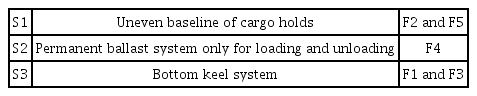
The synthesis results of reviewing the technical alternatives for the required functions are summarized in Table 8. The conceptually designed ship was reconfigured from the existing 176K bulk carrier. The tanks for the ballast are minimized and the auxiliaries and superstructure have been relocated for the initial trim and heel conditions. For S1, the uneven baseline of the cargo holds, consideration should be given to the influence of these differences on the ship’s resistance performance, structural safety, and workability at shipyards. For S2, the amount of permanent ballast should be minimized to consider the controllability of the loading weight distribution. Finally, for S3 the bottom keel should be properly configured to prevent it from detaching from the baseline of the bow and stern.
List of developments for a new non/minimal ballast ship design
3. Ship Resistance Performance basis Feasibility Evaluation
The ship resistance performance affects the operating cost, and especially the fuel oil consumption. For this reason, the ship resistance performance should be determined in the early design phase. Although the model ship basin test is recommended, for a fast and effective evaluation in this study, a computational fluid dynamics (CFD)-based evaluation was adopted with the model ship basin test results and the sea trial data of an existing 176K bulk carrier. Thus, when the evaluation results have economic feasibility, the model ship-based test will be adopted in the next study. For the model scale CFD simulation, a hull model is generated, as described in Table 9.

Geometry and principal particulars of the model ship for CFD
Regarding the ship’s stability performance, the designed uneven baseline hull form has a larger righting arm compared to the original hull form, as shown in Fig. 4.
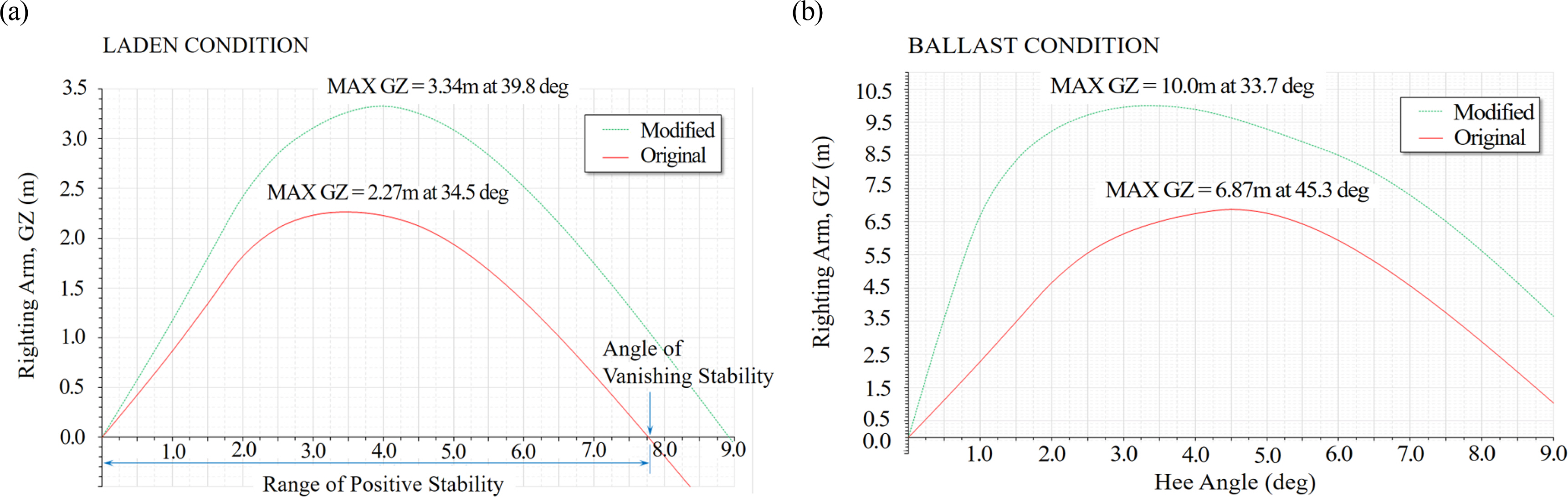
GZ curves of the original and the modified hull form, (a) Laden condition (b) Ballast condition
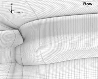
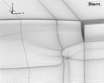
For the model scale CFD simulations, the Reynolds-averaged Navier-Stokes (RANS) equation-based Wave and viscous flow (WAVIS) software which KRISO (Korea Research Institute of Ships and Ocean Engineering) developed and widely used in Korean ship yards was used. As shown in Table 10, understanding the simulation of the flow around the ship helps in generating an accurate grid arrangement. The grid includes the free surface area with a total of 3.6M grid points for the half domain, which is equivalent to the medium size grid in a previous study (Kim et al., 2011). Starting from the initial graphics exchange specification (IGES) description of the ‘original’ and ‘modified’ hull forms, the commercial program GRIDGEN (Pointwise, Inc.) was used to generate the H-O type multiblock structured grid systems. In the CFD simulation in this study, the free surface was captured using the level-set method, while for the turbulence closure, the Explicit algebraic reynolds stress model (EARSM) was used with Launder and Spalding’s wall function. The details of the numerical methods used can be found in Kim et al. (2011), Kim et al. (2014).

Grid information and distribution
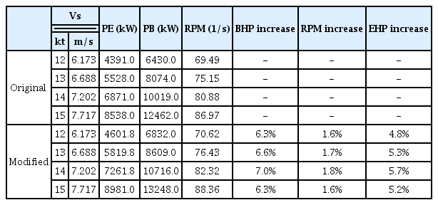
From the numerical resistance test, as shown in Table 11, the effective horsepower (EHP) was predicted to increase from 1.5 to 2.0%, depending on the speed of the bulk carrier, compared to the existing 176K bulk carrier. From the information on the differences between the predicted EHP and the actual instrumented delivery horsepower (DHP) of the existing 176K bulk carrier, the DHP of the designed ship was estimated to have the same ratio for predicting fuel oil consumption as that of the designed ship at the actual scale.

Numerical resistance test results
For more detailed ship resistance performance comparison, model ship basin test has adopted. Fig. 5 shows model ships and Table 12 shows basin test results at same draft (17.7 m) conditions. From the test, EHP increased 5.25% and BHP (Breake horse power) increased 6.55% on average from 12 kt (6.173 m/s) to 15 kt (7.717 m/s) compare to ‘Original’ hull form.
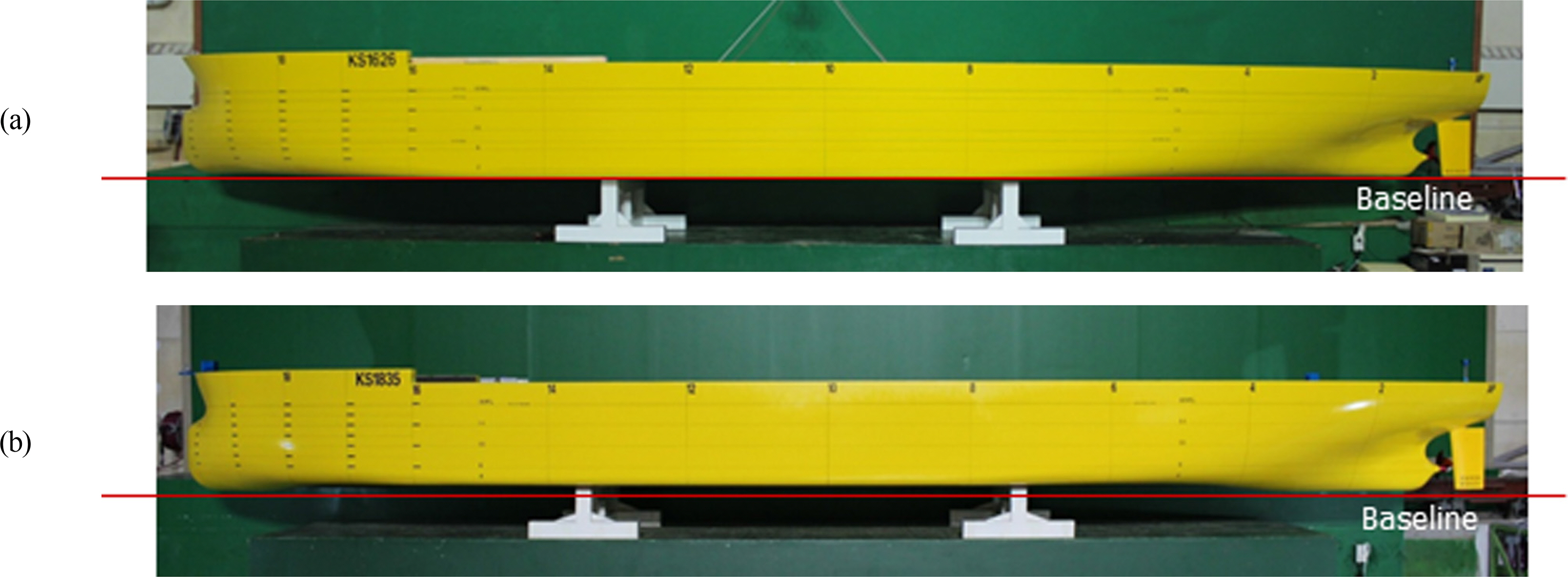
Model ships, (a) original and (b) modified hull form
Model ship basin resistance test results at same draft condition
Empirically, losses in the cargo capacity can be compensated with an enlarged freeboard by considering the bulk general cargo loading condition. Assuming that the modified and original hull form has same cargo amount, the ‘Original’ hull form’s draft can be reduced to 15.89 m when the draft of ‘Modified’ hull form fixed to 17.70 m. At this time, the BHP gap between ‘Modified’ and ‘Original’ hull form increases more than 12.5% as shown in Fig. 6. Fig. 7 shows model ship basin test pictures, conditions and nominal velocity contour at propeller plane at same displacement condition and Fig. 6 shows RPM and BHP of ‘Modified’ and ‘Original’ hull forms.
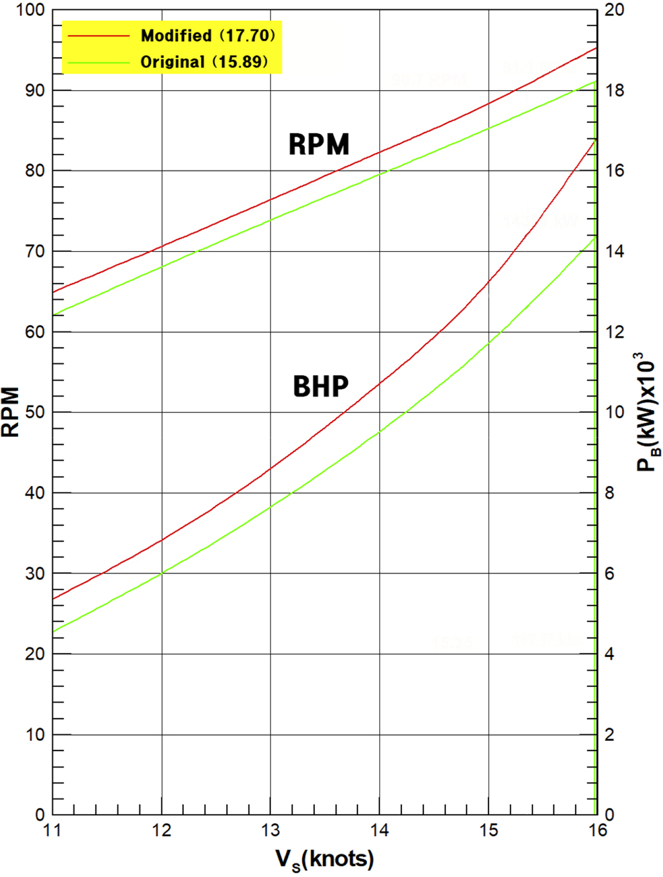
BHP and RPM, (a) original and (b) modified hull form
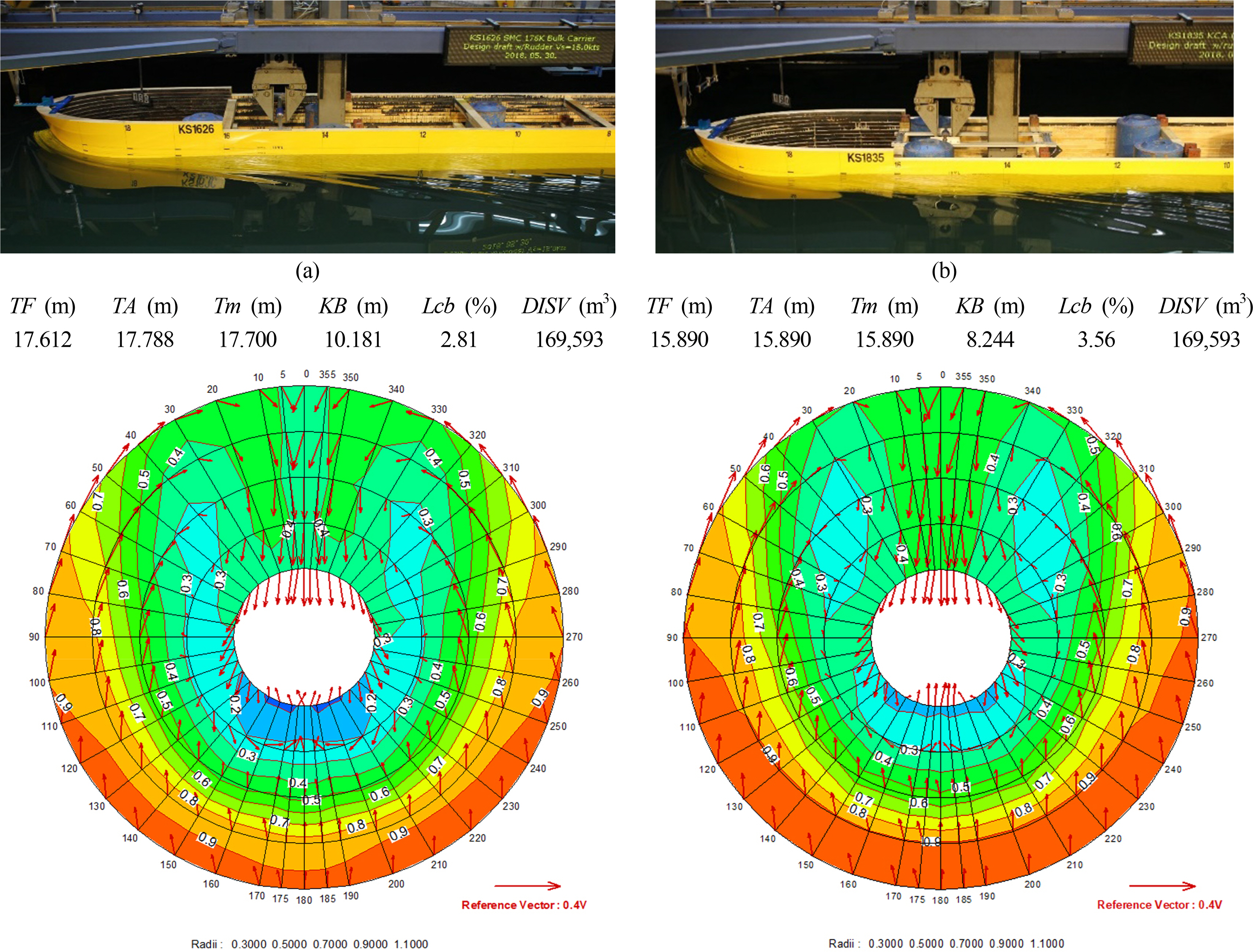
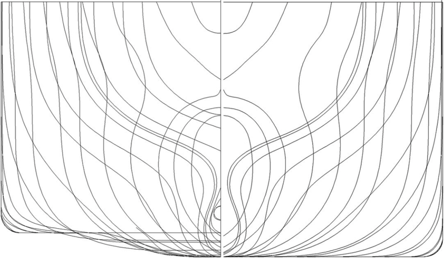
Model ship basin tests (above) and nominal velocity contour at propeller plane (below), (a) original and (b) modified hull form at same displacement condition
To compensate loses in ship resistance performance of ‘modified’ hull form, flow stress intensive parts of hull geometry as shown in Fig. 8 shall be improved. Moreover, enlarged beam width can be considered to increase cargo loading capacity of ‘modified’ hull form.
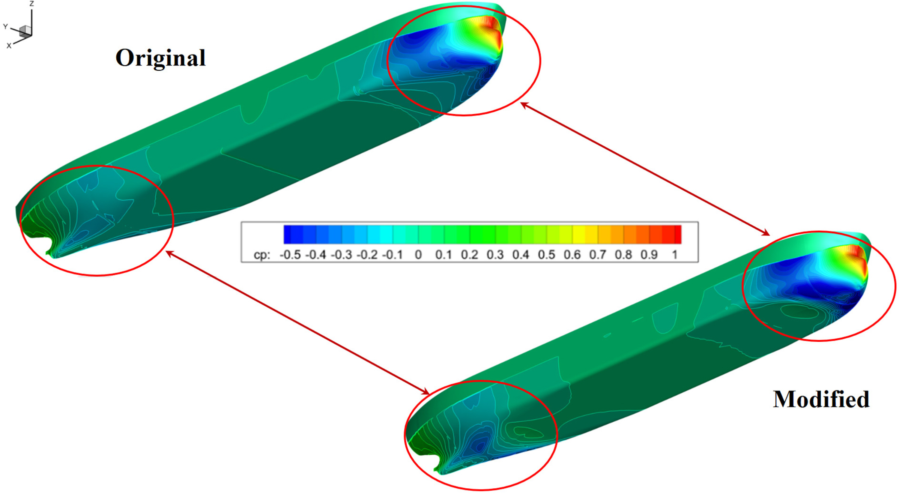
Comparison of the pressure distribution between the original (above) and the modified (below) hull form
Regarding the sea keeping ability, the characteristics of the ship motion in sea waves are important. As shown in Fig. 9, compared to the original hull form, although the modified hull form shows lack of sea keeping performance in heave and roll motion, the pitch motion characteristics of the ‘modified’ hull form do not significantly differ from those of the original hull form. To analyze ship behavior characteristics, SMTP (Ship motion total package), which is the KRISO’s in-house simulation tool (new version of SURVSHIP (Survivability of ship)) has used (Lee, 2015). In the simulation, 0.02 second time step has applied. Figure 6 shows ship behavior characteristics in the regular wave with beam-sea (entrance angle of 90 degree) condition. Due to uneven baseline, suggested hull form shows lack of seakeeping ability especially in heave and roll motions. In case of Heave motion, it is estimated that waves between bow and stern uneven baseline enlarges ship motion compare to ‘original’ hull form. For roll motion, it is estimated that shorten immersion depth of ‘modified’ hull form enlarges initial roll motion.
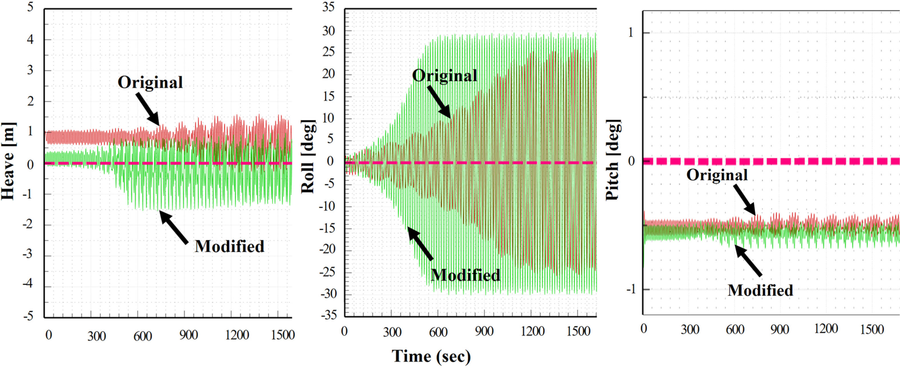
Sample of the designed ship’s motion analysis results in waves under fully loaded conditions (wave height: 2 m, beam sea condition)
To compensate for the losses in the ship motion under waves, relationship between the geometry of mid-ship section and roll damping will be considered (Park et al., 2019). If the propeller diameter is decreased to accommodate for the adjusted ship speed and the engine performance, then the elevating height of the baseline of the cargo holds can be decreased to secure the proper cargo capacity, ship resistance, and seakeeping performance. When considering only the mid-ship section of the suggested uneven baseline minimal ballast bulk carrier, a decrease in the depth of the cargo holds will lead to a decrease in the ultimate bending moment capacity. To compensate for the decreased ultimate bending moment capacity, the weight of the ship’s structure can be increased. For this reason, in order to convince the technical feasibility of the suggested uneven baseline minimal ballast bulk carrier, the structural design evaluation under different sea states should be adopted in the next study.
4. Conclusion
To design a new minimal ballast ship which operate certain amount of permanent ballast for ballast-water free operation, the existing alternatives for ballast water were reviewed. To overcome the lack of berth access and loading constraints of the MIBS / NOBS ‘storm ballast’, the conceptually an uneven baseline basis ‘no or minimal discharge’ alternative so called ‘modified’ hull form suggested. To generate the ‘modified’ concept, a simplified systems engineering-based design approach was adopted. By examining the roles of the ballast water and existing alternatives, seven general requirements for a new minimal ballast ship and one specific requirement for overcoming the penalties of a ‘storm ballast’ were identified. Then, five functional requirements were generated for the uneven baseline minimal ballast vessel. As suggested, the concept has wide and parallel sides compared to the existing V-hull design of a ‘storm ballast’, so the lack of berth access capability can be compensated theoretically. As for loading constraints, the smaller beam size of the suggested concept compare to exiting MIBS / NOBS concept can be helpful in compensating for the load constraints. However, during the model ship basin test, under the same draft conditions, the EHP of ‘modified’ increased 5.25% and BHP increased 6.55% on average compare to ‘original’ hull form. Given the loss in cargo loading capacity, the suggested ‘modified’ hull form’s economic feasibility is assessed at an awkward level. So, resistance performance at same displacement condition has also tested via model ship basin test. From the basin test, more than 12.5 loss in BHP has convinced. From this review result, losses in the cargo capacity and ship resistance performance shall be consider concurrently in the design phase to have technical and economic feasibility. By optimizing the geometry and dimension of the ‘modified’ hull form, a certain amount of loss in resistance performance and cargo capacity shall be compensated in the next study. Although the suggested uneven baseline basis ‘modified’ hull form has many rooms for commercializing, the suggested design, evaluation process and methodologies can be adapted to generate various attempts at developing non/minimal ballast ships to keep the healthy ocean environment from organisms of different ecosystems or a large amount of sterile sea water.
Abbreviations
AUBAFLOW
automatic ballast flow
BW
ballast water
BWE
ballast water exchange
BWM
ballast water management
BWTS
ballast water treatment system
CFD
computational fluid dynamics
CSR-H
harmonized common structural rules
Cf
friction resistance coefficient
Cp
prismatic coefficient
Ctm
total resistance coefficient of model-scale ship
Cfm
Cf of model-scale ship
Cfs
Cf of full-scale ship
Cr
residuary resistance coefficient
Cts
total resistance coefficient of full-scale ship
D-1
regulation about ballast water exchange
D-2
regulation about ballast water treatment
DHP
delivery horsepower
DISV
displacement volume
DWT
deadweight tonnage
EARSM
explicit algebraic Reynolds stress model
EHP
effective horsepower
FOC
fuel oil consumption
IGES
initial graphics exchange specification
ISO/IEC
international organization for standardization/ international electro-technical commission
KPPs
key performance parameters
KB
vertical distance between the keel and the center of buoyancy
MIBS
minimal ballast water ship
MOE
measure of effectiveness
MOP
measure of performance
NOBS
non-ballast water ship
RANS
Reynolds-averaged Navier-Stokes
TA
trim aft
TF
trim forward
Tm
mean draft at a midships
TPMs
technical Performance measures
WAVIS
wave and viscous flow (proprietary brands)
VLCC
very large crude oil carrier
ULCC
ultra large crude oil carrier
Acknowledgements
The initial concept of an ‘uneven baseline minimal ballast water bulk carrier’ was introduced as a proceeding at the 17th International Congress on Maritime Transportation and Harvesting of Sea Resources (IMAM) (Kang et al., 2017) and concretized in this study. This research was supported by a grant from the National R&D Project of KRISO research project PES3000.
Notes
Author name ORCID Contributions
Kang, Hee Jin 0000-0002-8241-3751 ①④⑤
Kim, Kwang-Soo 0000-0001-7548-7157 ③
Choi, Jin 0000-0001-9842-2049 ③
Lee, Yeong-Yeon 0000-0002-0408-6222 ②
Ahn, Haeseong 0000-0001-6330-3744 ⑤
Yim, Geun-Tae 0000-0002-5382-8931 ②
① Conceived of the presented idea or developed the theory
② Carried out the experiment or collected the data
③ Performed the analytic calculations or numerical simulations
④ Wrote the manuscript
⑤ Supervised the findings of this study