J. Ocean Eng. Technol. Search

CLOSE


J. Ocean Eng. Technol. > Volume 35(6); 2021 > Article
Park and Choi: Greenhouse Gas Emission Analysis by LNG Fuel Tank Size through Life Cycle

Abstract

As greenhouse gas emissions from maritime transport are increasing, the International Maritime Organization is continuously working to strengthen emission regulations. Liquefied natural gas (LNG) fuel is less advantageous as a point of CO2 reduction due to the methane leakage that occurs during the bunkering and operation of marine engines. In this study, greenhouse gas emissions from an LNG-fueled ship were analyzed from the perspective of the life cycle. The amount ofmethane emission during the bunkering and operation procedures with various boil-off gas (BOG) treatment methods and gas engine specifications was analyzed by dynamic simulation. The results were also compared with those of other liquid fuel engines. As a result, small LNG-fueled ships without a BOG treatment facility emitted 32% more greenhouse gas than ships utilizing marine gas oil or heavy fuel oil. To achieve a greenhouse gas reduction via a BOG treatment method, a gas combustion unit or re-liquefaction system must be mounted, which results in a greenhouse gas reduction effect of about 25% and 30%. As a result of comparing the amount of greenhouse gas generated according to the BOG treatment method used with each tank size from the perspective of the operating cycle with the amounts from using existing marine fuels, the BOG treatment method showed superior effects of greenhouse gas reduction.

1. Introduction

With global economic growth, the number of cargo ships required for maritime transportation has increased, resulting in a larger problem of greenhouse gas (GHG) emissions. As the maritime transport sector has become a significant contributor to global GHG emissions, the International Maritime Organization, which is responsible for environmental regulations, has made continuous efforts to reduce GHG emissions from ships (Wada et al., 2021). The Marine Environment Protection Committee (MEPC) has reviewed the emission regulations, including the Energy Efficiency Design Index (EEDI), Energy Efficiency Operating Indicator (EEOI), Energy Efficiency Existing-ship Index (EEXI), Energy Efficiency Performance Indicator (EEPI), and Ship Energy Efficiency Management Plan (SEEMP), and also simultaneously discussed the environmentally friendly frameworks for cargo ships (Ahn et al., 2021).
Liquefied natural gas (LNG) is an environmentally friendly fuel with the unique benefit of reducing CO2 emissions by 10–20% (Lee et al., 2020). However, the use of LNG as a ship fuel necessitates the process of bunkering, and treatment of boil-off gas (BOG) during bunkering is essential. The currently available BOG treatment methods are venting, use of a gas combustion unit (GCU), and re-liquefaction.
However, BOG treatment or the transport of LNG as an environmentally friendly fuel entails increased methane emissions, although the emissions of conventional pollutants such as NOx and SOx are reduced (Yu et al., 2020). Compared to CO2, methane leads to an approximately 25-fold higher GHG effect due to its high global warming potential (GWP) (Jang et al., 2021). Despite efforts to minimize the release of methane into the atmosphere, the following scenarios of potential leakage are possible (Herdzik, 2018).
  1. Pipeline leakage upon connection or separation during the LNG loading/unloading operations

  2. Leakage from the LNG tank during BOG removal

  3. Leakage through the liquefaction system in operation during loading or sailing

  4. Leakage during the gas-freeing operation inside the LNG tank

  5. Leakage during LNG bunkering

  6. Leakage by incomplete combustion when dual fueling or using LNG as fuel

Therefore, the methane emission throughout the entire LNG supply network or the ship engine exhaust gas offsets the benefits of using LNG and makes LNG a less desirable alternative to marine gas oil (MGO). In other words, the advantages of LNG as an environmentally friendly fuel are reduced (Edfors and Bremberg, 2021). Therefore, it is important to compare the use of LNG fuel with the use of conventional marine fuels in terms of GHG emissions (Winnes and Fridell, 2009). Moreover, the effects of emissions related to marine fuel processing, its GHG emissions, and their correlations should be examined.
From the perspective of the LNG-fueled ships, this study considered the integration of bunkering and operation processes and identified the environmental indicators using for making comparisons with conventional fuels. Indicators for comparison between different fuels need to be provided to enable ship owners and operators to determine potentials on demand. If the perspective is extended to include ship bunkering and operation, the results are likely to be more complex than other conventional results, i.e., follow-up studies with a wider scope and case studies may be required.
Numerous studies have investigated the gases directly emitted by ships. Chang et al. (2013) estimated the GHG emissions by ship type based on the data of the ships treated at ports, taking an approach relying on the characteristics of individual ships. Styhre et al. (2017) analyzed the level of GHG emissions for ships at ports based on annual port data. They also presented the results of dynamic modelling in addition to the actual field measurements. Shao et al. (2018) simulated the influence of temperature variation in the bunkering of LNG-fueled ships on the production of BOG. Shao et al. (2019) used dynamic simulation to identify the optimum ship-to-ship bunkering time and provided a reference guideline of bunkering to minimize BOG production. Lee et al. (2020) performed dynamic simulation to estimate the collected amount of BOG produced during ship-to-ship LNG bunkering and assessed the contribution of each parameter, including temperature variation, transportation rate, and pipe insulation performance. By combining the approaches of the two previously described studies, several simulations and cycle assessments have been conducted to suggest useful environmental indicators. Ryste (2012) applied the screening life cycle assessment (LCA) technique to determine the range of the LNG life cycle and establish the LNG value chain in the interpretation of climate change and related environmental issues. El-Houjeiri et al. (2019) applied the LCA approach to conduct an environmental assessment of the liquefaction, transportation, and re-liquefaction of LNG. Beyond ships, Arteconi et al. (2010) used the LCA approach in an investigation of trailers on land to make a life cycle comparison from the aspects of GHG emissions from diesel and LNG engines.
Nevertheless, there is a general paucity of studies on the long-term assessment of measures for reducing GHG emissions. The prediction of GHG emissions mandates prediction, from operational perspectives, beginning from the preparation stage of fuel use. Thus, indicators are required to determine whether LNG ship fuel is a practical solution in comparison with other fuels from environmental perspectives that complies with emission regulations.
Taking the aforementioned factors into consideration, this study investigated the GHG emissions from methane leakage during bunkering, the GHG emissions associated with the BOG treatment method, and the GHG emissions associated with engine use. The bunkering and operation processes of LNG-fueled ships were integrated so that environmental indicators of GHG emissions could be recommended for the entire life cycle depending on the size of the fuel tank. The results showed that the contribution varies according to fuel tank size, which distinguishes this study from previous studies as more specific conditions were used in this study to describe the GHG emissions that affect the environment from the perspective of ship operation.

2. Simulation Method

2.1 Determination of LNG Bunkering

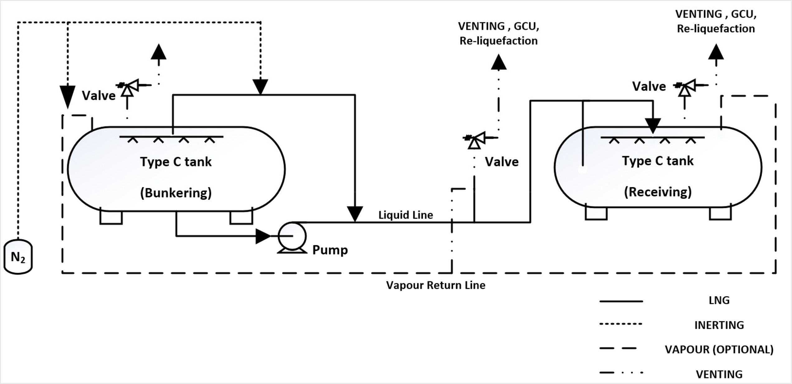
Fig. 1 shows an overview of the process for the LNG bunkering scenario. The system consists of two LNG storage tanks (bunkering and receiving), an LNG pump, the bunkering pipeline, and the BOG pipeline (Jeong et al., 2017). The LNG pump transports the LNG loaded in the bunkering tank to the receiving tank. The pump as a transportation device is advantageous because it reduces LNG transport time (Sharafian et al., 2019). Safety valves are attached to prevent overpressure in the LNG tank, and the corresponding line leads to emission or treatment according to the BOG treatment method.

2.2 Tank Geometry

The fuel tanks eligible for LNG-fueled ships are listed in the International Gas Carrier (IGC) code and the International Code of Safety for Using Gases or Other Low-Flash-Point Fuels (IGF) code. In general, the Type C tank is used. The Type C tank has a maximum allowable working pressure (MAWP) of 700 kPa or higher and is thus regarded as a pressure container (Chorowski et al., 2015). The capacity of the bunkering tank is 500 m3. The two receiving tanks may have different capacities of 500 m3 and 1,000 m3 (Kwak et al., 2018; Jung et al., 2018). Prior to bunkering, the levels of the bunkering tank and the receiving tank are 98% and 10%, respectively. The initial pressure in the bunkering tank is 300 kPa, and the initial temperature is −146.4°C. The pressure and temperature in the receiving tank are 101 kPa and − 162.1°C.
The LNG inside the tank is stored at a very low temperature (approximately −160°C) and pressure (100–1,000 kPa). The main components of the LNG in the bunkering and receiving tanks are methane and light hydrocarbons (mainly C1–C4 hydrocarbons) in a mixture with N2, as presented in Table 1 (Noh et al., 2014).

2.3 LNG Bunkering Pipeline

The LNG transport line connecting the bunkering tank and the receiving tank consists of the liquid line, the vapour return line, and the N2 line. In the liquid line, transport is mediated through a loading arm or flexible hose (Wood and Kulitsa, 2018). The transport line is often connected to the quick-connect coupling (QC)/disconnect coupling (DC) and the emergency release coupling (ERC) to allow hose separation in an emergency. In addition, to prevent a loss of LNG, each separate section contains a disconnection valve for automatic shutdown. With the exception of the aforementioned devices, the transport line leads the flow of LNG through the pipeline, and the simulation considerate the flow velocity to prevent any additional surge pressure due to friction or cavitation (Lee et al., 2020). The single material of the pipe for transporting cryogenic LNG is stainless steel. The details are presented in Table 2 (Sharafian et al., 2019).

2.4 Greenhouse Gas (GHG) Emission by LNG Bunkering Procedure

For LNG bunkering operation, a detailed manual containing the operation procedures, safety and emergency protocols, and maintenance requirements should be provided. The manual should contain the procedures for inerting, gassing up, cooling down, pumping LNG, LNG spraying, vapour return management, draining, purging, and disconnecting, in addition to the validation and risk assessment procedures (Vairo et al., 2020). The procedure in this study was applied based on certain simplified steps of the aforementioned procedures and of the bunkering process suggested in the 2018 guideline of the European Maritime Safety Agency (EMSA). Table 3 describes the steps. The gas emission was interpreted for the loading, line purging, and operating of the IMP Type C tank.
For the loading in Step 1, transport to the receiving tank is performed, and heat ingress occurs due to the temperature difference of the external walls of the tank. The heat ingress through the tank wall causes the production of BOG and increases the tank pressure (Zincir and Dere, 2015). The BOG should be treated appropriately but difficulties exist. Venting, with the advantage of simple release to the atmosphere, could cause problems such as LNG fuel loss, environmental pollution, and increased risks of fire and explosion. Most LNG-fueled ships with the Type C tank lack the addition of a GCU as they are designed based on the concept of maintaining the pressure rise caused by heat ingress. The treatment of BOG using a GCU is problematic from an environmental perspective because the gas from the combustion is released to the atmosphere (Ryu et al., 2016). Moreover, ship owners may be reluctant to perform reliquefaction, which demands extra space and an initial investment cost.
Data pertaining to CO2 emission in the BOG treatment in LNG bunkering are insufficient, and the GHG effect is likely to be underestimated. In this study, the level of CO2 emission according to the BOG treatment method was established through simulation. Venting releases BOG to the atmosphere to control the internal pressure of the tank. In reference to the guideline of the Intergovernmental Panel on Climate Change (IPCC), the 100-year GWP of CH4 (the main component of BOG) is 25, indicating a 25-fold higher GHG effect than CO2 (Penteado et al., 2012). The GWP indicates the global warming effect of a given GHG in comparison to the effect of CO2 (Unseki, 2013). For consideration of venting, the GWP was converted to EmissionCO2 (kg) using Eq. (1):
(1)
EmissionCO2=GWPCH4mCH4
where GWPCH4 is 25 in 100 years, and mCH4 is the content (kg) of CH4 in BOG.
In the case of a GCU, the gases are released to the atmosphere through complete combustion (CH4 + 2O2 → CO2 + 2H2O) to prevent immediate emission of the GHG. For 1 mole of reactant CH4, 1 mole of product CO2 is produced (Dissanayake et al., 1991). The conversion to EmissionCO2 (kg) according to Eq. (2) assumes complete combustion by the GCU:
(2)
EmissionCO2=nCO2nCH4MCO2
where nCO2 is the number of moles of CO2 (mol), nCH4 is the number of moles of CH4 (mol), and MCO2 is the molecular mass of CO2 (44.01 g/mol).
In the case of re-liquefaction, a technique to liquefy BOG for storage in the cargo tank, the N2 cycle is used. The devices required for re-liquefaction are a power-supplied compressor, expander, and heat exchanger. The operation of these devices demands a power supply, and a certain amount of CO2 is produced in the generation of the electricity. The amount of CO2 produced in generating the power required by BOG re-liquefaction was calculated according to Eq. (3):
(3)
EmissionCO2=EFelectricSPCN2CyclemBOG
where SPCN2 Cycle is the power consumption in using the N2 cycle as the refrigerant cycle (1.44 kWh/kgBOG), mBOG is the mass of BOG (kg) (Kwak et al., 2018), and EEelectric is the CO2 emission index (0.466 kg CO2/kWh) (Im et al., 2020).
In Step 2 of the procedure, line purging is the process that follows loading to the receiving tank. The pipe used for LNG loading should be detached from the system at the end of the operation. To remove residual LNG before detaching the pipe, substitution using inert gas is performed. The purging process is necessary for the safe removal of residual LNG, which is flammable and explosive. The release of LNG or NG from the pipe during this process has an effect on the GHG problem. Lowell et al. (2013) stated that there is no effective way to eliminate the methane leakage that occurs during the process, and a loss of approximately 0.03% occurs according to calculation based on the methane inside the tank. This methane can act as a powerful GHG. This study performed conversion according to Eq. (4):
(4)
EmissionCO2=mCH4ρLNGGWPCH4
where mCH4 and ρLNG are the mass of CH4 inside the tank and the density of the loaded LNG, respectively, and GWPCH4 is 25 in 100 years.
In Step 3, the operating process is the sailing of the LNG-fueled ship, which is equipped with a dual-fuel engine. Despite the use of environmentally friendly fuels, the engine EmissionCO2 (kg) as a result of fuel consumption. The CO2 emission for this step can be estimated using Eq. (5):
(5)
EmissionCO2=EFEnginePenginetoperating
where Pengine is the output of the engine (kW), toperating is the time (h) of sailing of the ship using the fuel loaded in the tank, and EFengine is an indicator of the CO2 emission (g/kWh) for the respective engine.
BOG, which leads to the GHG effect, results from the combination of the following causes. In bunkering, CO2 is produced in each procedure due to such varied causes as the heat ingress of the tank and other devices and water level fluctuation. In this study, a dynamic model was developed to analyze the influences of the causes in each procedure according to the amount and composition of the BOG. The GHG effect was estimated after conversion to the equivalent CO2 emission.

3. Dynamic Simulation

3.1 Aspen Hysys Simulation of LNG Bunkering

Aspen Hysys is a chemical process simulator used in the mathematical modelling of a complete chemical process in unit operation. Hysys allows numerous core calculations of chemical engineering, including mass balance, energy balance, vapour–liquid equilibrium, heat transfer, mass transfer, mass fraction, and pressure drop (Naji et al., 2019). The thermodynamic interpretation of the process was based on the Peng–Robinson state Eqs. (6)(11), which are known to lead to relatively accurate analyses of the thermodynamic properties of hydrocarbons, including LNG (Lee, 2017):
(6)
P=RTVm-b-aαVm(Vm+b)+b(Vm-b)
where the parameters a, α, b, and ω are defined as follows:
(7)
a=0.45724R2Tc2Pc
(8)
b=0.07780RTcPc
(9)
α=[1+k(1-Tr0.5)]2
(10)
k=0.37464+1.54226ω-0.26992ω2
(11)
Tr=TTc
where P is pressure, T is temperature, R is the gas constant, and Vm is the mole volume. a and b indicate the energy parameter and the size parameter as a function of the critical temperature and pressure

3.2 LNG Bunkering Input Preparation

For LNG stored as a cryogenic liquid, heat ingress continuously induces BOG (Ryu et al., 2016). To incorporate the increase in vapour pressure inside the tank due to BOG in the modelling, the heat ingress was modeled using Eqs. (12) and (13) (Al-Breiki and Bicer, 2020). For dynamic simulation of the fuel tank, the tank model was constructed in consideration of the heat volume according to the water level (Cadafalch et al., 2015):
(12)
Q1=UAtank(Tambient-Ttank)
(13)
Q2=Tank levelTankpresentlevelQ1
where Q1 and Q2 are heat ingress (kJ/s), U is the total heat transfer coefficient of each tank (W/m2·°C), A is the area of tank (m2), and TRIANGLET is the difference between the surrounding temperature and the internal temperature of the tank (°C). Eq. (13) reflects the increase in heat ingress caused by the increase in the water level of the receiving tank, with 98% as the reference, while real-time changes are taken into account.
The causes of BOG include the increased water level in the tank, the heat ingress due to the input device, and the heat ingress through the pipe from the surrounding environment. The heat ingress due to the water level as the tank is being filled and the heat ingress through the pipe are reflected in Eq. (14):
(14)
Q3=UApipe(Tambient-Tpipe_in)
where Q3 is the heat ingress (kJ/s), U is the total heat transfer coefficient of the transport pipeline (W/m2·°C), A is the area of pipe (m2), and TRIANGLET is the difference between the surrounding temperature and the internal temperature of the pipe (°C).
The pump used to transport the LNG increases the pressure, and the mechanical energy transferred from the pump shaft is partially lost in the form of heat. The pressure conversion leads to heat ingress, as reflected in Eq. (15) (Lee et al., 2020).
(15)
Q4=W˙actual-W˙ideal=(1-η)m˙(hout-hin)pump
In the equation, Q4 is the heat ingress (kJ/s), is the mass flow (kg/s), (houthin)pump is the specific enthalpy (kJ/kg), and η indicates the efficiency of the pump. The heat ingress is incorporated as follows. The previously described Q2, Q3, and Q4 correspond to the heat ingress that induces BOG, and these factors combine to have an effect on the BOG, which ultimately leads to the GHG effect. To transport the LNG, a pump, as a pressure increasing device, is used, and power is consumed as the cryogenic LNG is transported to the tank. As mentioned previously, a certain amount of CO2 is produced through the power generation, and the required power supply causes GHG emission. The CO2 emission via heat ingress of the pump is reflected in Eq. (16):
(16)
EmissionCO2=PpumptoperatingElectricEmissionFactor
where Ppump is the power consumed (kW), toperating is the pump operation time (h), and Electric Emission Factor is the CO2 emission index per generated power (0.466 kgCO2/kWh) (Im et al., 2020).

4. Result

4.1 LNG Bunkering CO2 Emission

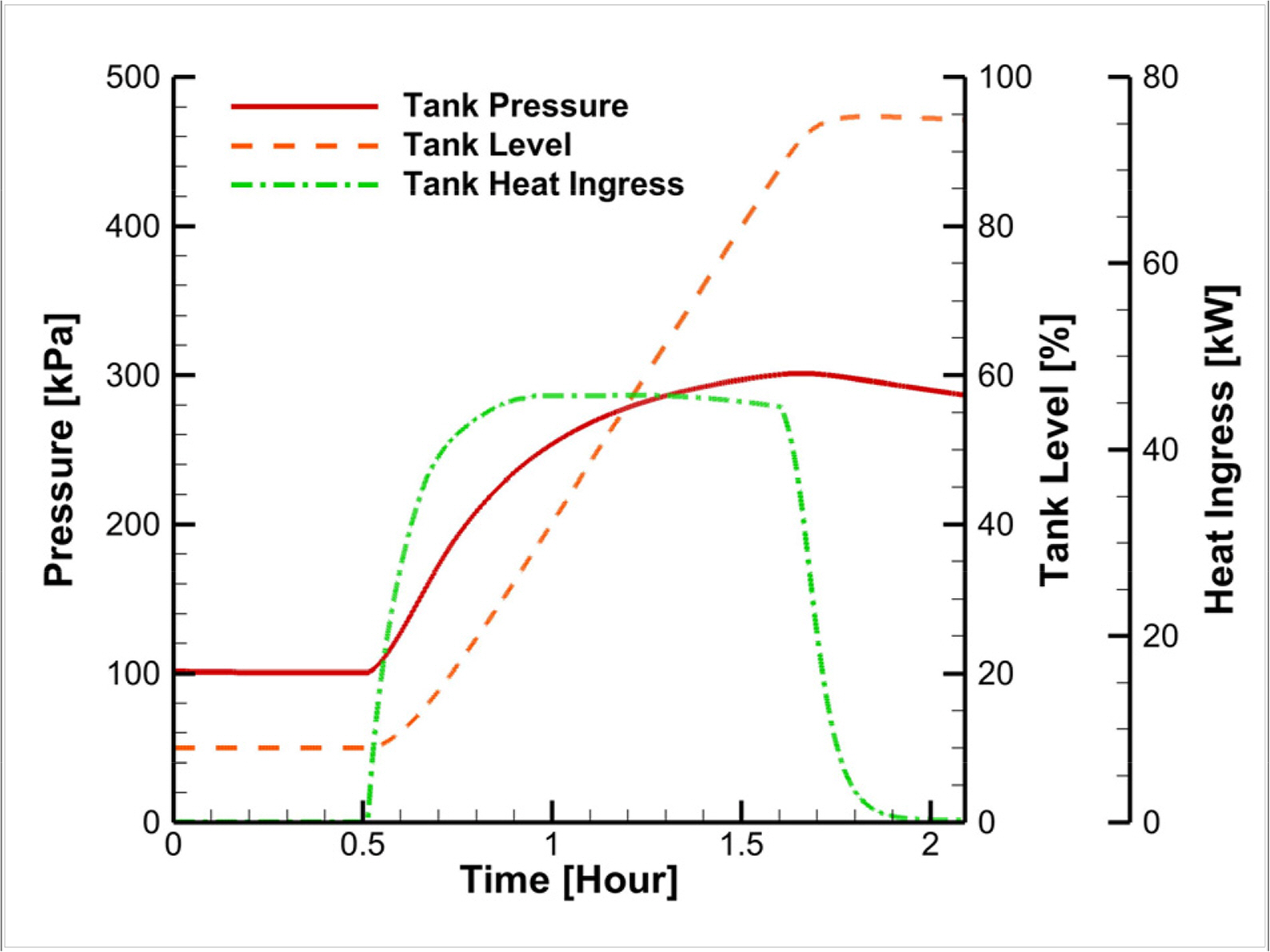
Fig. 2 shows the properties of the tank with time through the bunkering process based on a receiving tank size of 500 m3. The increases in water level and pressure accompanying the loading of LNG are apparent. The increased water level of the tank, pressure increasing device, and piping that induce heat ingress cause the overall heat ingress to increase.
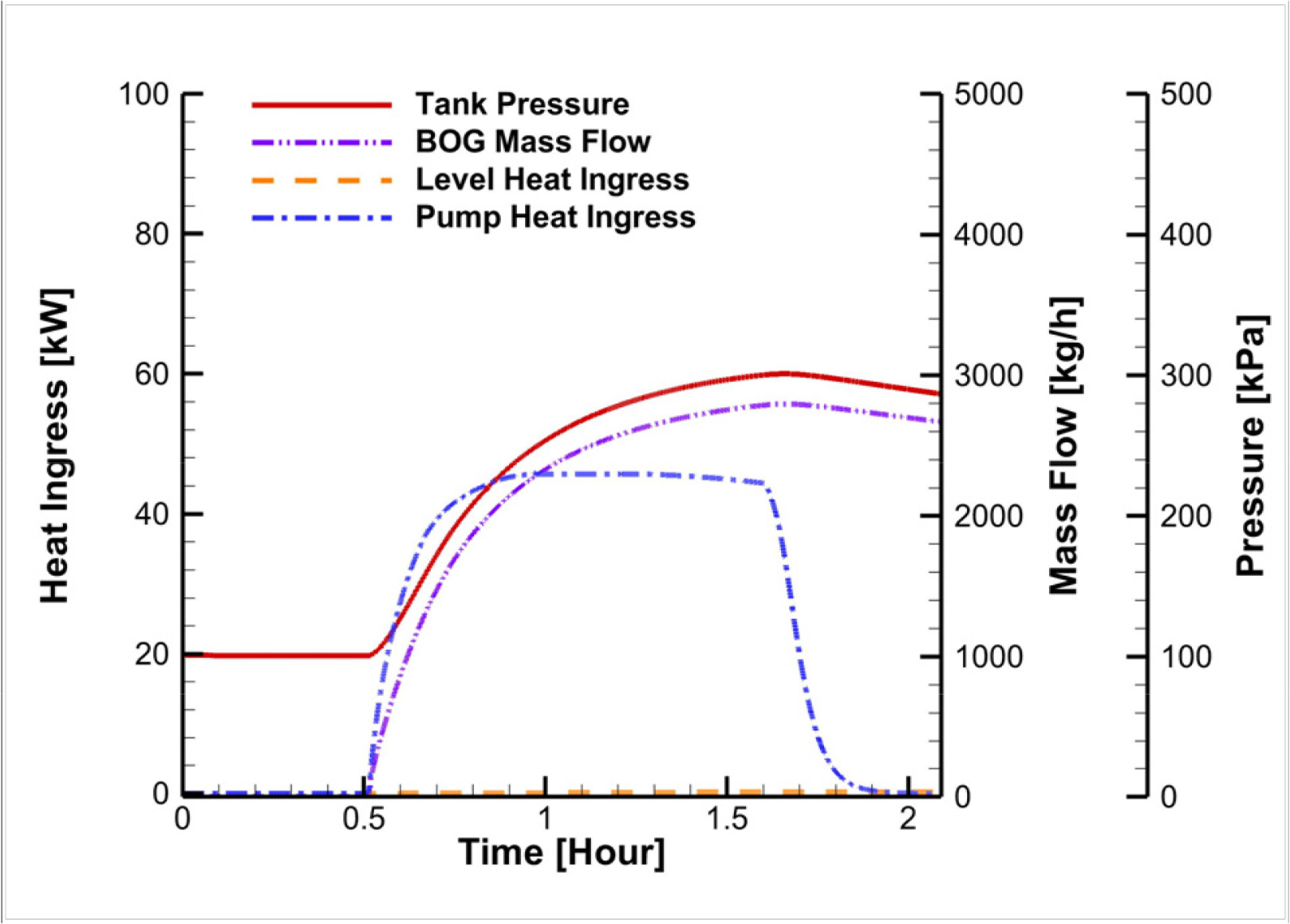
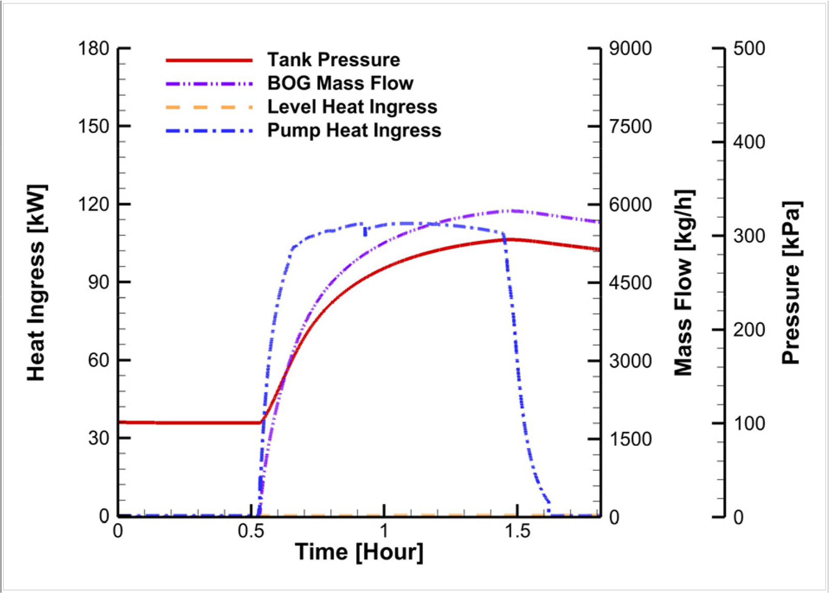
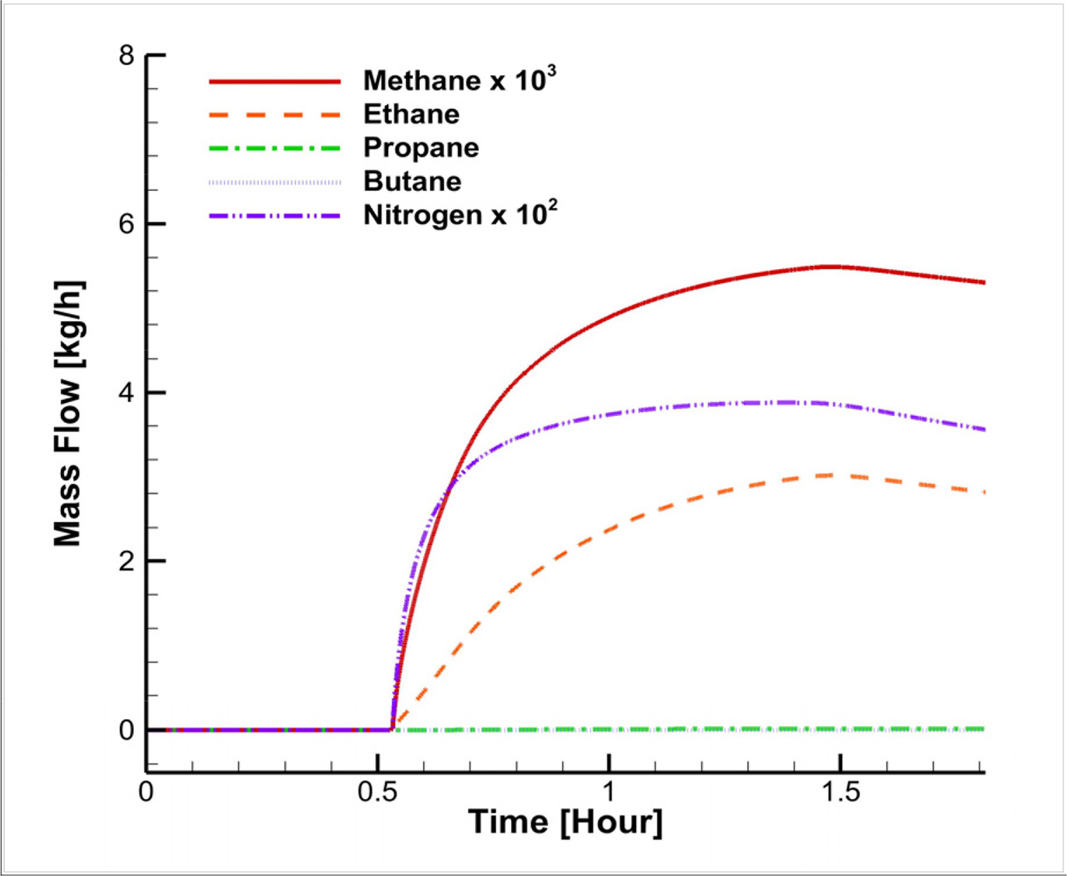
Fig. 3 shows the pressure, heat ingress, and BOG flow according to time during bunkering. As bunkering progresses, the water level of the tank increases, resulting in an increase in the heat ingress related to the transport device and the heat ingress related to the increased water level. The production of BOG attributable to heat ingress thus increases the level of BOG, along with an increase in the internal pressure of the tank. If BOG treatment is not available during the loading of LNG to the receiving tank, the continuous increase in heat ingress leads to a continuous increase in tank pressure. Unless the pressure is controlled, the design pressure is reached, causing the safety valve to operate, which leads to even more production of GHG. For these reasons, treatment of the BOG is essential. Fig. 4 shows the changes with time of the BOG components in the receiving tank that require treatment.
Table 4 presents the mass of the BOG components that should be treated to prevent a pressure rise in the receiving tank. The BOG composition in Table 4 differs from the LNG composition in Table 2. The main component is methane, so it may be safely conjectured that the BOG produced during bunkering is pure methane. The three major ways to treat BOG and the corresponding CO2 conversion of each BOG treatment are shown in Table 5. The method of venting with its atmospheric release causes the highest GHG emission.
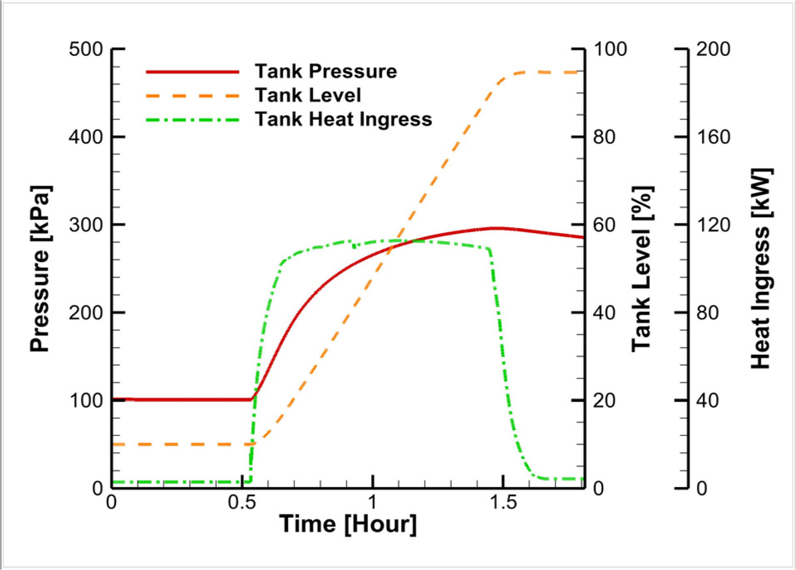
Fig. 5 shows the changes in pressure, water level, and heat ingress in the 1,000 m3 receiving tank through time. At the beginning of bunkering, the inflow of cryogenic LNG and the heat ingress due to the compressor device lead to an increase in overall heat ingress. The pressure and water level also show a trend of increase.
As shown in Fig. 6, the heat ingress values related to the water level and the compressor device and the BOG flow increase with time. The transported flow increases with operation of the pump, which in turn increases the pump heat ingress, and the consequent rise in water level increases the level-related heat ingress. It is also apparent that the amount of BOG to be treated increases with the resulting increase in tank pressure. Fig. 7 shows the amount of BOG to be treated according to time for the receiving tank. Methane, the most abundant component, requires the highest level of treatment, and the amount of methane to be treated increases as the volume increases.
The amount of methane to be treated for the receiving tank in LNG bunkering is approximately 6,000 kg, as shown in Table 6. The content of methane is the highest content among the BOG components, and it is even higher in comparison to the LNG composition. This allows the assumption that the BOG is composed entirely of methane. As methane is the main GHG, its treatment is indispensable. Table 7 presents the result of quantifying the CO2 emission in accordance with each BOG treatment method. Compared to venting, GCU and re-liquefaction, which release CO2 through combustion, are more advantageous, reducing the GHG at a rate of 50% or higher.

4.2 LNG Line Purging

Ships using LNG as fuel emit a large amount of GHG during the line purging process for disconnecting the bunkering line, as well as in bunkering. After a 98% filling of the receiving tanks, line purging is performed, and methane and CO2 are released, as shown in Table 8.

4.3 Operating

The engine selected for the LNG-fueled ship was the Hyundai 5H22CFP, which is a dual-fuel engine. The GHG emission for the ship’s fuel consumption based on the fuel type is as follows: 630 g CO2e/kWh for MGO, 620 g CO2e/kWh for heavy fuel oil (HFO), and 412 g CO2e/kWh for LNG (El-Houjeiri, Hassan et al., 2019; Jang et al., 2021). The CO2 emission varied according to the tank size and the BOG treatment method, as shown in Table 9. The fuel consumption is the amount of fuel required by the selected engine to the consumption at which a trace amount of LNG remains inside the tank (heel), i.e., 10% from the 98% filling of the receiving tank. The operation time per tank size can be estimated based on the engine use. When the tank size is larger, the sailing time is larger, which is a benefit from the operational perspective; however, the BOG increases due to the heat ingress related to the water level and the compressor device. This increases the amount of BOG to be treated and ultimately leads to CO2 emission. Among the BOG treatment methods, venting results in the highest level of GHG emission, and the variation among methods becomes more apparent as the fuel tank size decreases. The use of LNG is known to reduce CO2 emissions, but the results in this study showed a GHG emission increase of approximately 32% when using venting for BOG treatment in LNG-fueled ships in comparison to the use of the conventional fuels (MGO/HFO). Therefore, to maximize the advantages of LNG as an environmentally friendly fuel, GCU or re-liquefaction, with a reduction effect of approximately 25–30%, seems appropriate for BOG treatment.

5. Discussion

This study investigated the impact of LNG fuel tank size on the generation of GHG in terms of fuel consumption and gas emission in varying conditions and in accordance with BOG treatment methods. Furthermore, the problems associated with using LNG as an environmentally friendly fuel were examined. In particular, the focus was the analysis of CO2 emission according to changes in BOG production and BOG treatment method. LNG bunkering was described through dynamic simulation, and the entire set of CO2 indicators, including CO2 emission during bunkering as well during other procedures, including operation procedures, was defined. The results are summarized below.
  1. With the focus on the analysis of CO2 emission according to changes in BOG production and BOG treatment method based on fuel tank size, LNG bunkering was described through dynamic simulation and representative CO2 indicators were determined in consideration of the procedures leading to the generation of GHG during bunkering and during sailing.

  2. From the operational perspective, re-liquefaction is the treatment method that generates the lowest GHG emission if the priority is set as bunkering, whereas venting led to a more clearly distinguished GHG emission in comparison to re-liquefaction as the size of the ship decreased.

  3. From the environmental perspective, the feasibility of replacing HFO or MGO with LNG was verified. The BOG treatment of venting for LNG-fueled ships led to an increase in GHG emission of approximately 32% compared to MGO, implying that the potential of LNG as alternative environmental solution is not ensured.

  4. The BOG treatments of GCU and re-liquefaction led to approximately 25% and 30% reductions in GHG in comparison to HFO and MGO, thus satisfying the criteria for environmentally friendly fuels and supporting the potential of LNG as an alternative environmental solution.

  5. The impact of the BOG treatment method on the GHG emission was shown to be greater than the impact of tank size. From the perspective of EEDI, the lowest GHG emission may be ensured by a larger tank size and the selection of re-liquefaction as the BOG treatment method.

In this study, the fuel tank type was limited to the Type C tank commonly used in LNG-fueled ships. In addition, the GHG emission from the ship was estimated for the two tank sizes and for the gas engine. The estimates were then used to estimate the GHG emission throughout the operation cycle in accordance with the BOG generation and BOG treatment method. Thus, care should be taken in generalizing the results of this work to all ships or engine conditions. To obtain additional significant results, future studies should investigate main carbon-based components other than methane in the set conditions and use an extended scope.

6. Conclusions

This study investigated the GHG emission associated with fuel bunkering and operation procedures for different sizes of the Type C fuel tank. The level of GHG impact was analyzed separately for methane leakage during bunkering, the treatment of BOG generated during bunkering and operation, and with respect to engine use. From the perspective of the operation cycle, the GHG emission was comparatively analyzed against conventional ship fuels with consideration of the BOG treatment method and each tank size. Operators can use the findings in this study to assess environmental alternatives and select the optimum BOG treatment method to minimize GHG emissions from the respective ship.

Funding

This research was funded by the Korea Institute of Marine Science & Technology Promotion (grant number 20200478).

Fig. 1.
Schematic of LNG tank-to-tank bunkering
ksoe-2021-071f1.jpg
Fig. 2.
Changes in tank pressure, level, and heat ingress according to time of bunkering of the receiving tank (500 m3)
ksoe-2021-071f2.jpg
Fig. 3.
Changes in tank pressure, level heat ingress, pump heat ingress, and BOG mass flow according to bunkering time of the receiving tank (500 m3)
ksoe-2021-071f3.jpg
Fig. 4.
Changes in BOG composition according to bunkering time of the receiving tank (500 m3)
ksoe-2021-071f4.jpg
Fig. 5.
Changes in pressure, water level, and heat ingress through time for a 1,000 m3 receiving tank
ksoe-2021-071f5.jpg
Fig. 6.
Changes in tank pressure, level heat ingress, pump heat ingress, and BOG mass flow according to time with the 1,000 m3 receiving tank
ksoe-2021-071f6.jpg
Fig. 7.
Changes in BOG composition according to time with the 1,000 m3 receiving tank
ksoe-2021-071f7.jpg
Table 1.
Typical composition of natural gas (%)
Composition Mole composition
Methane 94
Ethane 4.7
Propane 0.8
Butane 0.2
Nitrogen 0.3
Table 2.
Specifications of liquid line and vapour return line
Buoy Liquid line Vapour return line
Diameter (mm) 200 100
Equivalent length (m) 29 25
Overall heat transfer coefficient, U pipe (W/m2‧°C) 0.0215 35.0
Initial temperature (°C) 25
Table 3.
Procedure of LNG bunkering operation
Step Scenario
Step 1 Loading LNG from the bunkering tank to the fuel tank of the LNG fuelled ship
Step 2 Line purging the LNG bunkering line
Step 3 Operating LNG fuelled ship
Table 4.
Composition of BOG of the receiving tank (500 m3)
Methane Ethane Propane Butane
Mass of BOG composition (kg) 3676.1 1.8 0.0095 0.00021
Table 5.
CO2 Emission from each BOG treatment method (500 m3 tank)
Venting GCU Re-liquefaction
CO2 Equivalent (kg) 91,903 10,086 2,649
Table 6.
BOG composition of the receiving tank (1,000 m3)
Methane Ethane Propane Butane
Mass of BOG composition (kg) 5974.6 3.0 0.015 0.00033
Table 7.
CO2 emission from each BOG treatment method (1,000 m3 tank)
Venting GCU Re-liquefaction
CO2 Equivalent (kg) 149,365 16,393 4,314
Table 8.
GHG emission during line purging
Procedure Tank capacity CH4 mass (kg) CO2 Equivalent (kg)
Line purging 500 60.6 1514.3
1,000 121.1 3028.7
Table 9.
GHG emission generated during LNG-fueled ship operation
Tank Capacity Fuel consumption ×103 (kg/h) Operating time (h) BOG or CO2 mass by procedure × 102 (kg) GHG emission of marine engine (g/kWh Engine)

Bunkering BOG Line purging CO2 Operating CO2 Venting GCU Re-li MGO HFO
500 196 186 39.5 15.1 842 896.1 437.4 432.4 620 630
600 235 223 44.4 18.2 1,010 840.7 436.3 431.6
700 274 260 49.4 21.2 1,178 820.8 435.5 431.0
800 313 297 54.4 24.2 1,347 806.0 434.9 430.6
900 352 334 59.3 27.3 1,515 794.4 434.4 430.2
1,000 391 372 64.3 30.3 1,684 784.9 434.0 430.0

References

Ahn, J., Lee, S., Jeong, J., & Choi, Y. (2021). Comparative Feasibility Study of Combined Cycles for Marine Power System in a Large Container Ship Considering Energy Efficiency Design Index (EEDI). International Journal of Hydrogen Energy, 46(62), 31816-31827. https://doi.org/10.1016/j.ijhydene.2021.07.068
crossref
Al-Breiki, M., & Bicer, Y. (2020). Investigating the Effects of Boil-off Gas on Liquefied Energy Carriers During Land Storage and Ocean Transportation. In IOP Conference Series: Earth and Environmental Science. 581(1), p 012017 IOP Publishing.
crossref
Arteconi, A., Brandoni, C., Evangelista, D., & Polonara, F. (2010). Life-cycle Greenhouse Gas Analysis of LNG as a Heavy Vehicle Fuel in Europe. Applied Energy, 87(6), 2005-2013. https://doi.org/10.1016/j.apenergy.2009.11.012
crossref
Cadafalch, J., Carbonell, D., Consul, R., & Ruiz, R. (2015). Modelling of Storage Tanks with Immersed Heat Exchangers. Solar Energy, 112, 154-162. https://doi.org/10.1016/j.solener.2014.11.032
crossref
Chang, YT., Song, Y., & Roh, Y. (2013). Assessing Greenhouse Gas Emissions from Port Vessel Operations at the Port of Incheon. Transportation Research Part D: Transport and Environment, 25, 1-4. https://doi.org/10.1016/j.trd.2013.06.008
crossref
Chorowski, M., Duda, P., Polinski, J., & Skrzypacz, J. (2015). LNG Systems for Natural Gas Propelled Ships. In IOP Conference Series: Materials Science and Engineering. Tucson, AZ, USA. 101(1), p 012089.
crossref
Dissanayake, D., Rosynek, MP., Kharas, KC., & Lunsford, JH. (1991). Partial Oxidation of Methane to Carbon Monoxide and Hydrogen over a Ni/Al2O3 Catalyst. Journal of Catalysis, 132(1), 117-127. https://doi.org/10.1016/0021-9517(91)90252-Y
crossref
Lee, HJ., Yoo, SH., & Huh, SY. (2020). Economic Benefits of Introducing LNG-fuelled Ships for Imported Flour in South Korea. Transportation Research Part D: Transport and Environment, 78, 102220. https://doi.org/10.1016/j.trd.2019.102220
crossref
Wada, Y., Yamamura, T., Hamada, K., & Wanaka, S. (2021). Evaluation of GHG Emission Measures Based on Shipping and Shipbuilding Market Forecasting. Sustainability, 13(5), 2760. https://doi.org/10.3390/su13052760
crossref
Winnes, H., & Fridell, E. (2009). Particle Emissions from Ships: Dependence on Fuel Type. Journal of the Air & Waste Management Association, 59(12), 1391-1398. https://doi.org/10.3155/1047-3289.59.12.1391
crossref
Yu, YU., Park, SH., Jung, DH., & Lee, CH. (2020). Improving Liquefied Natural Gas Bunkering in Korea through the Chinese and Japanese Experiences. Sustainability, 12(22), 9585. https://doi.org/10.3390/su12229585
crossref
Edfors, J., & Bremberg, R. (2021). Liquid Natural Gas: A Study of the Environmental Impact of LNG in Comparison to Diesel. Retrieved from http://urn.kb.se/resolve?urnurn:nbn:se:lnu:diva-103569

El-Houjeiri, H., Monfort, JC., Bouchard, J., & Przesmitzki, S. (2019). Life Cycle Assessment of Greenhouse Gas Emissions from Marine Fuels: A Case Study of Saudi Srude Oil Versus Natural Gas in Different Global Regions. Journal of Industrial Ecology, 23(2), 374-388. https://doi.org/10.1111/jiec.12751
crossref
Herdzik, J. (2018). Methane Slip During Cargo Operations on LNG Carriers and LNG-fueled Vessels. New Trends in Production Engineering, 1(1), 293-299. https://doi.org/10.2478/ntpe-2018-0036
crossref
Im, S., Mostafa, A., Shin, SR., & Kim, DH. (2020). Combination of H2SO4-acidification and Temperature-decrease for Eco-friendly Storage of Pig Slurry. Journal of Hazardous Materials, 399, 123063. https://doi.org/10.1016/j.jhazmat.2020.123063
crossref pmid
Jang, H., Jeong, B., Zhou, P., Ha, S., & Nam, D. (2021). Demystifying the Lifecycle Environmental Benefits and Harms of LNG as Marine fuel. Applied Energy, 292(15), 116869. https://doi.org/10.1016/j.apenergy.2021.116869
crossref
Jeong, B., Lee, BS., Zhou, P., & Ha, SM. (2017). Evaluation of Safety Exclusion Zone for LNG Bunkering Station on LNG-fuelled Ships. Journal of Marine Engineering & Technology, 16(3), 121-144. https://doi.org/10.1080/20464177.2017.1295786
crossref
Jung, DH., Oh, SH., Jung, JH., Hwang, SC., Sung, HG., Lee, JI., & Kim, ES. (2018). Development of the First LNG Bunkering Barge System in Korea. In Proceedings of the Korean Institute of Navigation and Port Research Conference. p 162-163 Korean Institute of Navigation and Port Research.

Kwak, DH., Heo, JH., Park, SH., Seo, SJ., & Kim, JK. (2018). Energy-efficient Design and Optimization of Boil-off Gas (BOG) re-liquefaction Process for Liquefied Natural Gas (LNG)-fuelled Ship. Energy, 148, 915-929. https://doi.org/10.1016/j.energy.2018.01.154
crossref
Lee, H., Choi, J., Jung, I., Lee, S., Yoon, S., Ryu, B., & Kang, H. (2020). Effect of Parameters on Vapor Generation in Ship-to-Ship Liquefied Natural Gas Bunkering. Applied Sciences, 10(19), 6861. https://doi.org/10.3390/app10196861
crossref
Lee, S. (2017). Multi-parameter Optimization of Cold Energy Recovery in Cascade Rankine Cycle for LNG Regasification Using Genetic Algorithm. Energy, 118, 776-782. https://doi.org/10.1016/j.energy.2016.10.118
crossref
Lowell, D., Wang, H., & Lutsey, N. (2013). Assessment of the Fuel Cycle Impact of Liquefied Natural Gas as Used in International Shipping. The International Council on Clean Transportation.

Naji, SZ., Abd, AA., & Hashim, AS. (2019). Tracking Boil off Gas Generation into Liquefied Natural Gas Supply Chain Using HYSYS Simulator. In IOP Conference Series: Materials Science and Engineering. 579(1), p 012019 IOP Publishing.
crossref
Noh, Y., Chang, K., Seo, Y., & Chang, D. (2014). Risk-based Determination of Design Pressure of LNG Fuel Storage Tanks Based on Dynamic Process Simulation Combined with Monte Carlo Method. Reliability Engineering & System Safety, 129, 76-82. https://doi.org/10.1016/j.ress.2014.04.018
crossref
Penteado, R., Cavalli, M., Magnano, E., & Chiampo, F. (2012). Application of the IPCC Model to a Brazilian Landfill: First Results. Energy Policy, 42, 551-556. https://doi.org/10.1016/j.enpol.2011.12.023
crossref
Ryste, JM. (2012). Screening LCA of GHG Emissions Related to LNG as Ship Fuel (Master’s thesis). Institutt for Marin Teknikk, Norwegian University of Science and Technology.

Ryu, J., Lee, C., Seo, Y., Kim, J., Seo, S., & Chang, D. (2016). A Novel Boil-off Gas Re-liquefaction Using a Spray Recondenser for Liquefied Natural-gas Bunkering Operations. Energies, 9(12), 1004. https://doi.org/10.3390/en9121004
crossref
Shao, Y., Lee, YH., Kim, YT., & Kang, HK. (2018). Parametric Investigation of BOG Generation for Ship-to-ship LNG Bunkering. Journal of the Korean Society of Marine Environment & Safety, 24(3), 352-359. https://doi.org/10.7837/kosomes.2018.24.3.352
crossref
Shao, Y., Lee, Y., & Kang, H. (2019). Dynamic Optimization of Boil-off Gas Generation for Different Time Limits in Liquid Natural Gas Bunkering. Energies, 12(6), 1130. https://doi.org/10.3390/en12061130
crossref
Sharafian, A., Blomerus, P., & Merida, W. (2019). Liquefied Natural Gas Tanker Truck-to-tank Transfer for On-road Transportation. Applied Thermal Engineering, 162, 114313. https://doi.org/10.1016/j.applthermaleng.2019.114313
crossref
Styhre, L., Winnes, H., Black, J., Lee, J., & Le-Griffin, H. (2017). Greenhouse Gas Emissions from Ships in Ports–Case Studies in Four Continents. Transportation Research Part D: Transport and Environment, 54, 212-224. https://doi.org/10.1016/j.trd.2017.04.033
crossref
Unseki, T. (2013). Environmentally Superior LNG-Fueled Vessels. Mitsubishi Heavy Industries Technical Review, 50(2), 37-43.

Vairo, T., Gualeni, P., Fabiano, B., & Benvenuto, AC. (2020). Resilience Assessment of Bunkering Operations for A LNG Fuelled Ship. Proceedings of the 30th European Safety and Reliability Conference and the 15th Probabilistic Safety Assessment and Management Conference. https://doi.org/10.3850/981-973-0000-00-0 output
crossref
Wood, DA., & Kulitsa, M. (2018). A Review: Optimizing Performance of Floating Storage and Regasification Units (FSRU) by Applying Advanced LNG Tank Pressure Management Strategies. International Journal of Energy Research, 42(4), 1391-1418. https://doi.org/10.1002/er.3883
crossref
Zincir, B., & Dere, C. (2015). Adaptation of LNG Fuel System Workout to a Simulator for Training Purpose of Engine Officers. In International Conference on Engine Room Simulators (ICERS12) Proceedings Book. 115-122.

TOOLS
Share :
Facebook Twitter Linked In Google+ Line it
METRICS Graph View
  • 3 Crossref
  •   Scopus
  • 4,167 View
  • 105 Download


ABOUT
BROWSE ARTICLES
ARTICLE CATEGORY

Browse all articles >

PUBLICATION ETHICS
FOR CONTRIBUTORS
Editorial Office
President Office BD Rm. 1302, 13 Jungang-daero 180beon-gil, Dong-gu, Busan 48821, Republic of Korea
Tel: +82-51-759-0656    Fax: +82-51-759-0656    E-mail: ksoehj@ksoe.or.kr                

Copyright © 2024 by The Korean Society of Ocean Engineers.

Developed in M2PI

Close layer
prev next