Penetration Behavior of Jack-up Leg with Spudcan for Offshore Wind Turbine to Multi-layered Soils Using Centrifuge Tests
Article information

Abstract
This study examined the jack-up spudcan penetration for a new type of offshore wind substructure newly proposed using the jack-up concept to reduce construction costs. The jack-up spudcan for offshore wind turbines should be designed to penetrate a stable soil layer capable of supporting operational loads. This study evaluated multi-layered soil conditions using centrifuge tests: loose sand over clay and loose sand–clay–dense sand. The penetration resistance profiles of spudcan recorded at the centrifuge tests were compared with the ISO and InSafeJIP methods. In the tests, a spudcan punch-through effect slightly emerged under the sand-over-clay condition, and a spudcan squeezing effect occurred in the clay-over-sand layer. On the other hand, these two effects were not critically predicted using the ISO method, and the InSafeJIP result predicted only punch-through failure. Nevertheless, ISO and InSafeJIP methods were well-matched under the conditions of the clay layer beneath the sand and the penetration resistance profiles at the clay layer of centrifuge tests. Therefore, the ISO and InSafeJIP methods well predict the punch-through effect at the clay layer but have limitations for penetration resistance predictions at shallow depths and strong stratum soil below a weak layer.
1. Introduction
The fixed type substructure (or support structure) for offshore wind turbines supports the tower and rotor-nacelle assembly and should be designed to ensure safety against environmental loads including waves, currents, and wind, during the operation of an offshore wind turbine. Compared to onshore wind energy, offshore wind energy has relatively fewer restrictions on the installation space and allows the construction of large-scale wind farms (Musial et al., 2006). In Korea, since the Renewable Energy 3020 Plan was announced in 2017, there has been a demand for an increase in energy and power generation using wind turbines that can produce renewable energy. As a result, the production and proportion of renewable energy have been increasing (Ministry of Trade, Industry and Energy, MOTIE, 2023). The turbine and blades are becoming larger to increase the generation capacity of offshore wind turbines. Consequently, the size of the support structures of offshore wind turbines needs to be enlarged to support the huge turbines and blades. Accordingly, structural safety and stability are significant considerations in the design and installation of offshore wind turbines. The increased sizes of wind turbines and their support structures lead to increases in self-weight and environmental loads, including horizontal loads.
The fixed support structures for offshore wind turbines include monopile, jacket, suction bucket, gravity-based structure (GBS), tripod, and tri-pile foundations. Among these, monopile, jacket, and suction bucket foundations are the most widely used worldwide. In Korea, various fixed foundation structures, such as monopile, jacket, and suction bucket foundations, are being designed. Nevertheless, the only types in use are the jacket structure and some suction bucket jacket foundations for demonstration purposes. Although stability and economic feasibility during installation and operation are the primary considerations when considering fixed support structures, cost- effectiveness and ease of decommissioning are very important.
The above-described fixed type support structures require an offshore wind turbine installation vessel (WTIV) that enables the offshore transport and installation of offshore wind turbines and support structures at the time of installation despite their very high costs. On the other hand, there are currently limited number of large capacity WTIVs in Korea because of the lack of economic feasibility and technical capabilities. Hence, WTIVs need to be rented from overseas companies, severely increasing the installation costs and entire budget.
In the case of offshore wind farm development, they can only be operated during the permitted period to use public waters by the government or authority. After the expiration of the period, the structures must be dismantled and removed. On the other hand, in the case of the most popular foundations, monopile and piled jackets, it is almost impossible to dismantle the embedded part below seabed through extraction. Thus, only the upper structure can be dismantled by cutting the embedded foundation in the seabed soil, but even this offshore cutting operation of foundations requires high-level technical skills and considerable cost. Monopile foundations have been installed into deeper depths by demand for increasing its diameter. Nevertheless, the installation of this type of foundation is also affected predominantly by the soil conditions. In particular, monopile foundations are difficult to dismantle using methods other than cutting because of marine growth and corrosion. Suction bucket foundations can be dismantled easily when grouting is not applied. Despite this, installing and operating a suction bucket foundation without a grouting operation is challenging because seabed soils in Korea are primarily multi-layered soils, including weak clay soils and various sandy soils.
Therefore, this study analyzed the penetration behavior of a jack-up substructure with spudcan for offshore wind turbine newly proposed by adopting a mobile jack-up unit that allows self-installation using a jacking system without expensive WTIVs and eco-friendly installation without drilling and pile driving. This jack-up substructure concept is one of the feasible substructures of offshore wind turbines recommended in the Bureau of Ocean Energy Management (BOEM) of the United States. By adopting the structure of a traditional jack-up vessel, this type of foundation mounts its tower on a platform with an offshore wind turbine at a construction yard, transported and installed by jacking legs equipped with spudcans into the seabed (Horwath et al., 2020; Choo et al., 2023). This jack-up type substructure is also being developed in Korea (Shin et al., 2023). It has the same advantages as jack-up vessels that is applicable to various seafloor surfaces, including weak soils. This jack-up foundation is similar in shape to a tripile foundation, and it is installed by lowering three or four legs attached to the main frame by jacking and penetrating the legs to the seabed. This jack-up feature allows to retrieve and reinstall, leading to the relocation of offshore wind turbines according to possible changes in weather conditions. Moreover, a group of foundations can be installed concurrently without using WTIVs through pre-assembly at the manufacturing site. Therefore, it is also efficient to reduce its levelized cost of energy (LCOE). However, the behavior of this new jack-up substructure are not well analyzed, so it is necessary to analyze the installation behavior by taking the soil properties into account to ensure stable support depending on the soil conditions (Teh et al., 2008; Lee, 2009; Cassidy, 2012; Kim et al., 2014; Jin et al., 2015; Yoo et al., 2016; Yoo et al., 2017; Xie et al., 2017; Choi, 2020; Falcon et al., 2021a; Falcon et al., 2021b).
In this study, centrifuge model tests were performed simulating Korea’s representative multi-layer soil conditions, including a weak soil layer, to analyze the penetration behavior of a jack-up spudcan foundation developed as a fixed support structure for offshore wind turbines. In addition, the gross ultimate vertical bearing capacity of the spudcan foundation was analyzed following the design guidelines of BS EN ISO 19905-1 (ISO, 2016), and the InSafeJIP report (Osbone et al., 2011). Comparative analysis was then conducted between the results of a centrifuge model test and analysis results obtained using the ISO and InSafeJIP methods to make recommendations.
2. Methodology
Generally, the gross ultimate vertical bearing capacity of a jack-up spudcan foundation is estimated using theoretical, experimental, and numerical analysis methods. Theoretical and analytical methods include analyses using the equations presented in the BS EN ISO 19905-1 (ISO, 2016) and InSafeJIP report (Osbone et al., 2011), which are currently used in design; these two methods are described in Sections 2.1 and 2.2, respectively. The experimental method includes the centrifuge model test described in Section 2.3. A numerical analysis program is capable to control the loads or displacement and produce output data by building soil and structure models in details. This study used theoretical and experimental analysis methods to analyze the penetration behavior of the jack-up spudcan.
2.1 BS EN ISO 19905-1(2016) Method
The ISO method (ISO, 2016) provides theoretical equations for general shear failure of a spudcan foundation with a diameter B that penetrates single-layer and multi-layered soils composed of marine sand and clay. The theoretical equations for the bearing capacity of single-layer sand and clay soils are given in Eqs. (1) and (2). They include dimensionless bearing capacity factors, Nc, Nγ and Nq, presented by Houlsby and Martin (2003) and Martin (2004). In the equations below, Ncsc = 6.0 is applied if the spudcan foundation has a circular shape.
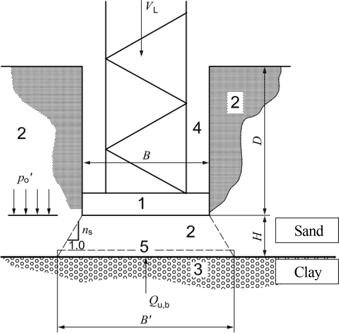
In the penetration to multi-layered soils, it is necessary to consider two significant effects: the punch-through and squeezing effects. First, punch-through occurs when a weak clay layer underlies a strong sand layer, and it is essential to analyze this phenomenon when the spudcan foundation needs to penetrate soil consisting of sand overlying clay (Hu, 2015; Hu et al., 2015; Hu et al., 2021; Falcon et al. 2019). When the punch-through phenomenon occurs, vertical bearing capacity is influenced by the sand plug formed underneath the spudcan bottom surface when the spudcan bottom with a closed cross-section shape, penetrates the sand layer. The size of a sand plug is affected by the equivalent diameter (B′) of the cross-section in contact with the surface of the clay soil, as expressed by Eq. (3). The weight of the sand plug generated by spudcan penetration is calculated by substituting B′ into Eq. (4). Finally, the total capacity (Qv ) is calculated by subtracting the weight (W) of the sand plug from the ultimate vertical foundation bearing capacity for the fictitious footing at the interface between the sand and clay layers with no backfill (Qu,b), as expressed by Eq. (5) and shown schematically in Fig. 1.
Second, the squeezing effect occurs when a strong soil layer underlies a weak clay layer. In a multi-layered soil consisting of a weak clay layer over a hard soil stratum, the bearing capacity of the spudcan becomes higher as the spudcan becomes closer to the lower strong soil stratum, compared to when the spudcan penetrates the single clay layer. To consider the squeezing phenomenon, the vertical bearing capacity of a spudcan is calculated using Eq. (6), as shown schematically in Fig. 2.

2.2 InSafeJIP Report (2011) Method
The InSafeJIP report (Osbone et al., 2011) presents the vertical bearing capacity of the spudcan with a diameter D according to soil conditions and the embedment depth of a spudcan, and it includes information from SNAME (2008). The vertical bearing capacity of a spudcan in a single clay layer is calculated according to the embedment depth of the spudcan by considering the volume of the spudcan full base, Vc, from the ground surface, as expressed by Eq. (7). Eq. (7) is the theoretical equation for vertical bearing capacity according to the embedment depth of the spudcan.

Spudcan penetration in clay (Osbone et al., 2011)
As the embedment depth of a spudcan increases, the penetration mechanism changes, so the vertical bearing capacity of a spudcan is calculated by considering the critical cavity depth, hc. Hence, the vertical bearing capacity of a spudcan is determined using Eq. (8) (Hossain et al., 2004; Hossain et al., 2005).
The vertical bearing capacity of a spudcan according to the embedment depth (partial penetration of a spudcan) is determined using Eqs. (9)–(11).


When calculating the vertical bearing capacity of a spudcan in a single-layer sand soil, the volume of a spudcan partially embedded base, Vc, is determined using Eq. (7) dependent on β at that depth, which is the same equation for a clay layer. For the backflow that occurs due to the difference in the outer diameters between the leg and the spudcan when a spudcan penetrates a sand layer, it is necessary to consider the volume of backfill soil, Vsoil, as shown in Fig. 4. On the other hand, the leg and the spudcan of the jack-up spudcan analyzed in this study have the same outer diameter, so the backflow is not considered. Therefore, the bearing capacity of the spudcan according to the embedment depth is expressed using Eqs. (12) and (13).

Spudcan penetration in sand (Osbone et al., 2011)
This paper describes the vertical bearing capacity of a spudcan in multi-layered soils under the conditions of sand-over-clay (Fig. 5) and soft clay-over-hard stratum clay (Fig. 6). First, in the case of sand-over-clay, the vertical bearing capacities are differently determined for each soil layer as Eqs. (14)–(16). Hence, Eqs. (14), (15), and (16) correspond to the vertical bearing capacities in the upper sand layer, at the sand-clay interface, and in the underlying clay layer, respectively.
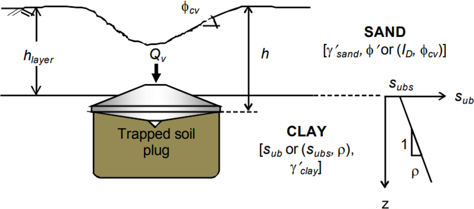
Nomenclature for spudcan penetration in sand-over-clay (Osbone et al., 2011)
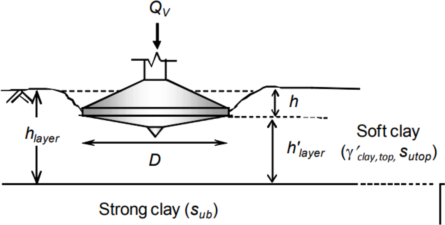
Nomenclature for spudcan penetration in soft clay over hard stratum clay (Osbone et al., 2011)
In Eq. (14) above,
Under the condition of soft clay-over-hard stratum soil, the vertical bearing capacity of a spudcan is determined using Eq. (17) especially for the penetration into the upper weak clay layer.
2.3 Centrifuge Model Test
A centrifuge model test replicates the same stress state of the prototype in-situ soil condition by applying an artificial centrifugal force by rotating a scale model of the soil and structure used in the site ground at high rotation speed. This test is used mainly to analyze soil-structure interactions for structures, such as offshore structures and underground structures, for which it is difficult to conduct full-scale experiments. The centrifuge model test is carried out at centrifugal acceleration levels of N times the gravitational acceleration to reproduce the same stress state as the site soil at each depth for the 1/N scale model fabricated for the centrifuge model test. Table 1 lists the scaling factors of the major physical quantities.

Centrifuge test scaling factor (Schofield, 1980)
3. Centrifuge Model Test for Foundation Installation
3.1 Centrifuge Test Condition
3.1.1 Model spudcan
The model leg-spudcan was made of aluminum, and the same model was used in all tests. The model leg-spudcan has an outer diameter of 80 mm and a length of 358 mm. A spigot-shaped spudcan is attached the end of the model leg, resulting in a plugged pile shape. The inside of the model leg-spudcan was filled with the same aluminum to minimize the deformation of the structure, and estimate only the vertical bearing capacity of the soil for the penetration of the jack-up into the soil. Table 2 and Fig. 7 present the specifications and physical properties of the model spudcan, respectively.

Model spudcan properties

Model leg-spudcan
3.1.2 Model soil
The centrifuge model tests were performed for two cases of soils: SC1 for loose sand-over-clay and SC2 for loose sand-clay-dense sand. Table 3 lists the geotechnical properties of sand and clay materials used in the experiment. Table 4 and Fig. 8 present the experimental conditions of the two cases. The sand used in the experiment was silica sand manufactured using the hammer crusher process as uniformly graded sand. Sand layers were prepared by the sand pluviation method, which allows an adjustment of the density of sand by controlling the falling height of sand grains, the hopper size, and the falling velocity of sand grains.
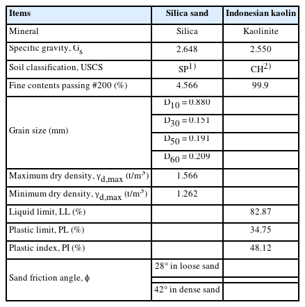
Geotechnical properties of silica sand and kaolin clay
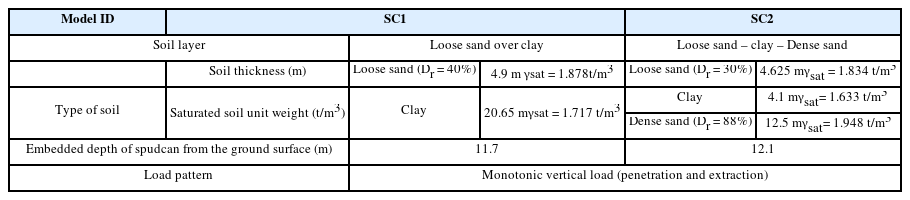
Centrifuge test condition (prototype scale)
Schematic diagrams of tests: SC1 and SC2
For clay soil, Indonesian kaolin powder was mixed with water at a water content (w) of 120%, which is twice the liquid limit (LL), using a mixer. The slurry mixture was placed in a soil container. The clay layers were then prepared by consolidating the mixture at pressures up to 800 kPa using a preconsolidation actuator system.
The soil container used to form the soil models was a circular pipe shape container made of steel with an inner diameter of 895 mm and an inner height of 705 mm. The container provides a soil bed with an inner diameter of 44.75 m and an inner height of 35.25 m in the prototype scale at 50 g.
3.2 Testing System
3.2.1 Geotechnical centrifuge
The centrifuge equipment (Fig. 9) of the Geotechnical Centrifuge Testing Center at owned by the Korea Advanced Institute of Science and Technology (KAIST) was used. Table 5 lists the centrifuge equipment specifications. The apparatus is a beam-type centrifuge with a rotation radius of 5.0 m and an effective radius of 4.5 m. Kim et al. (2013) and Yun and Han (2021) reported the detailed specifications of the apparatus. The centrifuge model tests were conducted at 50 g-level. For this experiment, a remote control system was constructed to enable the penetration of the model spudcan and measurements using sensors during centrifugal acceleration.

KAIST geotechnical centrifuge

Specification of KAIST goetechnical centrifuge
3.2.2 Vertical load control equipment
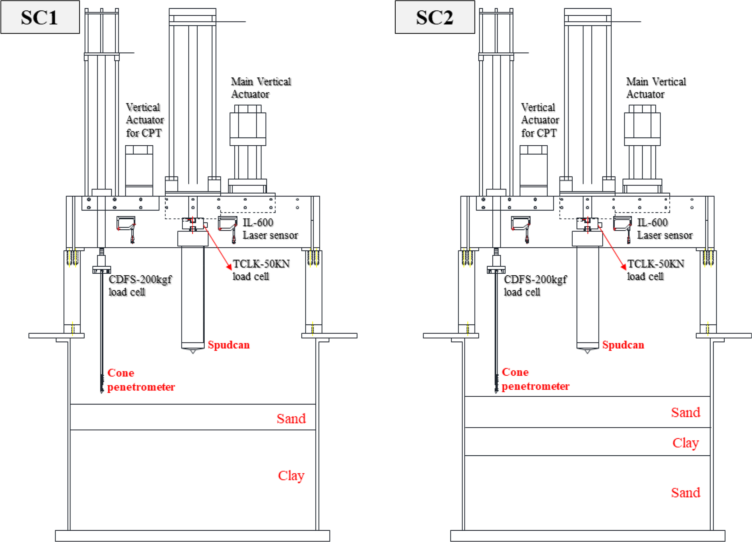
The penetration of a spudcan was simulated using a vertical actuator. A load cell was attached to the connection part of the vertical actuator and the spudcan to measure the vertical loads during penetration. The vertical actuator used was XML-FE09GMK (LSIS Co.), with a stroke length of 700 mm (prototype scale = 35 m). This vertical actuator was mounted on the soil container through a rigid connection using a steel frame. The vertical load for penetration at a velocity of 4.6 mm/s was conducted under a centrifugal acceleration of 50 g. For the load cells, the TCLK-50 kN and DSCK-10 t load cells were used by estimating the maximum load according to each soil condition.
3.2.3 Miniature cone penetration test (CPT)
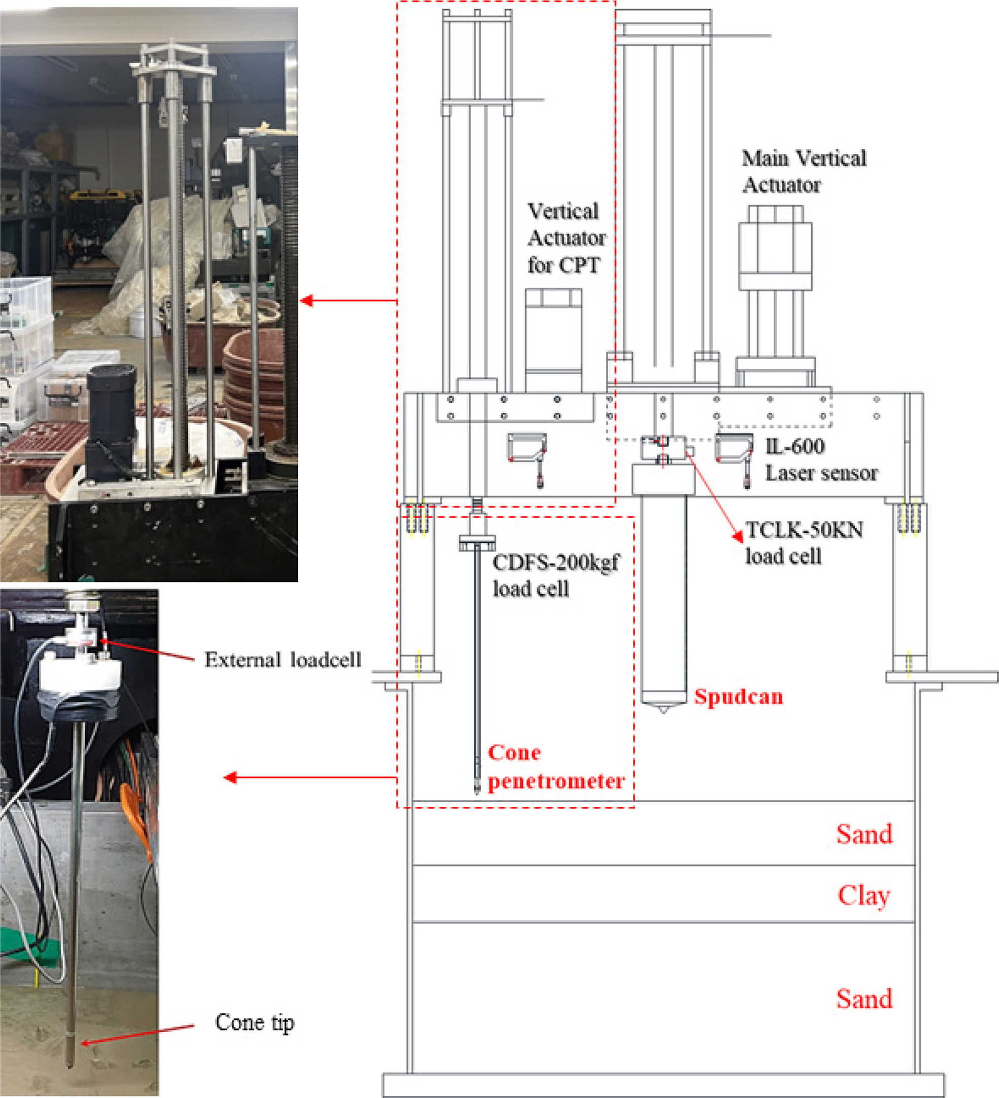
Cone penetration tests were performed to measure the undrained shear strength, su, of soils, as shown in Fig. 10. The miniature cone penetrometer was made from aluminum. A small load cell with a maximum load capacity of 200 kgf (20 kN) was installed at the connection between the vertical actuator and the CPT apparatus to measure the load during penetration. The load cell attached to the mini-CPT apparatus was a DSCS-200 kg tension/compression universal load cell, which has a capacity of 200 kg and a sensitivity of 3.0 mV/V (Sespene and Choo, 2018). The CPTs were performed with the penetration rate of 1 mm/s before the penetration of the spudcan after the arrival at the target g-level of 50 g. A Keyence IL-600 non-contact laser sensor was installed to measure the displacement during penetration. The cone penetration resistance, qc, according to the embedment depth, was calculated using the load and displacement values measured by the load cell and the laser sensor, as shown in Fig. 11. Even though a sand plug was not trapped during the penetration of the cone into loose sand in the case of sand over clay, the cone tip resistance decreased as the tip of the cone penetrometer approached the sand-clay interface but it increased again as the tip of the cone penetrometer penetrated the clay layer, resembling a punch-through effect.
Cone penetration system (model)
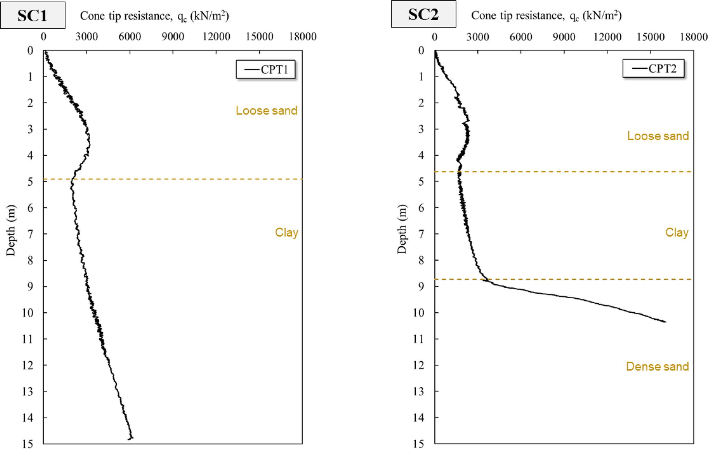
Cone tip resistance in SC1 and SC2 soils
4. Test Results
4.1 Cone Penetration
Using the cone tip resistance (qc) measured through the cone penetration test, the undrained shear strength, su, of the clay layer was calculated, as shown in Fig. 12 (Falcon et al., 2021a; Falcon et al., 2021b). This calculated undrained shear strength was used to calculate the penetration resistance of a spudcan by using the theoretical equations of ISO (2016) and the InSafeJIP report (Osbone et al., 2011). The undrained shear strength, su, calculated ranges 118–195 kPa in the clay layer situated at a depth of 4.9 to 8.7 m in SC1 (loose sand-clay) and 105–234 kPa in the clay layer of SC2 (loose sand-clay-dense sand). The undrained shear strength of SC2 was greater than that of SC1 at 8.7 m (clay-sand interface) because of the influence of dense sand of the deeper layer of SC2, but the undrained shear strengths of SC2 and SC1 were in a similar range.

Undrained shear strength in clay layer of SC1 and SC2 soils
4.2 Spudcan Penetration
The spudcan was monotonically and vertically penetrated at the target centrifugal acceleration to measure the gross ultimate vertical bearing capacity of the spudcan according to the embedment depth, as shown in Fig. 13. The absolute values of vertical penetration resistances between the spudcan and cone are different but their trend were very similar in the overall penetration pattern.

Vertical penetrating load of SC1 and SC2
In the case of SC1 (loose sand over clay), the vertical bearing resistance shows a punch-through effect at the spudcan’s penetration into the upper loose sand layer. In other words, as the spudcan penetrated the upper loose sand layer, the vertical bearing resistance initially increased gradually, and it decreased slightly at the embedment depth of approximately 4 m from the ground surface. After this, the vertical bearing resistance starts to increase again as the spudcan approached the lower clay layer. This reduction in vertical bearing resistance at the sand layer is caused by a sand plug. In particular, the sand plug trapped underneath the spudcan bottom penetrates the lower clay layer before the penetration of the spudcan bottom into the lower clay layer. This phenomenon often occurs at actual installations of a jack-up spudcan foundation when a strong sand layer overlies a clay layer. Nevertheless, this phenomenon is observed at the centrifuge model test in this study despite the loose sand condition. But, a drastic drop in vertical load did not occur. The 4-m-diameter spudcan foundation in this study penetrated the soil to a maximum depth of 11.7 m, resulting in the maximum vertical bearing resistance of 2,212 t.
In the case of SC2 (loose sand-clay-dense sand), the spudcan penetration started from the depth of 3.5 m from the ground surface due to an accidentally initial embedment into the loose sand layer. A clay layer was formed between the uppermost loose sand layer and the lowest dense sand layer and the clay was prepared at the same condition with that of the clay layer of SC1. On the other hand, when the spudcan penetrated the clay layer, as it approached the lower dense sand layer, vertical bearing resistance showed a drastic increase and became more than 2.2 times higher than the vertical bearing resistance in the clay layer of SC1 (at the same depth as in SC1: at a depth of approximately 8.22 m). This is called as the squeezing effect caused by the dense sand layer, the lowest stratum. A sand plug was trapped during the initial penetration of the spudcan through the uppermost loose sand layer, and then it reached the dense sand layer in advance before the spudcan actually penetrated the lowest dense sand layer, contributing to a greater increase in vertical bearing resistance at embedment depths greater than 7 m. The maximum value of vertical bearing capacity was 8,225.83 t when a spudcan foundation with a diameter of 4 m penetrated the soil to a maximum depth of 12.02 m.
5. Discussion
The vertical bearing resistance of the spudcan was calculated using the theoretical formulae presented by the ISO guidelines (2016) and the InSafeJIP report (Osbone et al., 2011) by applying the soil properties measured in the centrifuge model test. The calculation results obtained using the theoretical analysis methods were compared with those of the centrifuge model tests in Fig. 14.

Comparison calculated ISO method (2016), InSafeJIP method (2011) with centrifuge results
In the case of SC1(loose sand-clay), the ISO method results does not show a punch-through effect during the penetration of the upper loose sand layer; it shows an increase in vertical bearing resistance as the embedment depth was increased. In addition, up to an embedment depth of 7.5 m past the sand-clay interface, the gross ultimate vertical bearing resistance estimated using the ISO method was smaller than the test results. At depths greater than 7.5 m, however, the estimates calculated using the ISO method were higher than the measured test data. For the vertical bearing resistance in the upper loose sand layer, the ISO method presents a high value of Qu,b (ultimate vertical foundation bearing resistance for the fictitious footing at the interface between the sand and clay layers with no backfill) because of the high undrained shear strength (>100 kPa) of the clay layer surface. On the other hand, the punch-through phenomenon did not occur because the high undrained shear strength did not significantly affect the load reduction effect due to the sand plug formed underneath the spudcan.
In the condition of SC2 (loose sand-clay-dense sand), the estimation results from the ISO method (ISO, 2016) and test data were similar in the overall pattern of the vertical bearing resistance according to embedment depths, but there were differences in the levels of vertical bearing capacity for each layer. For the vertical bearing resistance in the clay layer between two sand layers, as the spudcan approached the lower dense sand layer, the test results revealed higher vertical bearing resistance than the estimates from the ISO formula. In the case of the dense sand layer, the lowest layer, the estimated vertical bearing resistance obtained using the ISO method was four times higher. These differences in analysis results are related to the sand plug and the method of calculating the vertical bearing resistance for multi-layered soils. In particular, the squeezing effect was considered when calculating vertical bearing resistance using the ISO theoretical formula, but the sand plug phenomenon formed by penetrating upper loose sand was not. In the centrifuge model test, however, as the embedment depth increased, there was a greater increase in vertical bearing resistance because the sand plug formed from the ground surface existed until the spudcan penetrated the dense sand layer underneath the sand plug. In addition, the ISO method does not have an option for multi-layered soils consisting of three or more layers, so the dense sand layer corresponding to the lowest layer was assumed to be a single-layer sand soil to calculate vertical bearing resistance in the dense sand layer. Therefore, the ISO method produced a very high estimate for the vertical bearing capacity in the dense sand layer.
The InSafeJIP method (Osbone et al., 2011) produced a very similar penetration resistance profile to that shown by the ISO method (ISO, 2016), but in the loose sand layer, the vertical bearing capacities estimated using the InSafeJIP method were more than two times higher than those calculated using the ISO method. Nevertheless, the results of the two methods were relatively well matched in the case of the clay layer. These differences in analysis results can be explained as follows. In the soil condition of sand-over-clay, the ISO method did not consider the weight of the sand plug. In contrast, the InSafeJIP method added all the vertical bearing resistances of the upper sand layer, sand-clay interface, and the lower clay layer. Hence, the InSafeJIP method predicted higher vertical bearing resistances than the ISO method. When calculating the vertical bearing capacity using the InSafeJIP method, a very high vertical bearing resistance was estimated in the sand layer overlying the clay layer from the initial penetration stage, as described above. Thus, assuming the soil condition as a single sand layer is more appropriate when calculating vertical bearing resistance using the InSafeJIP method at shallow embedment depths during the initial penetration stage.
In addition, in the case of SC2 (loose sand-clay-dense sand), the vertical bearing resistance in the lower dense sand layer was calculated by assuming the soil condition as a single sand layer, as in the ISO method, but the estimates calculated using the InSafeJIP method were lower than 10 times those obtained using the ISO method because of the difference in the bearing capacity factor. In addition, the InSafeJIP method produced results that more closely matched the test data than the ISO method
Overall, as the spudcan penetrated deeper into the soil, the vertical bearing resistance of the centrifuge model test showed a penetration resistance profile that can be represented as a curve on a graph, whereas the ISO and InSafeJIP methods produced unnatural estimation results at the initial penetration stages and at the interface of heterogeneous layers. These differences in the vertical bearing resistance analysis results using the three methods may be attributed to the following reasons. In the centrifuge model test, the vertical load was measured as the spudcan penetrated at a constant speed. On the other hand, when calculating the vertical bearing resistance using the ISO method, a high vertical bearing capacity is predicted from an initial penetration stage because of the high undrained shear strength of more than 100 kPa in the lower clay layer under the sand over clay condition. In the case of the ISO method, the vertical bearing resistance of the lower clay layer acted more dominantly than the influence of the sand plug formed from the loose sand of the upper layer, even when the spudcan penetrated the lower clay layer. In addition, the InSafeJIP method predicted significantly higher initial vertical bearing resistance than the ISO method and the centrifuge model test. Therefore, under the sand over clay condition, it is appropriate to apply the theoretical formula for calculating the vertical bearing resistance in a single-layer sand soil when estimating the vertical bearing resistance at a partially penetrated depth before the shoulder of the spudcan was fully embedded in the soil and at depths not affected by the sand plug.
6. Conclusions
A centrifuge model test was performed to analyze the penetration behavior of a jack-up leg with spudcan developed for offshore wind turbine according to the vertical load under the two soil conditions: saturated loose sand-clay and loose sand-clay-dense sand. The measured vertical bearing resistance of a spudcan obtained using the centrifuge model test were compared with the estimates using the theoretical formulas from the ISO guidelines (2016) and the InSafeJIP report (Osbone et al., 2011). The following conclusions were drawn.
In centrifuge model tests on the vertical penetration of a jack-up spudcan, while the spudcan was penetrating the upper loose sand layer, the vertical bearing resistance tended to decrease before penetrating the lower clay layer as the spudcan approached the sand-clay interface. This decrease in vertical bearing resistance is likely caused by the penetration of the sand plug trapped beneath the spudcan into the lower clay layer earlier than the actual spudcan. On the other hand, vertical bearing resistance increased again as the spudcan penetrated the clay layer. in the case of such soil conditions for installing of the offshore wind jack-up substructure, the punch-through effect is not expected to occur predominantly, but fast running is expected to occur at depths where vertical bearing resistance decreases. Fast running refers to the phenomenon in which the spudcan penetrates the soil rapidly and uncontrollably without penetration resistance increase and sinks deep into the soil at depths where vertical bearing resistance decreases during the installation of the jack-up spudcan. In addition, a squeezing effect is possibly expected when there is a stronger soil layer (dense sand) beneath a clay layer; that is a hard soil stratum underlying a weak soil layer causes an increase in the vertical bearing resistance as the spudcan approaches the interface between weaker and stronger soil strata.
The analysis results obtained using the ISO method (2016) showed a similar trend to the centrifuge model test regarding the vertical bearing resistance. In particular, the vertical bearing resistance in the upper loose sand layer was similar to the test data, but the punch-through phenomenon showing a decrease in vertical bearing resistance was not observed. In addition, in the soil condition of sand over clay, the estimates obtained using the ISO formula did not show a decrease in load arising from the impact of a high undrained shear strength of more than 100 kPa. In the soil condition of clay-over-dense sand, which is the condition of weak soil over a stronger stratum soil, the increase in vertical bearing resistance due to the squeezing effect was not prominent compared to the test results. In addition, the ISO method does not provide a method for calculating the vertical bearing resistance of a spudcan in multi-layered soils with three or more layers. Thus, when the ISO method is used to calculate the vertical bearing resistance in such soil conditions, a multi-layered soil with three or more strata is assumed to be a single sand–soil layer, so this method tends to predict very large vertical bearing resistances in such cases.
The InSafeJIP method (Osbone et al., 2011) showed a vertical bearing resistance pattern similar to that of the ISO (2016) method, but the estimated vertical bearing resistance obtained using the InSafeJIP method was more than two times larger than the value obtained using the ISO method in the upper sand layer in the soil condition of under loose sand over clay. In particular, because the InSafeJIP method predicted an excessively high vertical bearing resistance from the initial stage of penetration, it is considered more appropriate also to analyze the vertical bearing capacity under the condition of a single-layer sand soil when estimating vertical bearing resistance at the initial stage of penetration and predict vertical bearing resistance at a shallow depth by using the lower limit value. In addition, an analysis using the InSafeJIP method resulted in a more prominent punch-through effect than the centrifuge model test and ISO method. In the InSafeJIP method, the dense sand layer, which is the lowest layer among the loose sand-clay-dense layers, was assumed to be a single-layer sand soil, which is similar with the ISO method. On the other hand, the estimate by the InSafeJIP method was considerably lower than the value obtained by the ISO method because of the difference in the bearing capacity factors utilized in both methods, and it was even somewhat lower than the test result.
The measured vertical bearing resistances of a spudcan of the centrifuge model test differed in absolute value from the estimates calculated by theoretical formulas. Regarding the overall pattern of estimates, however, the ISO (ISO, 2016) and InSafeJIP methods (Osbone et al., 2011) predicted a penetration behavior that essentially matched the test data. On the other hand, in the case of a strong sand layer, compared to the test results, the InSafeJIP method predicted a smaller vertical bearing resistance, and the ISO predicted a very high vertical bearing resistance. When calculating the vertical bearing resistance of a spudcan using such theoretical equations, the geotechnical properties of friction angle and undrained shear strength of soils significantly impact the calculation of the bearing capacity factors for both clay and sand layers. Therefore, the cone penetration tests (CPT) and laboratory testing using site specimen should also be carried out to estimate the shear strength parameters of soils and comprehensively evaluate the vertical bearing resistance of a spudcan at the stage of a site investigation when designing offshore wind turbines.
Notes
No potential conflict of interest relevant to this article was reported.
This work was supported by the Korea Institute of Energy Technology Evaluation and Planning (KETEP) grant funded by the Korean Government (MOTIE) (20223030020240, Development of 10MW or higher offshore wind power upper and lower package installation support structure system for LCOE reduction)