Material Property-Estimate Technique Based on Natural Frequency for Updating Finite Element Model of Orthotropic Beams
Article information

Abstract
Composite materialsuch as glass-fiber reinforced plastic and carbon-fiber reinforced plastic (CFRP) shows anisotropic property and have been widely used for structural members and outfitings of ships. The structural safety of composite structures has been generally evaluated via finite element analysis. This paper presents a technique for updating the finite element model of anisotropic beams or plates via natural frequencies. The finite element model updates involved a compensation process of anisotropic material properties, such as the elastic and shear moduli of orthotropic structural members. The technique adopted was based on a discrete genetic algorithm, which is an optimization technique. The cost function was adopted to assess the optimization problem, which consisted of the calculated and referenced low-order natural frequencies for the target structure. The optimization process was implemented with MATLAB, which includes the finite element updates and the corresponding natural frequency calculations with MSC/NASTRAN. Material properties of a virtual cantilevered orthotropic beam were estimated to verify the presented method and the results obtained were compared with the reference values. Furthermore, the technique was applied to a cantilevered CFRP beam to successfully estimate the unknown material properties.
1. Introduction
Composite materials such as GFRP (glass-fiber reinforced plastic) and CFRP (carbon-fiber reinforced plastic) provide superior material properties compared to structural steels in terms of specific strength, fatigue resistance, and anti-corrosion. Consequently, composite materials are widely used for structural materials in various fields, such as the aviation, automotive, shipbuilding, and marine industries (Weitzenböck et al., 2010). Particularly, CFRP is steadily garnering attention both as the hull construction material of small ships and high-speed crafts that require weight reduction, and also as a high-load auxiliary material for engine parts, such as propellers (Chen et al., 2003; Oh et al., 2013; Lee et al., 2014).
In this study, the structural safety of CFRP structures was generally evaluated via finite element analysis. Regarding this process, the mechanical properties of the material approximate to the actual values, as well as the shape of the target structure, should be introduced to the finite element analysis. Although methods for manufacturing CFRP materials in the design shape (during ship building) have been implemented with recent advancements in technology, the mechanical properties of these materials remain unclear owing to the significantly different mechanical properties of CFRP structures depending on the stacking sequence and direction, manufacturing environment (temperature and humidity), and expertise of workers, as well as the differences in the physical properties of the base materials, such as carbon fiber and resin.
Meanwhile, the importance of digital twin technology is growing in the field of ship structural mechanics. The core technology here involves the use of a virtual ship with similar structural properties to an actual ship (JASTRA Channel, 2020). A structural digital twin platform with both static and dynamic structural responses should be implemented according to the external force generated during the virtual ship’s operation similar to that of an actual ship. The structural digital twin implementation requires the development of a finite element model that reflects the static and digital characteristics of an actual ship.
The properties of the composite material, such as Poisson’s ratio, elastic, and shear moduli are generally calculated via static tests, such as tensile, compression, and bending tests, on beams or sheet specimens made of the corresponding material. However, equivalent finite element model update techniques have been proposed in recent years to implement the dynamic properties of a target structure by adopting modal characteristics, such as natural frequency, mode shape, and mode damping. Zahari et al. (2016) proposed a method and procedure for identifying the parameters that influence the dynamic properties of a joint structure via sensitivity analysis, as well as calculating the equivalent material properties, such that a natural frequency identical to that of the actual structure is obtained. Hofmeister et al. (2019) proposed an optimization-based equivalent finite element model update to address wind turbine blade damages. Giagopoulos et al. (2009) introduced the finite element model update of an experimental vehicle using measured modal characteristic data.
This study presents a finite element model update technique, which calculates the equivalent material properties of a target structure using the natural frequencies of CFRP ships or structures. The technique involves the processes of optimization parameter selection, finite element model development and update. Additionally, in this study, the validity of the proposed technique is evaluated by conducting numerical analysis on a cantilevered orthotropic beam. Furthermore, the feasibility of the proposed technique is verified by estimating the equivalent material properties of the target structure using the natural frequency information obtained from a random CFRP cantilever beam.
2. Finite Element Model Update
The finite element model update for composite structures is a process that involves performing the inverse method on the equivalent material properties of finite element model by applying the optimization technique to obtain the same natural frequencies as the target structure. Fig. 1 illustrates the finite element model update procedures with processes of optimization parameter selection, finite element model development and update. The finite element model update process for composite structures was implemented in MATLAB while MSC/NASTRAN was adopted to carry out the low- order natural frequency analysis required in the optimization process.
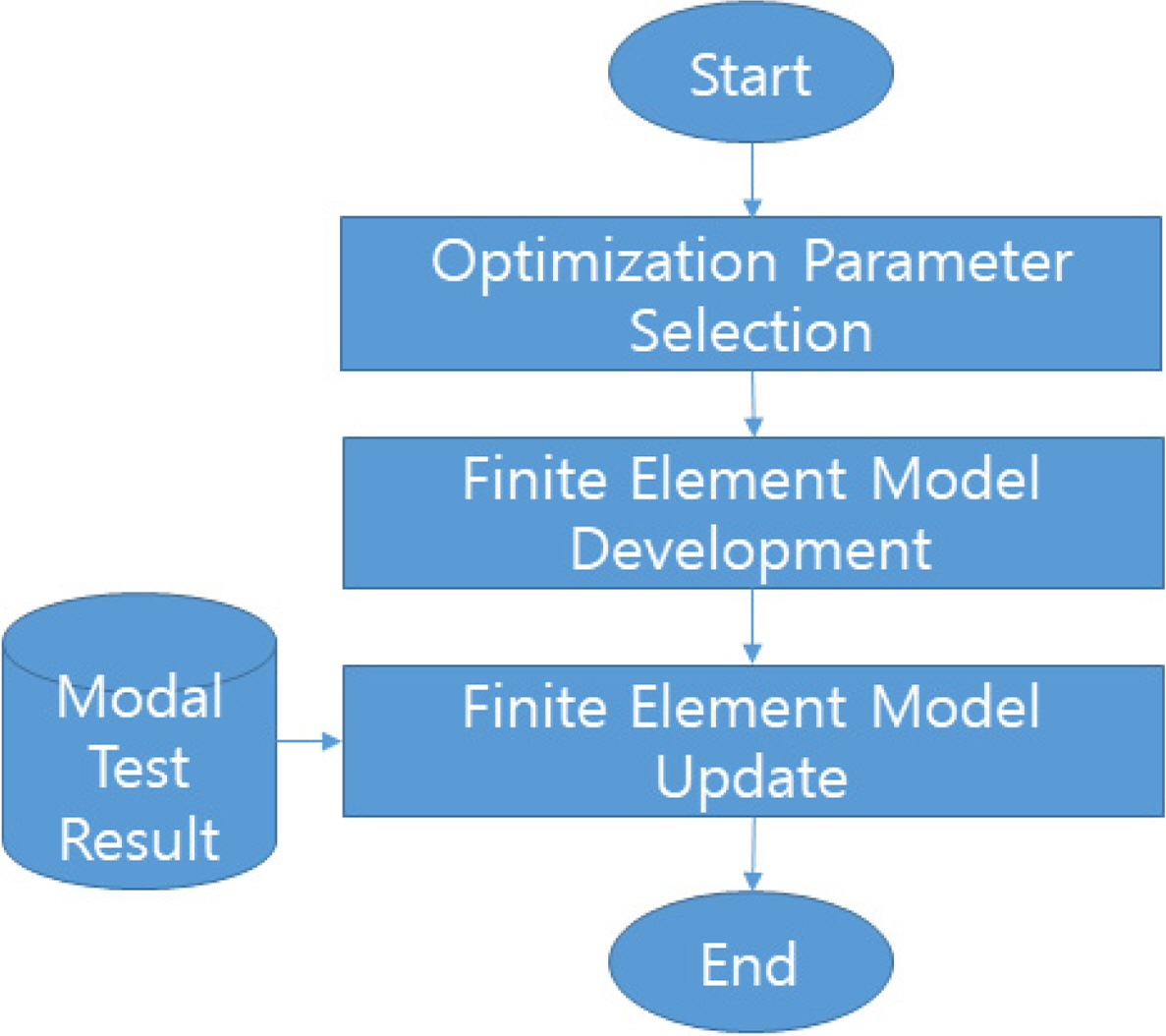
Finite element model update process applying an optimization algorithm
2.1 Optimization Parameter Selection
To accurately identify the mechanical properties of composite structures, material properties need to be derived via standardized material tests, such as tensile, compression, and bending tests. Mechanical properties can vary significantly depending on the stacking environment and expertise of workers, even if the same base material is used and stacked with the exact same specifications. As an alternative to address this challenge, an inverse method can be applied to calculate the material’s properties using the dynamic properties of target structure, such as modal test results. This study updates the finite element model based on an optimization process that involves minimizing the difference between the natural frequencies obtained via the finite element model and modal test results, respectively. In the optimization process, density, thickness, number of layers, elastic and shear moduli, as well as Poisson’s ratio can be employed as the targets of optimization parameters. In this study, the elastic moduli, E11 and E22, and shear moduli, G12, G13, and G23, which are considered to significantly influence the mechanical properties of orthotropic plate materials, were selected as optimization parameters.
2.2 Finite Element Model Development
The finite element model is saved in the bulk data file format (*.bdf), which is an MSC/NASTRAN input file. Fig. 2 illustrates an example of a bdf-file of the finite element model for an orthotropic beam used in this study. The modal analysis adopts the SEMODES (SOL 103) module of MSC/NASTRAN. The finite element is formulated using CQUAD4, a quadrilateral shell element. The material properties of the composite structure were defined using PCOMP. Although the orthotropic material properties were defined by MAT8, they were saved as separate MAT.INC files for defining the elastic and shear moduli to enable the easy control of optimization parameters. The file was designed to be retrieved by the “include” command from the bulk data file of MSC/NASTRAN during the optimization process.

Example of finite element model of an orthotropic beam: an MSC/NASTRAN input file (bdf-file) and external file for defining the material properties
2.3 Finite Element Model Update
The finite element model update for the composite structure is conducted such that the natural frequency of the target structure is induced to approach the actual value. The optimization process for the finite element model update adopted the discrete genetic algorithm, which is a typical global optimization algorithm.
The discrete genetic algorithm is accompanied by the following procedure:
The optimization parameters are discretized and coded as bits to construct the first generation.
The modal analysis is conducted for each object that belongs to the first generation and the fitness assessment is conducted via derived natural frequencies.
The construction of the next generation is conducted until the required fitness is fulfilled or the maximum number of iterations is reached, via elitist model, selection phase, crossover phase, and mutation phase processes, as well as the fitness assessment process on the constructed next generation.
More details on the finite element model update using the discrete algorithm are presented in Chapter 3.
3. Discrete Genetic Algorithm
Fig. 3 illustrates a flow chart of the discrete genetic algorithm adopted in this study for the finite element model update process. As shown in the figure, the process proceeds in the following order: first generation construction, fitness assessment for first generation and convergence check, application of elitist model, selection phase, crossover phase, mutation phase, and fitness assessment for next generation and convergence check. Fitness assessment is conducted based on the cost function that reflects the modal test results of the target structure, as well as the modal analysis results of each object. In the convergence check step, if the required cost or maximum number of iterations is not fulfilled, the elitist model step and later steps are repeated until convergence is achieved.

Process of finite element model update via discrete genetic algorithm
3.1 Optimization Parameter Discretization and Coding
The optimization parameters are discretized and coded in the discrete genetic algorithm. The elastic and shear moduli, which are optimization parameters, are discretized in equal intervals for the desired range and stored as databases with unique numbers.
In the discrete genetic algorithm, the unique number of the database is coded as a chromosome in the form of an array composed of bits.
Given the number of databases discretized for each optimization parameter as Nij, the selected database is expressed as an array Lij composed of Nij,b(=log2 Nij) number of bits (Nij,b-bit), as expressed in Eq. (1).
The chromosome array G, consisting of all database information of the optimization parameters, can be expressed in Eq. (2), which links the chromosome array to each of the optimization parameters. The total number of bits, N, of the chromosome array is expressed in Eq. (3).
3.2 Fitness Assessment
Fitness is a quantitative index that indicates the proximity of the calculated natural frequency to the actual natural frequency when the material properties corresponding to individuals of each generation are reflected in the finite element model. A cost function was employed in this study to assess fitness, with lower costs representing higher fitness. The cost function J is expressed by Eq. (4) and was defined by considering the weight of the relative squared error for each natural frequency of the modal test and finite element analysis results (Zahari et al. 2016).
3.3 Discrete Genetic Algorithm Development
3.3.1 First generation construction
As illustrated in Fig. 4, the Npop populations that formulate the initial generation are generated as chromosome groups (G1, G2, ⋯ GNpop) with bit arrays. Each chromosome is randomly allocated with a bit value of “0” or “1.”

Chromosome group for first generation
3.3.2 Elitist model
In the elitist model, the elitist chromosome group, which exhibits the best fitness in the present population is considered an individual of the next generation (Fig. 5). This approach is used to achieve quicker convergence by maintaining the properties of the individual that exhibits outstanding fitness in the previous generation.

Elitist model
In this study, two individuals, exhibiting the best fitness in the present generation, are adopted as the first and second individuals in the next generation.
3.3.3 Selection phase
In the selection phase, chromosomes are selected from the present generation to generate chromosomes for the next generation population. Two of the most widely used selection methods are the roulette and tournament selections. The roulette selection increases selection probability based on the fitness proportion of each chromosome of the present population, whereas the tournament selection selects an individual with optimal fitness from a population of two randomly selected chromosomes in the present generation. This study adopted the tournament selection method, which is more straightforward than the roulette selection method.
3.3.4 Crossover phase
After selecting two chromosomes from the present population, chromosomal crossover was conducted to generate new genes for the next generation by exchanging the genetic materials of the selected specific chromosomes. The crossover process is carried out by exchanging preceding genes with following genes based on the random array reference point of chromosomes. Depending on the number of reference points, the crossover can be classified into one-point and multi-point crossovers. However, to avoid bias toward a certain solution and increase convergence, a probability of crossover was set, and a real value between “0” and “1” was randomly extracted before the crossover. Subsequently, if the extracted value is less than the specified probability of crossover, crossover is carried out, otherwise the selected chromosomes are transferred to the next generation population. In this study, one-point cross over was adopted, as shown in Fig. 6.
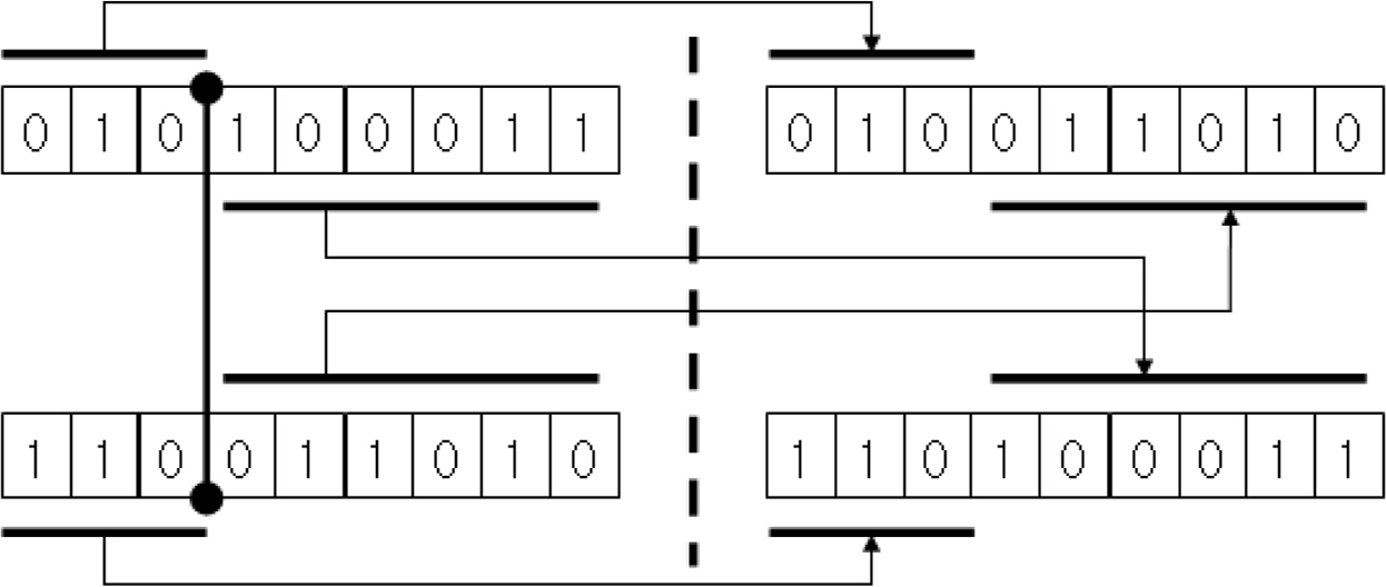
One-point crossover
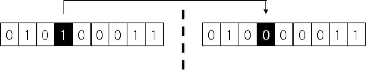
3.3.5 Mutation phase
The chromosomes that passed through selection and crossover phases were designed to induce mutation by intentionally altering the information of one or more genes. Mutations typically demonstrate the tendency of reducing the average fitness of the entire population, thus providing the effect that enables access to more diverse optimal solutions by implanting new information inside the chromosomes during the algorithm’s execution. However, if the probability of mutation for the chromosomes is set too high, there is a limitation of moving away from the optimal solution as the process is repeatedly iterated. Therefore, an appropriate mutation probability should be configured.
In this study, mutation was permitted for one gene of the chromosome alone, as shown in Fig. 7.
Mutation
3.3.6 Convergence check
In the convergence check, the fitness of the new population with genes modified via crossover and mutation phases, was calculated. The algorithm was terminated if the calculated fitness was less than that of the previous generation or a maximum number of algorithm iterations was achieved. Otherwise, the process returned to the elitist model step and the entire process was repeated again.
4. Numerical Examples
4.1 Verification of the Finite Element Model Update Method
The feasibility of the inverse method on the material properties of the composite structure was evaluated by performing inverse operation on the material properties of an orthotropic beam. In general, cantilevered beam type specimens are widely used to determine the dynamic properties of structures. Therefore, a cantilevered orthotropic beam was selected as the target structure for verification. Natural frequencies corresponding to the exact solution were calculated after conducting modal analysis on the target structure. Table 1 summarizes the material properties of the target cantilevered orthotropic beam.The material direction was assumed to be longitudinal. The finite element model for the target structure was designed with 240 rectangular shell elements and 305 nodes (Fig. 8). The length, width, and thickness of the finite element model were 600, 40, and 10 mm, respectively while the clamp fixture boundary condition was applied to the 0–40 mm area in the longitudinal direction. The natural frequencies of the target structure were extracted for a total of six generations, from first to sixth, and the values obtained are summarized in Table 2 together with the mode shape information.
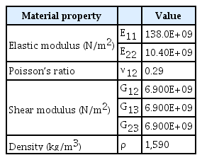
Material properties of cantilevered orthotropic beam

Finite element model of the cantilevered orthotropic beam

Modal frequencies of cantilevered orthotropic beam
The inverse operation was performed to calculate the material properties of the target structure in reverse solely via the natural frequency information presented in Table 2. In this process, elastic moduli, E11 and E22, and shear modulus, G12, were selected as optimization parameters. Table 3 summarizes the ranges of material properties, as well as those of the discrete genetic algorithm parameters. The ranges were configured to include the material properties from Table 1. As a reference, 16 (4-bit) optimization parameter databases were configured for each parameter, and the moduli, G23 and G13 were fixed at 6.900E+09 N/m2. However, the number of individuals for each generation was set as 50, and the probabilities of crossover and mutation were set as 0.9 and 0.1, respectively. The convergence criteria were established by setting 1E-10 and 100 as the required cost and maximum number of iterations, respectively.

Material property ranges and indiscrete genetic algorithm parameters of cantilevered orthotropic beam
Fig. 9 presents a convergence plot graph illustrating the minimum cost function value for each generation. The sixth generation’s minimum cost function J converged to zero, and the material properties derived via the inverse method matched the material properties of Table 1 without displaying any error. This indicates that the material property inversion method implemented in this study was successfully executed.

Convergence plot: generation vs. cost function value
4.2 Application to Cantilevered CFRP Beam
To evaluate the practical applicability of the proposed finite element model update method, the inverse operation was performed to calculate the material properties of a random composite beam. The target structure was a unidirectional CFRP specimen together with the cantilevered CFRP beams used in the study conducted by Hwang et al. (2018). The specimen’s specifications and fixing methods are similar to those used in numerical analysis model presented in Section 4.1.
As shown in Fig. 10, the natural frequencies of the target structure corresponding to the exact solution were calculated via a modal test using an impact hammer. The natural frequencies obtained from the first to fourth generations were 50.87 Hz (1st vertical bending), 255.30 Hz (1st twisting), 273.72 Hz (1st lateral bending), and 326.65 Hz (2nd vertical bending), respectively (Hwang et al., 2018).

Modal test of the cantilevered CFRP beam (Hwang et al., 2018)
Elastic moduli, E11, and E22, and shear moduli, G12, G13, and G23, were selected as optimization parameters. Table 4 summarizes the ranges of the material properties, as well as those of the discrete genetic algorithm parameters. As a reference, the number of discrete data for the elastic moduli, E11 and E22, was set to 64 (6-bit) and 32 (5-bit), respectively, and the number of discrete data for the shear moduli was set to 8 (3-bit). However, the number of individuals for each generation was set to 40, and the probabilities of crossover and mutation were set to 0.9 and 0.1, respectively, same as that of the previous section. The convergence criteria were established by setting 1E-6 as the required cost and 50 as the maximum number of iterations.

Material property ranges and indiscrete genetic algorithm parameters of cantilevered CFRP beam
Fig. 11 presents a convergence plot graph showing the function values of the minimum cost for each generation in the optimization process. As illustrated, the required cost was not fulfilled until the vertical bending (3rd) maximum number of iterations. The final cost function value obtained is 6.904E-4 and Table 5 summarizes the final material properties of the orthotropic beam, which are the target optimization parameters.

Convergence plot (cantilevered CFRP beam): generation vs. cost function value

Estimated material properties of the cantilevered CFRP beam
Table 6 summarizes the comparison of natural frequencies measured via the modal test on the target orthotropic beam model, as well as the natural frequencies obtained from the updated finite element model. Additionally, the table presents the fifth and sixth natural frequencies obtained using the finite element model, as well as the first to sixth mode shapes. As presented in Table 7, the results obtained from the experiment and numerical estimation agreed optimally. Accordingly, via the updated finite element model, auxiliary information, such as high-order natural frequencies and mode shapes, can be estimated, as well as the material properties of the target structure.

Modal frequencies and shapes of the cantilevered CFRP beam
5. Conclusions
This study proposed a finite element model update method, comprising processes of optimization parameter selection, finite element model development, and finite element model update, which was adopted to calculate the equivalent material properties of a target structure via the natural frequencies of a CFRP ship or structure. Additionally, an optimization technique was applied, in which the material properties of the target structure were iteratively updated such that the finite element model yielded natural frequencies of the pre-analysis or actual-measured values. A discrete genetic algorithm was utilized as the optimization technique. After which, a numerical analysis was conducted on a hypothetical cantilevered orthotropic beam structure to evaluate the validity of the proposed update om the finite element model. Consequently, it was inferred that the estimated material properties were consistent with the measured material properties of the target structure. Furthermore, a finite element model that yields values similar to that of the actual-measured natural frequencies was derived by performing numerical analysis on the cantilevered CFRP beam with unknown material properties. Finally, the feasibility of the proposed update on the finite element model was verified by estimating the high-order natural frequencies and mode shapes using the derived finite element model.
 vertical bending (1st)
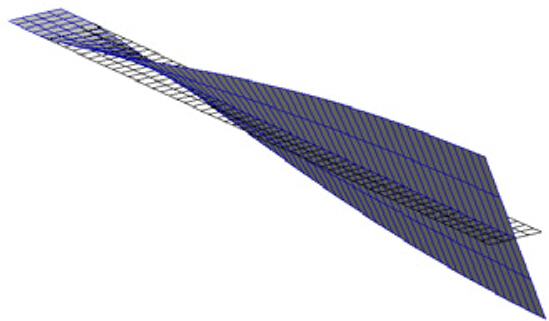 twisting (1st)
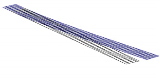 lateral bending (1st)
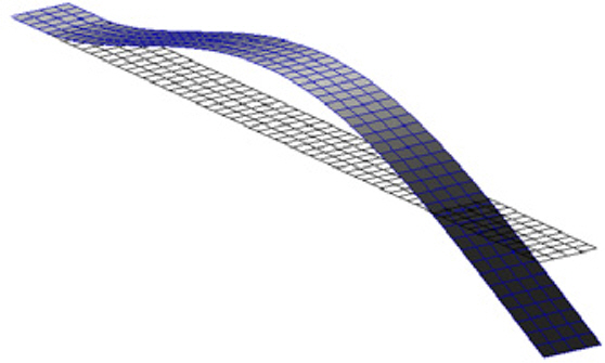 vertical bending (2nd)
 twisting (2nd)
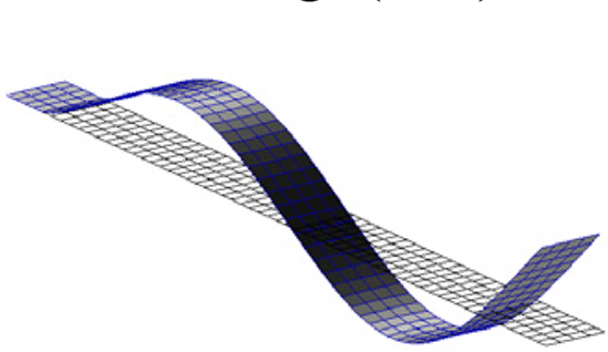 vertical bending (3rd)