Comparative Study between Results of Theoretical Calculation and Model Test for Performance Confirmation of “Crown Duct”
Article information
Abstract
Chosun University, in cooperation with SPP shipyard, has developed an energy saving device based on a new concept: “Crown Duct.” Crown Duct is composed of a semi-duct with short struts inside and outside the duct. Theoretical calculations for two different designs were carried out using the CFD code “Ship Flow.” The design selected from these two different forms by the CFD code analysis was tested in a towing tank at SSPA. The results showed about 4% efficiency gain under a full-load condition and about 7% gain under a ballast condition in the towing tank test.
1. Introduction
Vortices generated from the bilge at stern moves upward on both ship sides and moves downward near the center plane of the ship, leading to difference angle of attack of propeller blades on port and starboard side which may reduce the propeller efficiency.
Against the stern flow mechanism, the stator fins generally plays a role as flow guiding device making a wake field near the upper part of the propeller plane uniform by both deflecting flow toward propeller and reducing the wake peak at propeller top position(Lee et al., 1992 and Lee et al., 1994).
Conventional pre-swirl stator consists of several fins which have almost the same span length as the propeller radius and are fixed radially on the stern frame in front of the propeller as shown in Fig. 1. It is known that the wake factor (1-w) decreased considerably due to reflecting flow generated by stator fins in front of the propeller plane. But high stress fins concentrated at the standing point of side fin in heaving and pitching motion, and non-negligible added resistance due to this is the problem to be solved(Asaumi et al., Lee et al., 2012a).
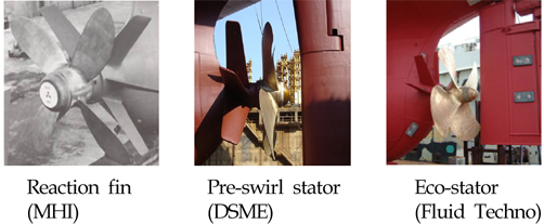
Pre-swirl stator
2. Development of a New Type Energy-Saving Device “Crown Duct”
New type of complex stator having less added resistance and less stress on the stand point of side fins than conventional pre-swirl stator, has been developed by combination of semi-duct and minimum blades As shown in Fig. 2, small sized semi-duct having diameter almost equal to 50% of propeller diameter is attached to the tip of the short horizontal fin which is designed to decrease the tip vortex and to generate the uniform flow to the propeller(Lee et al., 2012b; Lee and An, 2012). As shown in Fig. 2, this new energy-saving device consists of three fins on the stern frame and three plates on the duct.
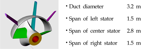
Configuration of Crown Duct
Crown Duct(CD) is designed to reflect the stern vortices in the condition of the propeller rotation. This reflecting flow may reduce the wake near propeller tip and contribute to increase the equality of wake field, which may lead to a gain in propulsive efficiency.
3. Theoretical Calculation
Computational Fluid Dynamics (CFD) is widely used in the ship design process. In particular during the initial design stage CFD has become an important tool. It enables the designer to evaluate a larger number of hull alternatives and thereby a better optimized and reliable design before the final validation. It is true that not only for new buildings but also for existing ships and retro fitting of ship energy saving devices. The tough competition on the shipbuilding market creates high demands on short lead times and competitive designs. This must be met by developments of effective CFD tools and integration with CAD.
CFD code makes cost down for the evaluation and prediction of performance of ship. Comparative theoretical calculation has been performed by CFD code of Shipflow for two different designs of Crown Duct configured as shown in Fig. 3.
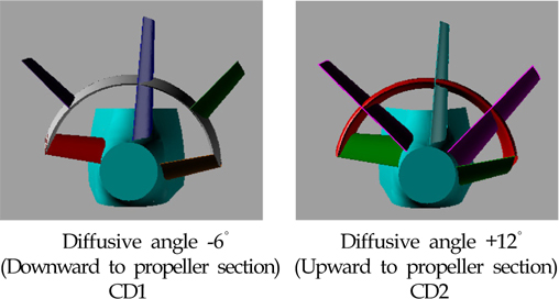
Two different design of Crown Duct
Grid used for the calculation are as follows and shown in Fig. 4.
10 Component grids
Total number of cells 4.9×10⁶
Grids of Crown Duct
The main Particulars of ship which has been simulated for the resistance and propulsion performance at design speed is shown in Table 1.
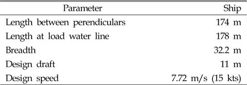
Main Particular
3.1 Resistance Calculation Result
Resistance calculation results are compared in Table 2.

Comparison of resistance components
3.2 Self Propulsion Calculation Result
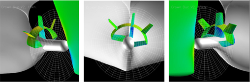
Self propulsion calculation results are summarized in Table 3. And slight retardation of velocity by stator in upper part visualized in Fig. 6 which leads to improve wake field. Wake results are shown in Fig. 5.

Comparison of self propulsion components
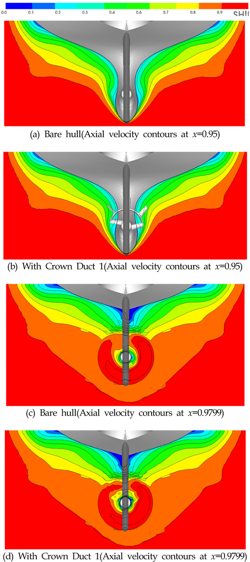
Comparisons of axial velocity contours
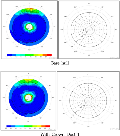
Comparisons of wakes and transversal velocities in propeller disc
4. Model Test
Model tests are carried out in the towing tank of SSPA(Lee et al., 2012).
4.1 Test facility
The towing tank has the following main particulars:
Length 260 m
Breadth 10 m
water depth 5 m
Maximum carriage speed VMAX = 11 m/s
4.2 Hull model
Ship model was manufactured in divinycell, a foam plastic material. The model scale is 1: 25.417. The model has a turbulence trip wire at station 19. The ship model with Crown Duct and propeller is shown in Fig. 7.
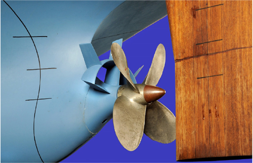
Ship model with Crown Duct and propeller
4.3 Propeller model
The propeller model is fixed, right turning, four bladed propeller with dimensions according to Table 4.
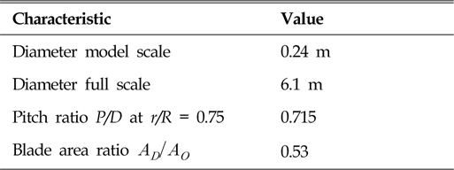
Main particulars for model propeller
4.4 Extrapolation by ITTC - 78 and Modified ITTC - 78
Without the crown duct mounted the predictions were made according to the 1978 ITTC extrapolation method.
With the crown duct mounted a somewhat modified wake scaling was used.
The method has been discussed within the 1999 ITTC and tentatively accepted for evaluation of pre-swirl stator concepts. The wake scaling presumes that tests with the same propeller but without the stator have been performed as well. The difference between model effective wake with stator and the model wake without stator is considered as a potential wake created by the stator.
The hull potential wake and the frictional wake are scaled as for the model with out stator according to the normal ITTC - 78 method, to which the stator potential part is added. The amount 0.04 represents the potential wake created by the rudder at the location of the propeller.
Thus is in the modified ITTC 1978 extrapolation the full scale wake(Lare et al., 2011).
WTsw = (two + 0.04) + (WTmwo - (two + 0.04))
*[(1 + k) CFs + ΔCFs/ (1 + k)CFm] + [WTmw - WTmwo]
where index
"W" stands for "with crown duct"
"wo" stands for "without crown duct"
"m" stands for "model"
"s" stands for "ship scale"
"T" stands for "thrust identity"
The form factor is based on the case without crown duct.
4.5 Result of model test
The results of model tests are compared in Table 5 for full load condition and in Table 6 for ballast condition. The PD (kW) values are a ship trial prediction of SSPA.

At Full load condition

At Ballast condition
4.6 Comparison of CFD calculation results with the result of model test
Comparative results of CFD calculation with model test ones are shown in Table 7. CFD Code “Ship Flow” is evaluated as applicable to the calculation of performance of ships with appendages.
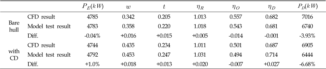
Comparison of CFD calculation results with the result of model test
5. Conclusions
Crown duct has been developed to recover the energy loss by improving propeller induced pre-rotating flow.
The model test result which is carried out in the towing tank shows that the wake factor(1-w) decreased up to considerable level.
Decreased wake factor supposed to be caused by reflecting flow generated from stator fins combination with semi-duct. Propeller revolution decreased at same thrust condition due to the decreased wake factor, and propulsive efficiency increased.
Resultantly, efficiency gain attained 4.4% at full load condition and 6.9% at ballast condition.
Theoretical calculation results in Table 7 shows possibility to be a useful tool in initial stage of design for ship energy saving device.
Acknowledgements
This study was supported by research funds from Chosun University, 2012.
References
Asaumi. T., Ikeda. T., Tamashima. M., Shinohara. H., 2006. Effectiveness of an Energy Saving Device ‘Friend Fin’, Conference Proceedings. The Japan Society of Naval Architecture and Ocean Engineering, 3, 261-264.
Asaumi. T., Ikeda. T., Tamashima. M., Shinohara. H.. Effectiveness of an Energy Saving Device ‘Friend Fin’ In : Conference Proceedings. The Japan Society of Naval Architecture and Ocean Engineering; 2006. 3p. 261–264.Lare, T.G., Jensen, S.R., 2011. Chosun 50K Tanker with Crown Duct. The Model Test Report of SSPA.
Lare T.G., Jensen S.R.. Chosun 50K Tanker with Crown Duct. The Model Test Report of SSPA 2011.Lee, J.T., Kim, M.C., Suh, J.C., Kim, S.H., Choi, J.K., 1992. Development of a Preswirl Stator-Propeller System for Improvement of Propulsion Efficiency : a Symmetric Stator Propulsion System. Transactions of the Society of Naval Architects of Korea, 29(4), 132-145.
Lee J.T., Kim M.C., Suh J.C., Kim S.H., Choi J.K.. Development of a Preswirl Stator-Propeller System for Improvement of Propulsion Efficiency : a Symmetric Stator Propulsion System. Transactions of the Society of Naval Architects of Korea 1992;29(4):132–145.Lee, J.T., Kim, M.C., Van, S.H., Kim, K.S., Kim, H.C., 1994. Development of a Preswirl Stator Propulsion System for a 300K VLCC. Transactions of the Society of Naval Architects of Korea, 31(1), 1-13.
Lee J.T., Kim M.C., Van S.H., Kim K.S., Kim H.C.. Development of a Preswirl Stator Propulsion System for a 300K VLCC. Transactions of the Society of Naval Architects of Korea 1994;31(1):1–13.Lee, K.J., An, J.S., 2012. Development of Complex Energy Saving Device. Journal of Ocean Engineering and Technology, 26(3), 1-5.
Lee K.J., An J.S.. Development of Complex Energy Saving Device. Journal of Ocean Engineering and Technology 2012;26(3):1–5. 10.5574/KSOE.2012.26.3.001.Lee, K.J, An, J.S. Yang, S.H., Park, H.J., Lim, Y.J., 2012a. Development of own Energy-Saving Device for SPP. The Research Report of Chosun University.
Lee K.J, An J.S., Yang S.H., Park H.J., Lim Y.J.. Development of own Energy-Saving Device for SPP. The Research Report of Chosun University 2012.Lee, K.J, An, J.S., Yang, S.H., 2012b. A study on the Development of Energy-Saving Device ‘Crown Duct’. Jornal of Ocean Engineers and Technology, 26(5), 1-4.
Lee K.J, An J.S., Yang S.H.. A study on the Development of Energy-Saving Device ‘Crown Duct’. Journal of Ocean Engineering and Technology 2012;26(5):1–4. 10.5574/KSOE.2012.26.5.001.