Engagement-Scenario-Based Decoy-Effect Simulation Against an Anti-ship Missile Considering Radar Cross Section and Evasive Maneuvers of Naval Ships
Article information

Abstract
The survivability of a naval ship is the ability of the ship and its onboard systems to remain functional and continue a designated mission in man-made hostile environments. A passive decoy system is primarily used as a weapon system for improving the survivability of a naval ship. In this study, an engagement scenario-based simulation program was developed for decoy effectiveness assessments against an anti-ship missile (ASM), which tracks a target with sea-skimming and active radar homing. The program can explain the characteristics of a target ship, such as the radar cross section and evasive maneuvers, as well as the operational performance of the onboard decoy system, the guidance method of the ASM, and the engagement environment’s wind speed and direction. This paper describes the theory and formulations, configuration, and user interface of the developed program. Numerical examples of a decoy effect assessment of a virtual naval ship against an ASM are presented.
1. Introduction
The survivability of a naval ship is the ability of the ship and its onboard systems to remain functional and continue a designated mission in man-made hostile environments. The survivability can be categorized using three sub-parameters: susceptibility, vulnerability, and recoverability. The total survivability can be assessed combining the probability measures of the sub-parameters (Kim and Lee, 2014). Susceptibility is the probability of not avoiding being hit by threats like anti-ship missiles (ASMs) and depends on the performance of threats and anti-air warfare (AAW) systems against them, as well as their signature characteristics.
The signatures of naval ships, such as the radar cross section (RCS), infrared (IR) signature, and visual signature, directly influence the susceptibility to threats. Particularly, RCS of a target ship is a factor for determining the performance of passive or active decoy systems for onboard soft-kill warfare against ASMs that use active radar homing for targeting and tracking. The decoy effectiveness is used as an index for the performance of passive decoy systems. A cumulative Gaussian distribution model has been used as a simple tool for decoy effectiveness assessment (An and Seo, 2015) but cannot explain the variation in RCS and performance of a decoy system for various engagement scenarios.
There have been studies on engagement scenario-based simulations (TTI, 2002; Kumar, 1990; Manji et al., 2002). Chapman and Benke (2000) described a ship-to-air defense model (SADM) for susceptibility assessment in engagement environments, which includes soft-kill ability modeling with active decoys, chaff, and jammers; hard-kill ability modeling with missiles, guns, and fire-control systems; and a command-and-control system to track targets and coordinate soft-kill and hard-kill responses. Dan et al. (2016) presented a modeling and simulation (M&S) technique for a decoy system and its countermeasure capability against ASMs. Lukenbill (1990) and Swee (2000) simulated a target aircraft in an anti-air missile engagement scenario based on a state-space model and various guidance methods. Poulos (1994) studied anti-air warfare for a small navy group in defensive scenarios. Regarding the decoy effect, Seo et al. (2012) estimated the dynamic behavior and the corresponding RCS of decoy clouds in an engagement environment with wind conditions. Kim (2020) introduced a framework on a decoy effect simulation against an ASM to consider the RCS and tactical diameter of warships.
In this research, an engagement scenario-based simulation program named ASMD/RCS (ASM Defense/RCS) was developed for decoy effectiveness assessments. This program was implemented in MATLAB/Simulink with the assumption that ASMs are the sea-skimming type and use an active radar homing for targeting and tracking (Kim, 2020). The theory and formulations were obtained from Swee (2000). ASMD/RCS can explain the RCS and evasive maneuvers of a target ship, the operational performance of an onboard passive-type decoy system, the tracking scheme of ASMs, and engagement environments, including the wind speed and direction. This paper describes details of the developed program, the theory and formulations, configuration, the scenario designation, and the user interface. A decoy effectiveness assessment of a virtual naval ship is presented as a numerical example.
2. Theory and Formulations
Countermeasures with a decoy system are a general means of avoiding being hit by ASMs. Traditionally, a passive-type decoy system has been used, which is a soft-kill method of guiding ASMs to a fake target that is generated with a decoy cloud instead of the real target ship (Fig. 1). The decoy effectiveness depends on the RCS characteristics of the target ship and the decoy system. Generally, the higher the difference in RCS level is between the target ship and the decoy, the lower the hit probability is. However, the characteristics of the ship, decoy, and engagement environments collectively influence the probability. Examples are the evasive maneuver and RCS pattern of the target ship, the deploying scheme (range and direction) and RCS of the decoy, the dynamic performance of the ASM, and environmental conditions, such as the wind speed, direction, etc. In this study, these characteristic parameters were considered for the decoy effect simulation in a more realistic engagement scenario.
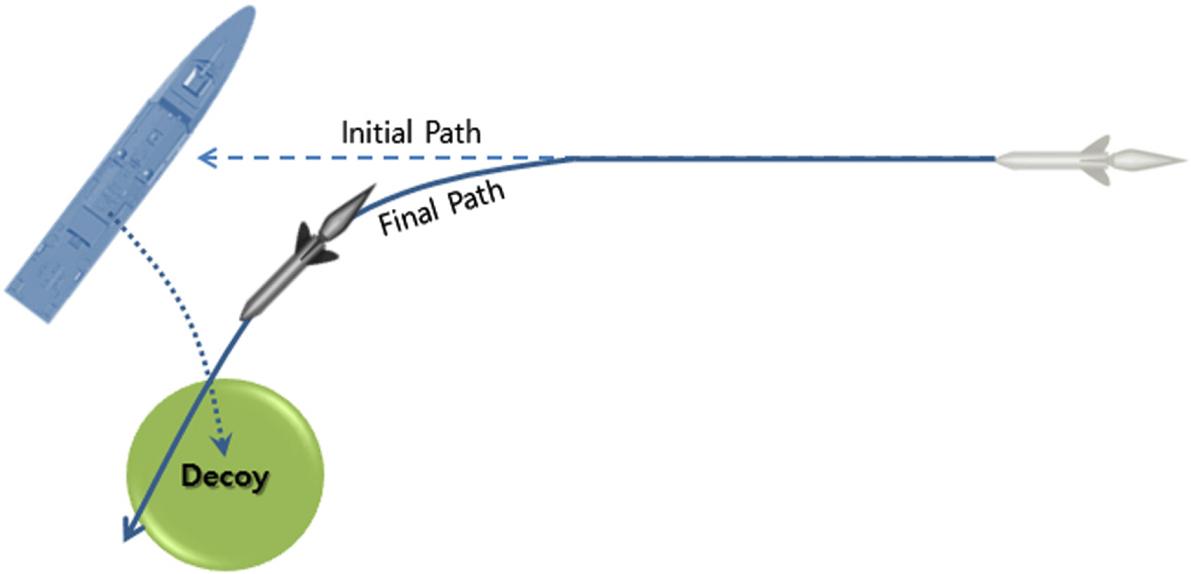
Concept of soft-kill against ASMs using passive-type decoy system
2.1 Target Ship Dynamics
The decoy effectiveness against ASMs depends on the evasive maneuvers of the target ship, which are based on the turning radius of the ship, as shown in Fig. 2. In general, the turning radius of the ship depends on the rudder angle and the instantaneous moving speed. In this study, however, the turning radius was calculated in meters with Eq. (1).
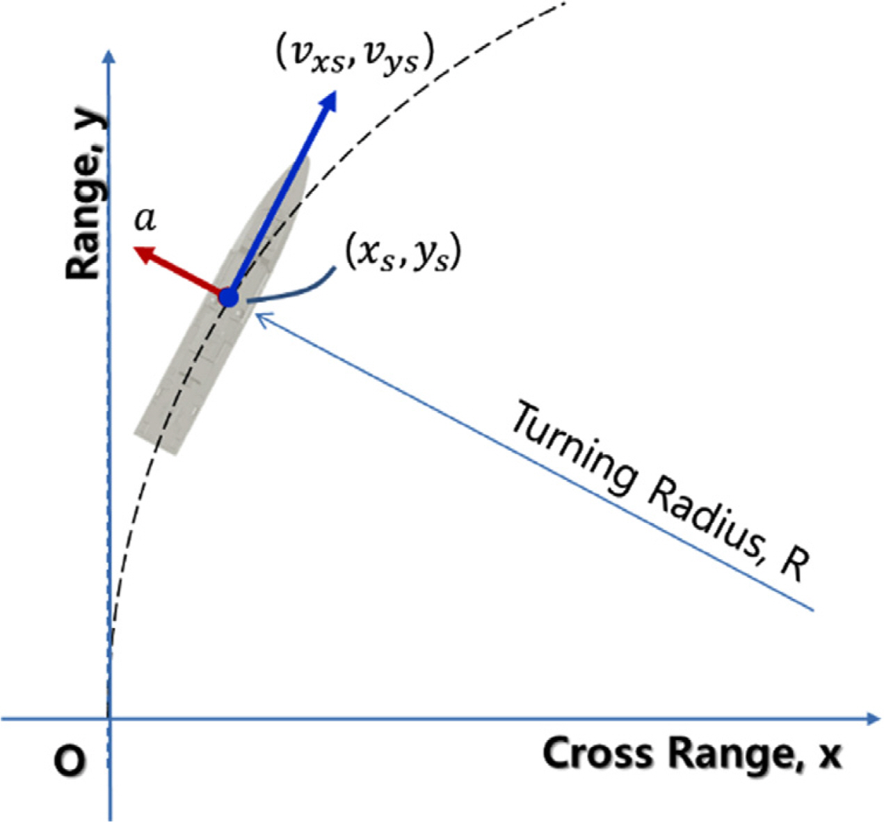
Turning radius of the target ship for evasive maneuver against ASMs
The target ship dynamics is implemented with the state-space equation below (Swee, 2000) based on the coordinate system in Fig. 2:
2.2 Target Ship RCS
The inherent RCS pattern of the target ship influences the decoy effect on ASMs. The RCS pattern of the target ship varies with the azimuth angle, as shown in Fig. 3, which means that the RCS level also changes with the approach angle of the ASM, and the decoy effect varies with it as well. The predefined RCS pattern of the target ship was used to calculate the decoy RCS value of the azimuth angle corresponding to the ASM approach.
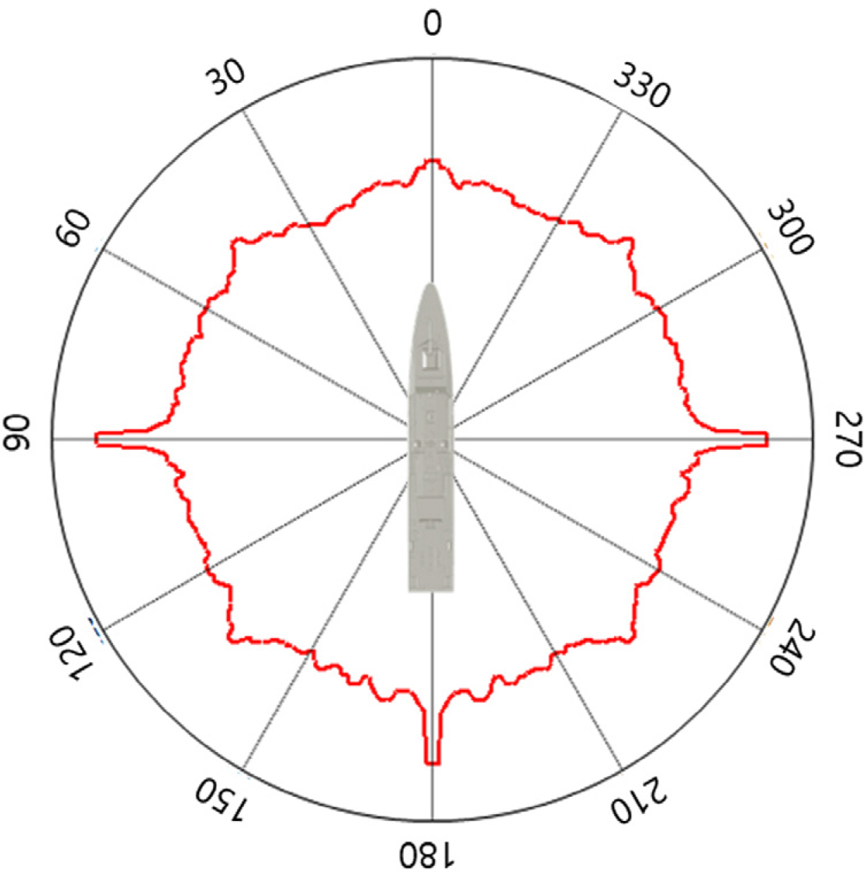
RCS pattern of the target ship with azimuth angle
2.3 ASM Dynamics
The ability of an ASM to intercept a target ship mainly depends on the guidance method. Two main types of guidance methods can be employed: proportional navigation (PN) and command to line of sight (CLOS). PN is the most widely used homing guidance law and seeks to null the line-of-sight (LOS) angle rate by making the missile turn rate directly proportional to the LOS rate. CLOS uses only the angular coordinates between the ASM and the target ship, and the ASM is made to be in the LOS between the launcher and target. Any deviation of the missile from this line is corrected.
CLOS has inherent range limitations due to its sensitivity to angular tracking errors between the launching station and the ship target. PN is self-homing and relies on an on-board seeker to provide the target’s LOS information directly, so it does not suffer from the range limitations encountered by CLOS (Swee, 2000). 2-dimensional missile dynamics was simulated by assuming an engagement scenario where the target ship does evasive maneuvers against sea-skimming ASMs that employ a PN homing law when tracking the ship target (Fig. 4).
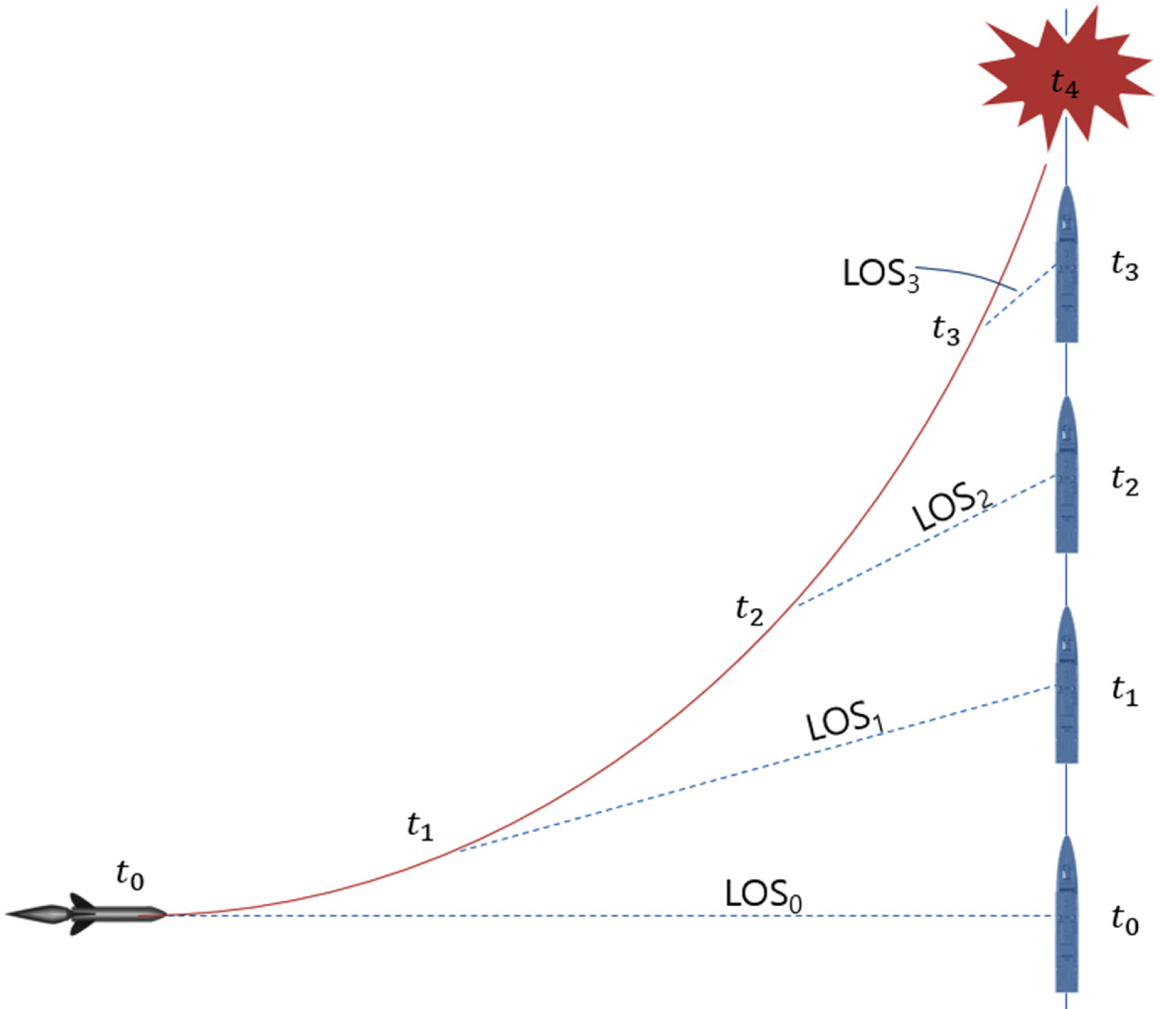
Proportional navigation to intercept the ship target
Similarly to the target ship, the ASM dynamics can be implemented with the state-space equation below with the coordinate system in Fig. 5:
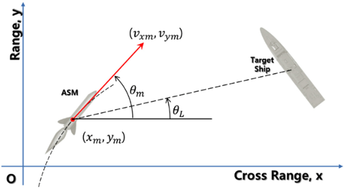
ASM guidance to the target ship
2.4 Decoy Dynamics
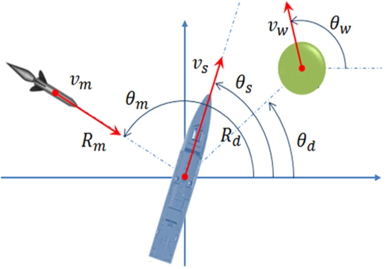
The decoy dynamics is a complex problem that is influenced by the engagement environment, including the wind speed and direction. Therefore, the problem should be simplified for convenience in the simulation. This study assumes that the decoy operates as follows: (1) launching to the direction θd in rad and deploying at the range Rd in m, (2) forming a decoy cloud and retaining its size, and (3) moving at the wind speed vw in m/s along the wind direction θw in rad, where the decoy has an omni-directional scatter, and the RCS level is kept constant during the simulation (Fig. 6).
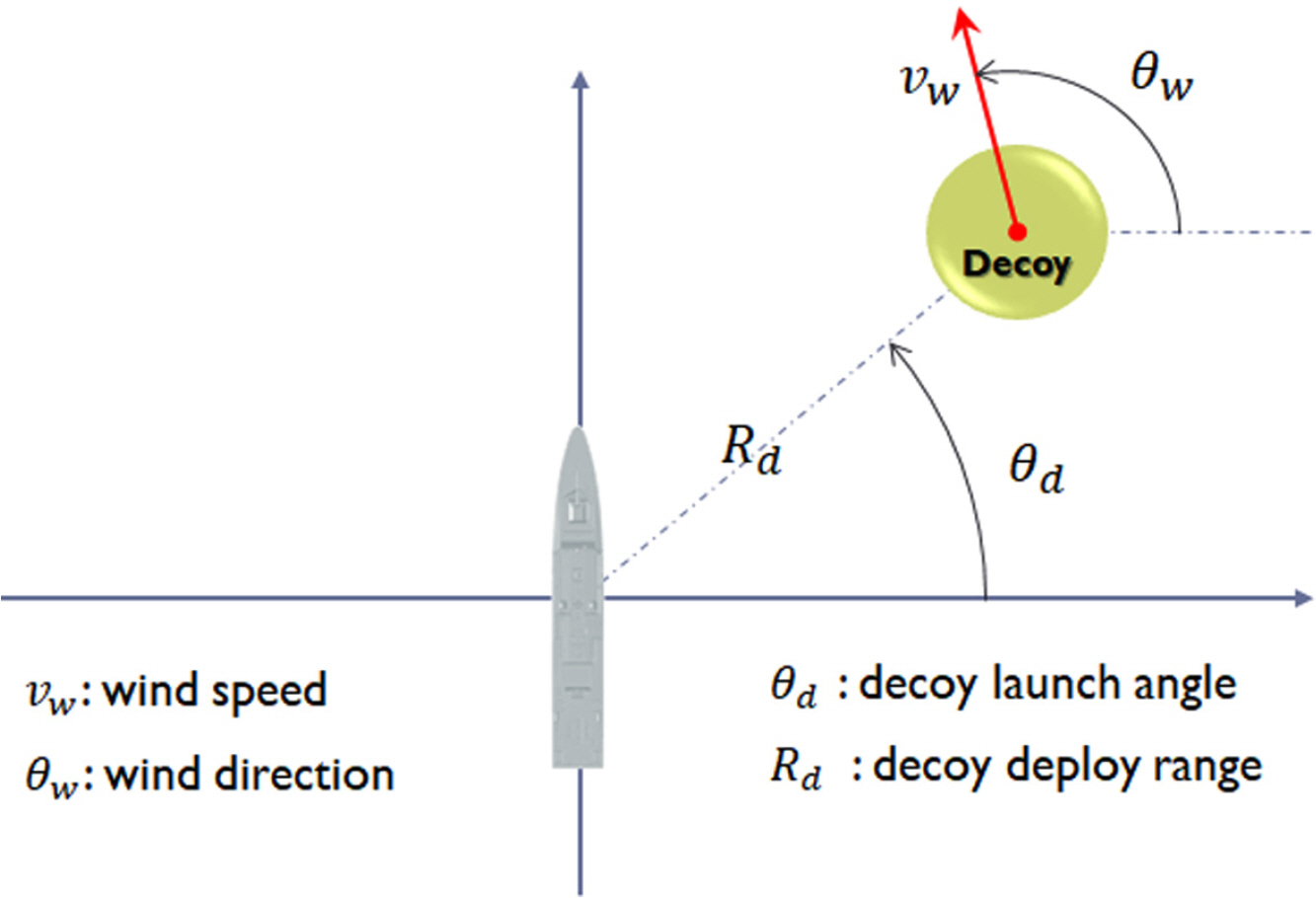
Geometry of decoy dynamics
2.5 Equivalent Scattering Center Targeting
The RCS of the target ship can be represented with a scattering source point called a “scattering center” in the far field, which is when the target ship is electromagnetically far enough from the ASMs. Interestingly, in an engagement environment, an ASM intercepts the virtual scattering center, not the real target ship (Fig. 7(a)). Therefore, when the target ship deploys a decoy with the intended RCS level to the offboard range and direction, the scattering center moves along the target-to-decoy line (Fig. 7(b) and Fig. 7(c)). As a result, the LOS moves, and the susceptibility changes. The larger the decoy RCS is, the further the scattering center is from the target ship, and the lower the susceptibility is to the ASM.

Scattering center position change by decoy RCS level: (a) no decoy, (b) small decoy (w/ low RCS), and (c) large decoy (w/ high RCS)
Referring to the coordinate system in Fig. 8, this study estimates the RCS level σsc in dBsm and position (xsc, ysc) in m of the equivalent scattering center, which is distinguished from that of the target ship using Eq. (5) and Eq. (6), respectively:
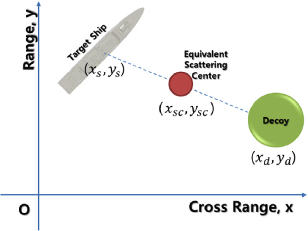
Equivalent scattering center position
3. ASMD/RCS
ASMD/RCS was implemented using the theory and formulations presented in the previous section. ASMD/RCS can consider the performance of the target ship and the ASM, the engagement environments, and the way to simulate the decoy effectiveness (Fig.9).
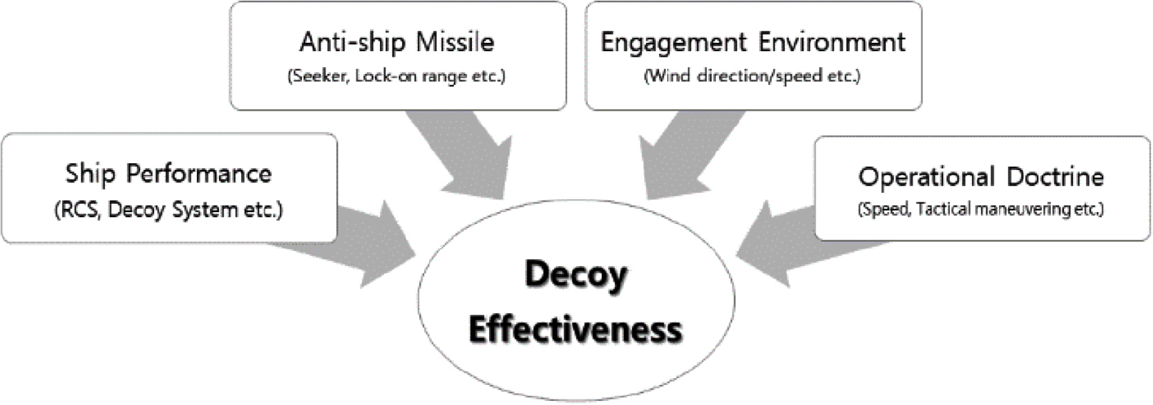
Considerations of ASMD/RCS for decoy effectiveness assessment
The program consists of four blocks, as shown in Fig. 10: a decoy block, guide block, target ship block, and missile block. The decoy block includes the decoy performance and dynamics (RCS, deployment range and direction, and movement wind and its direction). The guide block implements the ASCM’s targeting and tracking with the missile-to-target guidance algorithm. The target ship block includes the target ship performance and status (the initial position, RCS, speed, direction, and evasive maneuver of the target ship). Finally, the missile block simulates the ASM dynamics.

ASMD/RCS block configuration: (a) ASMD/RCS, (b) decoy block, (c) guide block, (d) target ship block, and (e) missile block
Fig. 11 shows the program’s user interface and a plot of the simulation results. The interface is composed of 13 input boxes for simulation parameters and two buttons for program execution and a result plot. The plot displays trajectories of the ASM, the target ship, and the decoy, as well as text-based results, such as the missing distance and time to intercept. The term “missing distance” means the closest point of approach (CPA) synchronized from the center of the target ship to the ASM trajectory at the moment “time of intercept” (Fig. 12). This judges whether the target ship will be intercepted by the ASM or not by assessing whether the resultant missing distance in m exceeds the pre-defined threshold. This study uses two times the length of the target ship as a threshold.
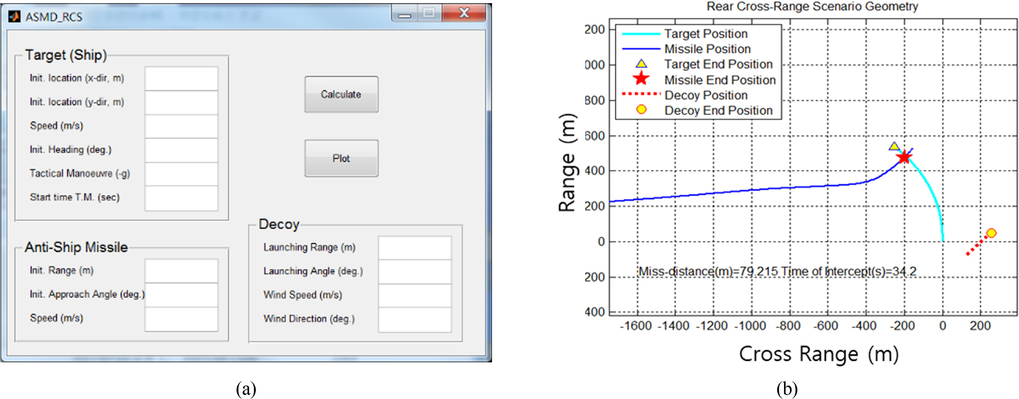
ASMD/RCS (a) user interface and (b) engagement trajectory viewer
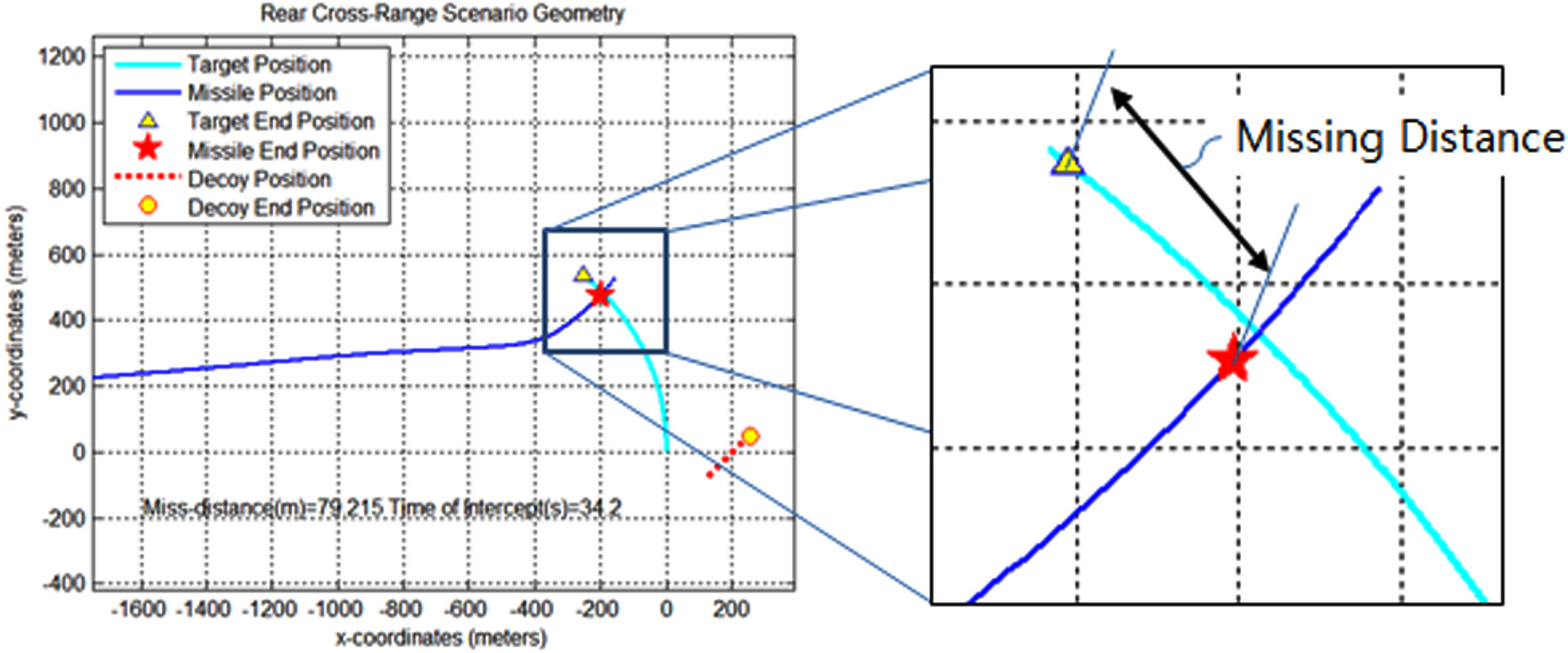
Definition of missing distance
4. Numerical Examples
4.1 Engagement Scenarios
Decoy effect simulations were conducted using ASMD/RCS in some engagement scenarios. Following the input parameter symbols in Fig. 13, the engaging speed vm, lock-on range Rm, and approach angle θm of the ASM were set to Mach 0.9 (∼306 m/s), 8 km, and 180 degrees, respectively. The centripetal acceleration was limited to 20-g. The length of the target ship was 45 m, and the corresponding missing distance threshold was two times the target ship length. The ship speed vs was 35 knots (∼18 m/s), and the RCS pattern σs is shown in Fig. 14. The decoy is launched toward any direction θd and deployed at a range Rd of 150 m.
Input parameter for engagement simulation
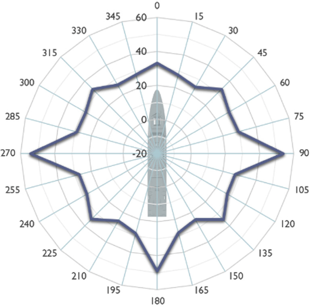
RCS pattern of the target ship for engagement simulation
The RCS level σd of the decoy varies (27, 30, 33, 37, and 40 dBsm, which correspond to 500, 100027, 30, 33, 37, and 40 dBsm, which correspond to 500, 2000, 5000, and 10000 m2, respectively). There is only one chance of launching a decoy, and an evasive maneuver is done during the engagement at the same time as the ASM lock-on. The simulation designated three engagement scenarios with varying g-value
4.2 Simulation Results
Fig. 15 shows simulation results for the scenarios for when the decoy launching direction θd is 135 degrees and the RCS of the target ship is 40 dBsm (10,000 m2). The target ship survives when doing no evasive maneuver (0-g), but it is intercepted when doing the port-side (0.05-g) and starboard-side (−0.05-g) evasive maneuvers. In starboard-side evasive maneuvers, the primary deception succeeds, but the ship is eventually intercepted. This means that ASMD/RCS can simulate complicated engagement scenarios more realistically.

Engagement simulation results when the decoy launching direction θd is 135 degrees: (a) no evasive maneuver (0-g), (b) port-side evasive maneuver (0.05-g), and (c) starboard-side (−0.05-g) evasive maneuver
Fig. 16 shows polar plots of the simulated missing distance versus the decoy launching direction θd for the scenarios. The curves present the simulated missing distance with respect to the RCS level σd of the decoy (27 dBsm (500 m2), 30 dBsm (1,000 m2), 33 dBsm (2,000 m2), 37 dBsm (5,000 m2), and 40dBsm (10,000 m2)). The dotted red reference line shows the pre-defined threshold (two times the target ship length: 90 m).
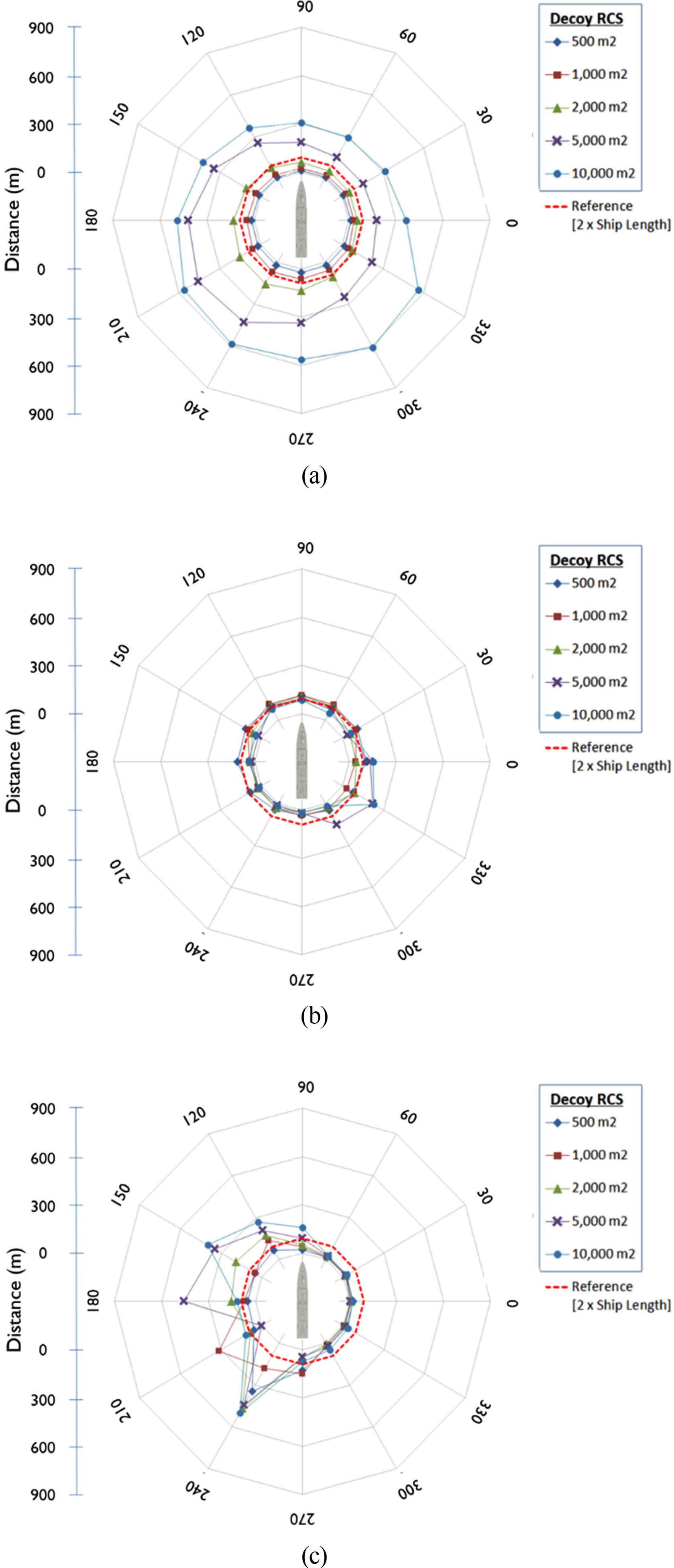
Simulated missing distance versus the decoy launching direction θd in engagement scenarios: (a) no evasive maneuver (0-g), (b) port-side evasive maneuver (0.05-g), and (c) starboard-side evasive maneuver (−0.05-g).
With no evasive maneuver (0-g), the missing distance increased as the decoy RCS increased. When the decoy RCS levels were above 37 dBsm (5,000 m2), the target ship was hit less overall. When the decoy of 33 dBsm (2,000 m2) was launched between 150 degrees and 300 degrees, the target ship was hit less. When the decoy RCS level was 40 dBsm (10,000 m2), wind reduced the susceptibility of the 300-degree and 330-degree decoy deployments.
For the port-side evasive maneuver (0.05-g), the decoy effect was minimal in general. An evasive maneuver works unfavorably in terms of susceptibility to ASMs. The decoy was moved by the wind along the 45-degree direction, which slightly increased the susceptibility of the decoy deployments at 0 degrees, 300 degrees, and 330 degrees. For the starboard-side evasive maneuver (−0.05-g), the missing distance increased as the decoy RCS increased. Simultaneously, the susceptibility was reduced when the decoy was deployed toward 120 to 240 degrees. It was confirmed that the ASMD/RCS program was successfully implemented and could be applied to decoy effect simulations of various engagement scenarios.
5. Conclusions
An engagement scenario-based simulation program named ASMD/RCS was developed based on a state-space model to assess the decoy effect on a sea-skimming ASM using an active radar homing for targeting and tracking. The programs can consider the RCS and tactical maneuvers of the target ship, the onboard decoy system performance, the ASM guidance algorithm, and the engagement environment’s wind speed and direction. The program provides a user interface for input parameters, executing the program, and plotting results. Numerical simulations of virtual engagement scenarios were conducted for various RCSs and launching directions of the decoy. The results showed that the input parameter variations in engagement environments influence the decoy effect. It is expected that the program could be practically used for assessing a decoy system’s performance for naval ships.
Acknowledgements
This research was supported by Tongmyong University Research Grants 2019 (2019A020-1).