1. Introduction
Mission and operating environments are becoming more diverse and complex as the demand for operating autonomous underwater vehicles (AUVs) in the marine sector increases (Cho et al., 2019; Kim et al., 2021). However, when AUVs perform missions, such as exploring submarine topography/resources, inspecting marine structures, and monitoring the ocean, they must be recovered after a certain period of operation for recharging and backing up data because they are not supplied with external power and communication modules, resulting in considerable ship operation and launch or recovery costs and times, while making it impossible to perform launch or recovery missions under poor weather conditions. As a result, AUVs have several limitations in terms of operating range and time (Cho et al., 2019; Cho et al., 2020a).
Underwater docking technology is one methods for addressing these problems of AUVs. The operating range and time of AUVs can be increased by installing a docking station (DS) that receives power and communication lines from the land at an arbitrary underwater location and docking the AUVs at the docking station. To guide an AUV for docking, it is essential to develop a technique to estimate the relative distance and angle between the AUV and docking station, a terminal guidance control technique to precisely guide the AUV to the docking cone, and a mission management technique to increase the mission success rate and operational stability of the AUV (Park et al., 2019). Therefore, developed maritime countries, such as the United States and Japan, have been investigating various docking methods since the 2000s, including the hooking mechanism (Fukasawa et al., 2003; Kimball et al., 2018) and cone mechanism (Hobson et al., 2007; Zhang et al., 2017). Allen (2006) attempted docking in a cone-shaped station using the AUV remote environmental monitoring units (REMUS)-100 and successfully docked 17 times out of 29 attempts (approximately 59%); however, this docking success rate needs to be improved for application in an actual system (Allen et al., 2006). Li et al. (2015) conducted a study on docking using WL3-AUV in a water tank environment, succeeding in docking at a rate of approximately 80% using a camera and light-emitting diode (LED). However, they reported that problems such as image processing and LED brightness control would need to be resolved before applying in an actual sea environment (Li et al., 2015).
A mission management technique based on various data, such as the AUVŌĆÖs status information and information from multiple types of guidance sensors, is required to increase the success rate for docking an AUV in the actual sea environment. As the types of sensors increase, the hardware and software systems of the AUV become more complex, with different algorithms required to be used in combination. The mission management technique uses information from the sensors mounted on the AUV to continuously manage the status, location, attitude, and mission performance status of the AUV, while aiming to increase the efficiency and stability over the operating time and path. As a relevant previous study, Wolf et al. (2017) successfully demonstrated the execution of missions, such as reconnaissance, tracking, and inspections, by applying the control architecture for robotic agent command and sensing (CARACaS) in a number of unmanned surface vehicles (USVs). However, it appears that the application in an underwater system still needs to be supplemented because the study is limited to USVs with readily available data communication, with the system only allowing a restrictive intervention by the operator in emergency situations. Albiez et al. (2010) applied the mission management architecture developed for the AUV ŌĆśAVALONŌĆÖ equipped with six thrusters and successfully performed the exploration and tracking missions for underwater pipelines, but reported that further research would be necessary on the application in complex missions and systems. Barrouil and Lemaire (1999) developed the general-purpose programming and execution monitoring of autonomous systems (ProCoSA) and verified its suitable application in the AUV system through simulation; however, additional validation is required for actual underwater AUV systems. In addition, Pinto et al. (2012) designed and demonstrated a mission planning architecture for light AUV (LAUV)-Seacon AUV using teleo-reactive executive (T-REX) and confirmed that, although there was a problem in selecting the optimal sequence of actions, the architecture worked properly. Xue and Lekkas (2020) simulated T-REX and the robot operating system plan (ROSPlan) and compared and analyzed the performances, confirming their adequate operation despite each having its own strengths and weaknesses. Papadimitriou and Lane (2014) simulated a mission planning algorithm for performing a mine countermeasure (MCM) mission using a planning domain definition language (PDDL), confirming that the mission was successfully performed in a dynamic environment. An artificial intelligence (AI) planner of this type can reliably perform a given mission; however, it requires time and cost for initial installation and integration with existing systems. In addition, owing to hardware and software limitations in the manufactured AUV, the algorithm was not applied to this mission management technique.
In most of these existing studies, mission management systems have been developed with similar architectural structures, while the stability, efficiency, and scalability considering the performance of missions were emphasized. However, studies are being conducted on the use of USVs, where operators are allowed to intervene under certain conditions. In the case of AUVs, no external intervention is allowed during a mission, owing to the nature of the environment, making application and verification in an actual system difficult. In addition, as the demand for performing various missions increases, the AUV system is gradually becoming more complex, highlighting the significance of a relevant mission management technique.
In this study, we propose a mission management technique for the underwater docking of an AUV using multiple sensors. The proposed algorithm was applied to an AUV equipped with multiple guidance and inertial sensors to verify the operational performance on land and in an actual sea environment. The unmanned vehicle is operated with a single thruster and four control panels, and has the characteristics of a non-holonomic system (Kim et al., 2018). In the proposed mission management technique, the feasible initial area (FIA) level, event level, and global path (GP) command were defined to reflect the operating environment and docking scenarios of the AUV. To effectively utilize the multiple sensors and increase the docking success rate, the FIA level was defined in three stages considering the characteristics of the AUV and mounted sensors. In addition, the event level was specified based on the hardware and mission performance status of the AUV to ensure the stability in the mission performance of the AUV. Finally, the behavior of the AUV, depending on the situation, was defined by the GP command to allow autonomous responses to various situations that could occur during docking. Experiments were conducted on land and in the actual sea environment to verify the developed algorithm and confirm adequate operation based on the situation.
In Section 2 of this paper, the AUV and docking station used to validate the performance of the mission management technique are described. In Sections 3 and 4, the proposed mission management technique and performance verification experiments are described. Finally, the conclusions are summarized in Section 5.
2. Test-bed System
2.1 AUV and Docking Station
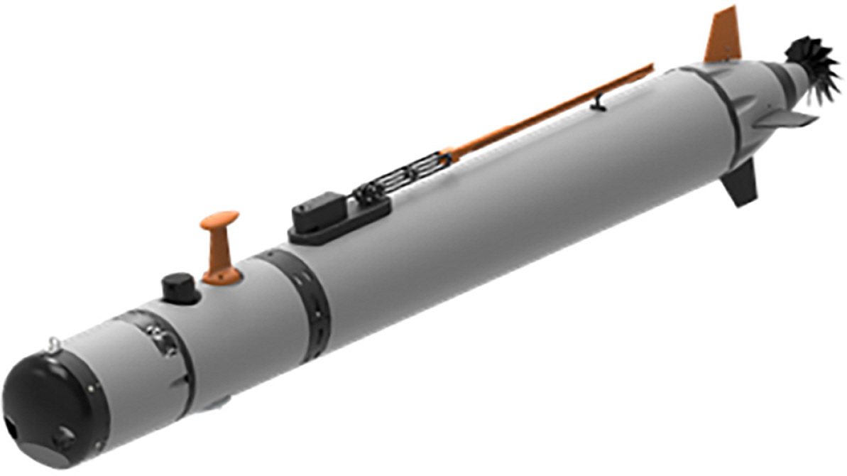
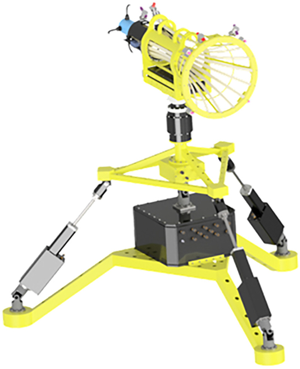
An AUV and a docking station were constructed, as shown in Figs. 1 and 2, to verify the performance of the underwater docking technique. The AUV is designed in the shape of a torpedo and consists of a bow, hull, and stern. The bow is equipped with guidance sensors, such as an inverted ultrashort baseline (iUSBL) transponder and forward-looking sonar (FLS), as well as navigation sensors, such as an inertial measurement unit (IMU), Doppler velocity log (DVL), and digital compass (DCS). The hull houses an electric unit, a battery, communication equipment, among other components, while the stern houses a driving unit, including one thruster and four rudders. The AUV has the characteristics of an underactuated system, i.e., a non-holonomic system that must implement six degrees of freedom using a forward-direction thrust and pitch and yaw motion controls, requiring a terminal guidance control technique, and relative distance and direction estimation technique (Li and Lee, 2009). The docking station is a device capable of charging a battery and backing up data by docking the AUV and is shaped like a cone with unidirectional access. The docking station consists of a platform, power system, control unit, and guidance unit. An acoustic Doppler current profiler (ADCP) is installed on the platform to measure the direction of currents. The control unit can control the azimuth and altitude of the platform, and the guidance unit, including an optical guidance device and iUSBL transceiver, is installed in the docking cone where the AUV is received. Using this setup, the attitude of the docking station was corrected based on the seabed terrain, with the direction of the docking cone entrance adjusted to the direction of the current flowing to improve battery operation efficiency and docking success rate of the AUV (Kim, 2019).
2.2 AUV Navigation and Control
As mentioned above, underwater docking is an essential technology to overcome the limitations of the AUV in battery capacity and underwater communication. Implementing this technology requires (1) estimating the relative distance and direction between the AUV and docking station by combining the data from multiple sensors mounted on the AUV, (2) high-precision AUV terminal guidance control, and (3) docking mission management.
Hybrid underwater navigation estimates the accurate attitude of an AUV, with a Kalman filter constructed with navigation sensors to estimate IMU, DVL, and DCS, and the linear velocity, linear acceleration, and angular velocity of the AUV. In addition, a mechanical model is built using the AUVŌĆÖs altitude information, and the location and altitude of the AUV in navigation coordinates are estimated by integrating the linear velocity, linear acceleration, and angular velocity (Choo et al., 2020). Based on the estimated location and altitude information of the AUV, the relative distance and direction to the docking station with its location inputted in advance are estimated. A robust trajectory estimation control technique is used for precise terminal guidance control of AUV. The AUV used in the experiment has nonlinear dynamics combining rigid body dynamics and hydrodynamics. With the AUVŌĆÖs underactuated system, it is difficult to directly control all state variables, with restrictions between the state variables. In addition, disturbances, such as currents, on both sides of the AUV affect the uncontrollable state variables. Therefore, an attempt has been made to estimate and compensate for the nonlinear dynamics of the AUV using the time delay estimation technique and to overcome the characteristics of the underactuated system through the design of reference error dynamics (Cho et al., 2020b). The docking mission management technique is described in detail in the following section.
3. Mission Management Technique Design
3.1 Problem Statement
The AUV must perform underwater docking missions in the absence of external monitoring and intervention. In previous studies, USVs were used to perform specific missions, such as port monitoring and reconnaissance, assuming that an operator was present to monitor the performance of missions and the status of the USVs. Decisions regarding the selection of missions and methods were made by the algorithm, but the operator was allowed to intervene in emergency situations, such as damage. However, in the case of the AUV, communication with the outside is limited, with external intervention not allowed during the mission, owing to the nature of the underwater environment. In addition, because the experimental environment is poor, verifying the performance in an actual sea environment is challenging, making it necessary to prepare for emergency situations, such as the loss of the AUV.
As the guidance accuracy of the AUV increases, multiple guidance and navigation sensors must be adequately managed and utilized. In contrast to other general missions, such as exploration, docking missions require precise location estimation and maneuver, with the AUV equipped with multiple guidance and navigation sensors. Moreover, several detection sensors are installed to check for water leaks and other conditions inside the AUV. Based on these data, the AUV and mission status should be monitored, guiding the AUV based on the situation. However, considering the vast amount of information to manage with an interrelated structure, it is difficult to respond appropriately to changes, such as system expansion or mission addition, by simply implementing the mission management concept through integrated software; the docking success rate decreases without appropriate management of the situation. In addition, considering the characteristics of each guidance sensor, the operating distance and resolution for optimal performance vary, which requires adequate management.
To address these problems, a mission management technique was implemented in this study by analyzing the operating environment and docking scenarios of the AUV and the characteristics of each guidance and inertial navigation sensor. The FIA level was defined in consideration of the characteristics of the AUV and mounted sensors, and the docking success rate was improved by effectively utilizing multiple sensors. The stability in the mission performance of the AUV was ensured by specifying the event level according to the AUV hardware and mission status. In addition, the behavior of the AUV was defined by the GP command to allow autonomous responses to various situations that could occur during docking.
3.2 Design
In this study, to implement the mission management technique for docking, the operating environment and docking scenarios of the AUV and characteristics of the navigation and guidance sensors were analyzed and classified by the FIA level, event level, and GP command. Figs. 3 and 4 show the normal or abnormal scenarios for docking the AUV. The AUV, which performs a specific mission, begins docking at the docking station or travels to an assigned point when an abnormal situation occurs, such as a missed waypoint or an abnormality in the state of the AUV, to terminate the mission or re-attempt docking.
3.2.1 FIA level
As shown in Fig. 3, the docking process of the AUV was divided into FIA stages 1 to 3. The relative distance for each stage was defined to reflect the characteristics and operating distance of the mounted guidance and inertial sensors. Based on the non-holonomic characteristics of the AUV, its attitude at the time of entering each stage was defined to increase the underwater docking success rate As shown in Fig. 4, when the AUV cannot enter a stage owing to currents, it returns to the assigned point and reattempts docking. When enteringFIA 2, the relative distance and azimuth between the AUV and docking station must be 100 m and 10┬░ or less, respectively, and the water depth must be the same. When entering FIA 3, the relative distance and azimuth must be 15 m and 5┬░ or less, respectively, and the water depth must be the same. In the FIA 2 and 3 stages, the docking success rate is calculated at each sampling time to determine whether to attempt docking. When the success rate is calculated to be less than 80%, the AUV returns to the assigned point and reattempts docking. Table 1 lists the entry conditions for each stage.
In FIA stage 1, the AUV terminates its mission at a certain location and starts homing to a pre-specified docking station. For the approach to the docking station, the AUV estimates the location using sensors, such as the inertial navigation system (INS), ultrashort baseline (USBL), and underwater acoustic modem (ATM), while control and navigation errors are allowed at a certain level. In FIA stage 2, the AUV approaches the docking station closely using the installed guidance sensors to confirm the exact location of the docking station and maintain the accurate navigation performance for increased control precision. The docking station is detected by FLS mounted on the AUV at the relative distance of approximately 100 m, with the relative distance and azimuth estimated and corrected using iUSBL at approximately 30 m for the approach to the docking station. In FIA stage 3, the AUV attempts to dock at the docking station, requiring accurate navigation performance and precise control performance. The relative distance and azimuth between the AUV and docking station are accurately estimated and guided using precise guidance sensors, such as an optical guidance device and acoustic camera mounted on the docking station. The final call for docking is made using a camera and docking switch installed on the docking station. The sensors used in each stage are turned on/off to minimize the power consumption of the AUV.
3.2.2 Event level
The status of the AUV and mission performance were checked constantly during docking to ensure the safety of the AUV and increase the docking success rate. As listed in Table 2, the event level was defined to determine the point of return or homing in an abnormal situation, as shown in Fig. 4. Depending on the degree of damage, the priority was specified in the order of ŌĆ£deadly damage,ŌĆØ ŌĆ£damage,ŌĆØ ŌĆ£return,ŌĆØ and ŌĆ£keep going.ŌĆØ ŌĆ£Deadly damageŌĆØ is a stage where a mission becomes impossible owing to damage to the thruster or major sensors, and the entire system stops and floats with its own buoyancy. A temporary safety function was added for the stability of the experiment, which prevented the AUV from diving into deep water owing to malfunction of the algorithm under development, rolled the AUV from the experiment support ship for a forced roll limit, and allowed the AUV to terminate the mission and float with its own buoyancy after a certain operation time to prevent its loss. ŌĆ£DamageŌĆØ is a stage where the AUV can be operated temporarily but must be moved quickly to an assigned point owing to problems such as leaks. The AUV is moved from the current location to the surface or start point over the shortest distance to prevent accidents, such as the loss of the AUV. ŌĆ£ReturnŌĆØ is when the AUV is rebooted or returned to the previous waypoint because the arrival conditions for each FIA level or waypoint are not satisfied. The number of attempts to return is set to one, which can be adjusted depending on the situation. ŌĆ£Keep goingŌĆØ is a stage in which all conditions of the AUV are acceptable, and the mission continues. A path is generated at the start of the docking mission; once a waypoint is reached, the next waypoint is updated. The GP command called at each event level is described in the following section.
A waypoint is considered to have been reached when Eq. (1) is satisfied. The distance between the AUV and current waypoint (distanceToFrontPoint), the distance between the AUV location and previous waypoint (distanceToRearPoint), and distance between the current waypoint and previous waypoint (distanceToBetPoint) are calculated using the Euclidean norm. cir cleSize indicates the AUV arrival radius defined at each waypoint, which can be flexibly adjusted based on the given path. The AUV is considered to have reached the waypoint when cir cleSize is greater than distanceToFrontPoint, whereas the AUV is considered to have gone past the waypoint when distanceToRearPoint is greater than distanceToBetPoint.
pass ŌĆē Condition = { true , ŌĆē distance ŌĆē To ŌĆē Front ŌĆē Point Ōēż circle ŌĆē Size false , ŌĆē distance ŌĆē To ŌĆē Rear ŌĆē Point > distanceBetPoint distance ŌĆē To ŌĆē Front ŌĆē Point = ŌĆ¢ Po s a u v ŌłÆ Po s waypoint ( ID ) ŌĆ¢ distance ŌĆē To ŌĆē Rear ŌĆē Point = ŌĆ¢ Po s a u v ŌłÆ Po s waypoint ( ID ŌłÆ 1 ) ŌĆ¢ distance ŌĆē Bet ŌĆē Point = ŌĆ¢ Po s waypoint ( ID ) ŌłÆ Po s waypoint ( ID ŌłÆ 1 ) ŌĆ¢
(1)
3.2.3 GP command
Based on the state of the FIA and event levels, the behavior of the AUV was defined as listed in Table 3. Several situations that may occur during underwater docking missions were predefined, allowing the AUV to respond to each situation according to a consistent set of rules. GP 0 is called when there is no problem during docking, GP 2 is called when the target position is reached during the mission, and GP 1 is called at the end of the mission. GP 3 and GP 4 are called when a new waypoint is generated and updated, respectively, while GP 5ŌĆō9 are called when the AUV must move to an assigned point. A new return point or state can be defined additionally.
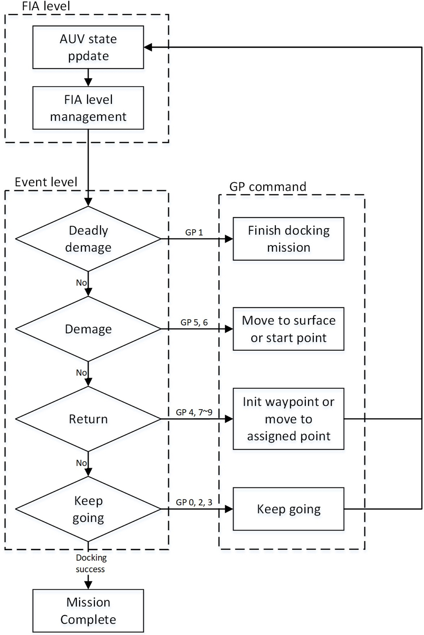
Fig. 5 shows the diagram of the mission management algorithm. The state of the AUV is updated, with the FIA level checked at every moment. In addition, the status of the AUV and mission performance are confirmed, and the corresponding GP command is called. The mission continues when GP 0, 2, 3, 4, 7, 8, or 9 is called. Finally, the mission is terminated upon successful docking.
4. Experimental Studies
Experiments were conducted on land and in the actual sea environment to verify the mission management algorithm. Algorithm stability was pre-verified by simulating the sea environment on land to minimize the risk of loss or collision that could occur in the actual sea environment and verify the interconnection between the algorithms. For the convenience of the experiment in the sea environment, a simple docking station was installed to conduct the underwater docking experiment. The simple docking station simplifies the system based on the experimental environment, consisting only a docking cone and frame that holds the docking cone, making the system lightweight for easy installation and recovery.
4.1 Ground Test
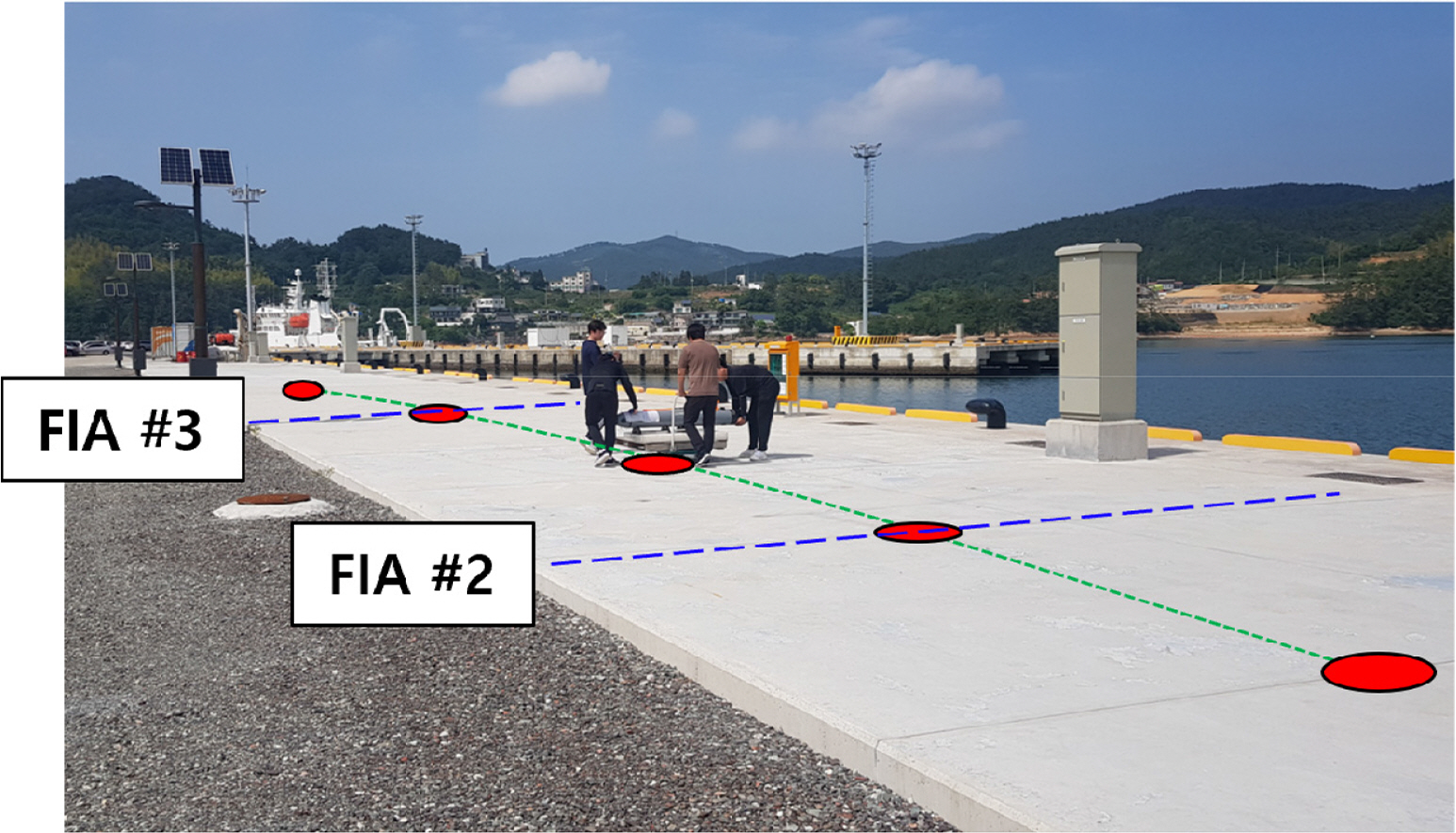
An experiment was conducted on land to verify the performance and interconnection stability of the mission management algorithm in a land environment where the safety of the AUV would be guaranteed. The results of the operational decisions according to the relative distance between the AUV and docking station and the occurrence of abnormal situations were confirmed. In the experimental method, the AUV was fixed on a trolley and manually moved along seven arbitrarily determined waypoints in a straight line, as shown in Fig. 6, to simulate a normal and an abnormal movement situation (an unreached waypoint). The location of the AUV was updated using GPS instead of INS.
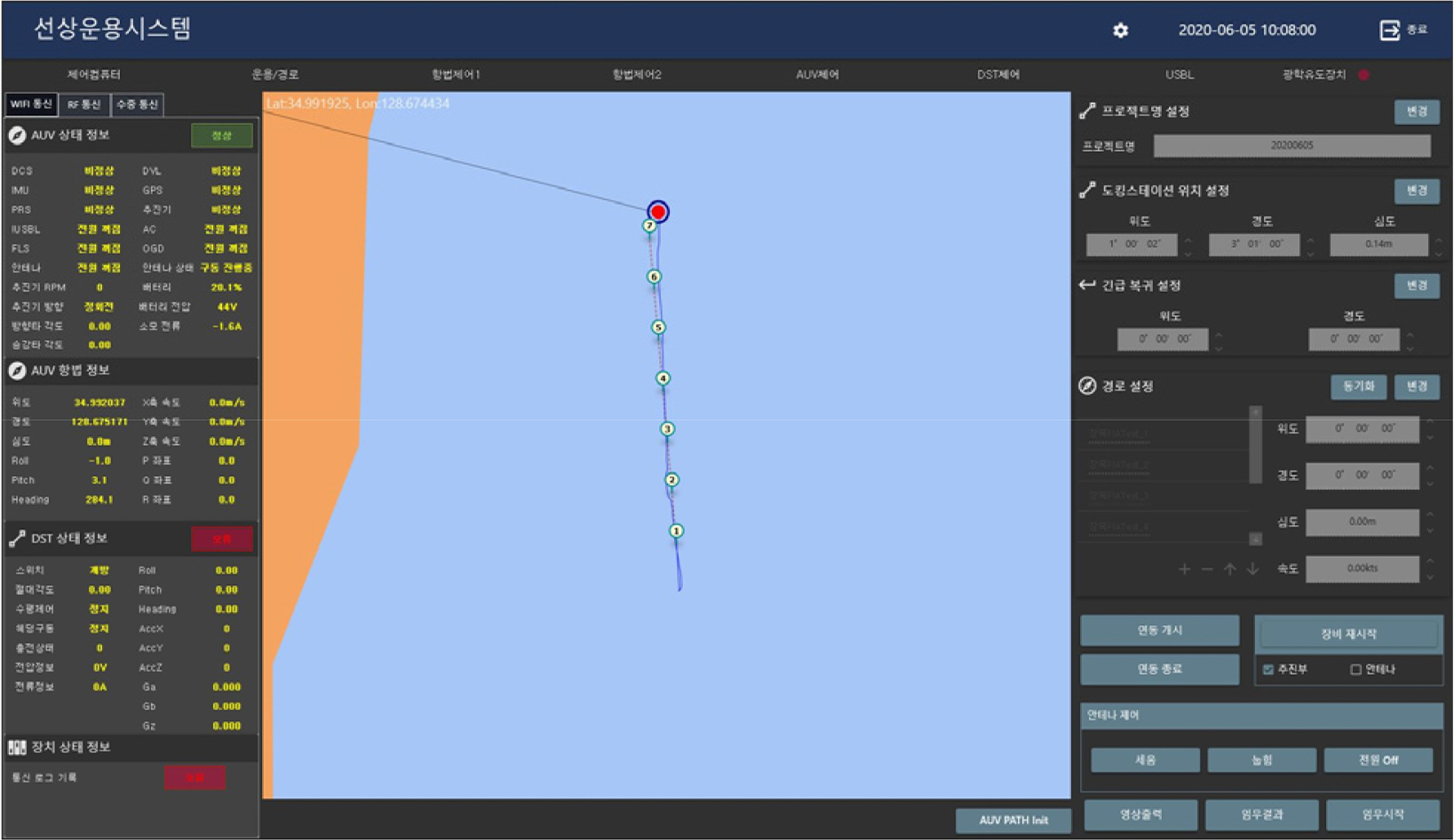
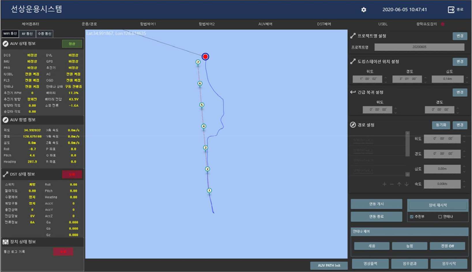
Fig. 7 shows the operation console used to confirm the set waypoints and path of the AUV movement. The figure shows that the AUV was moved appropriately along the preset path. The distance at each FIA stage was adjusted to 30 m owing to the limited test environment. The operation console is a system for controlling the AUV, where parameters, such as the movement path and control of the AUV, can bespecified, and the status can be monitored.
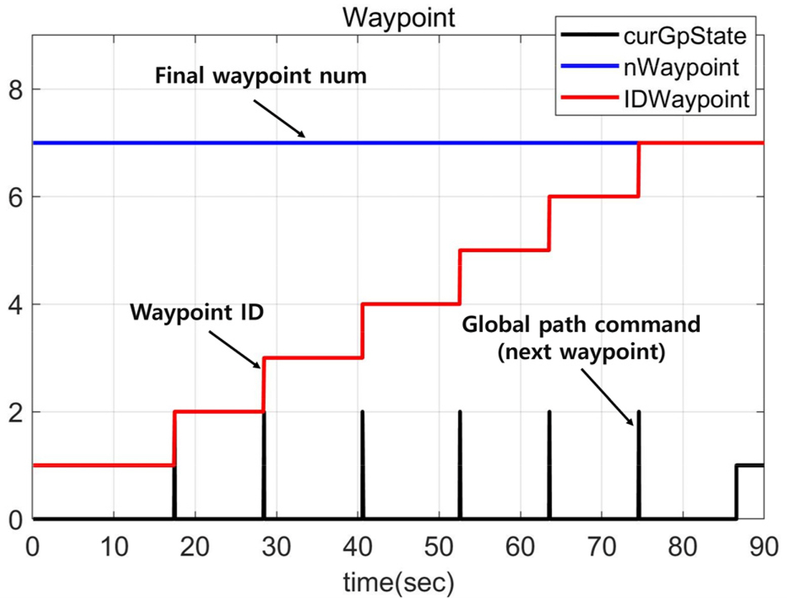
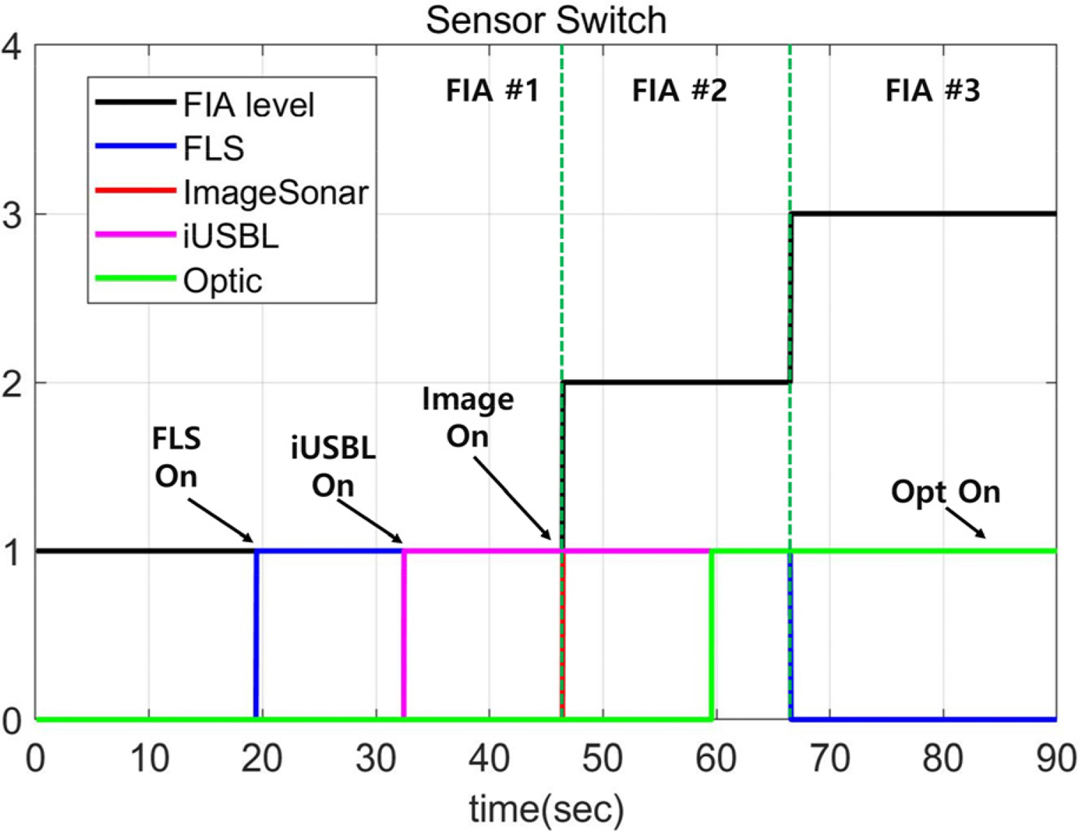
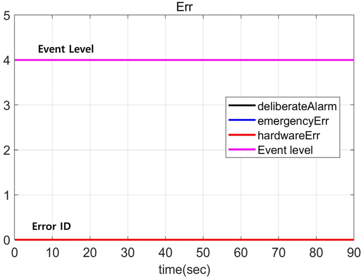
Fig. 8 shows the waypoint ID and GP command based on the distance. As the AUV passes each waypoint, GP 2 is called, and the waypoint ID is updated. Once the last waypoint is reached, GP 1 is called, and the mission is terminated. Fig. 9 shows that each sensor is turned on/off depending on the FIA level and relative distance. Fig. 10 shows the event level and error ID. DeliberateAlarm and HardwareErr correspond to the ŌĆ£deadly damageŌĆØ stage of the event level, and EmergencyErr refers to the ŌĆ£damageŌĆØ and ŌĆ£returnŌĆØ stages. Considering the AUV is operating normally along the specified path, Event 4 is called until the mission is completed.
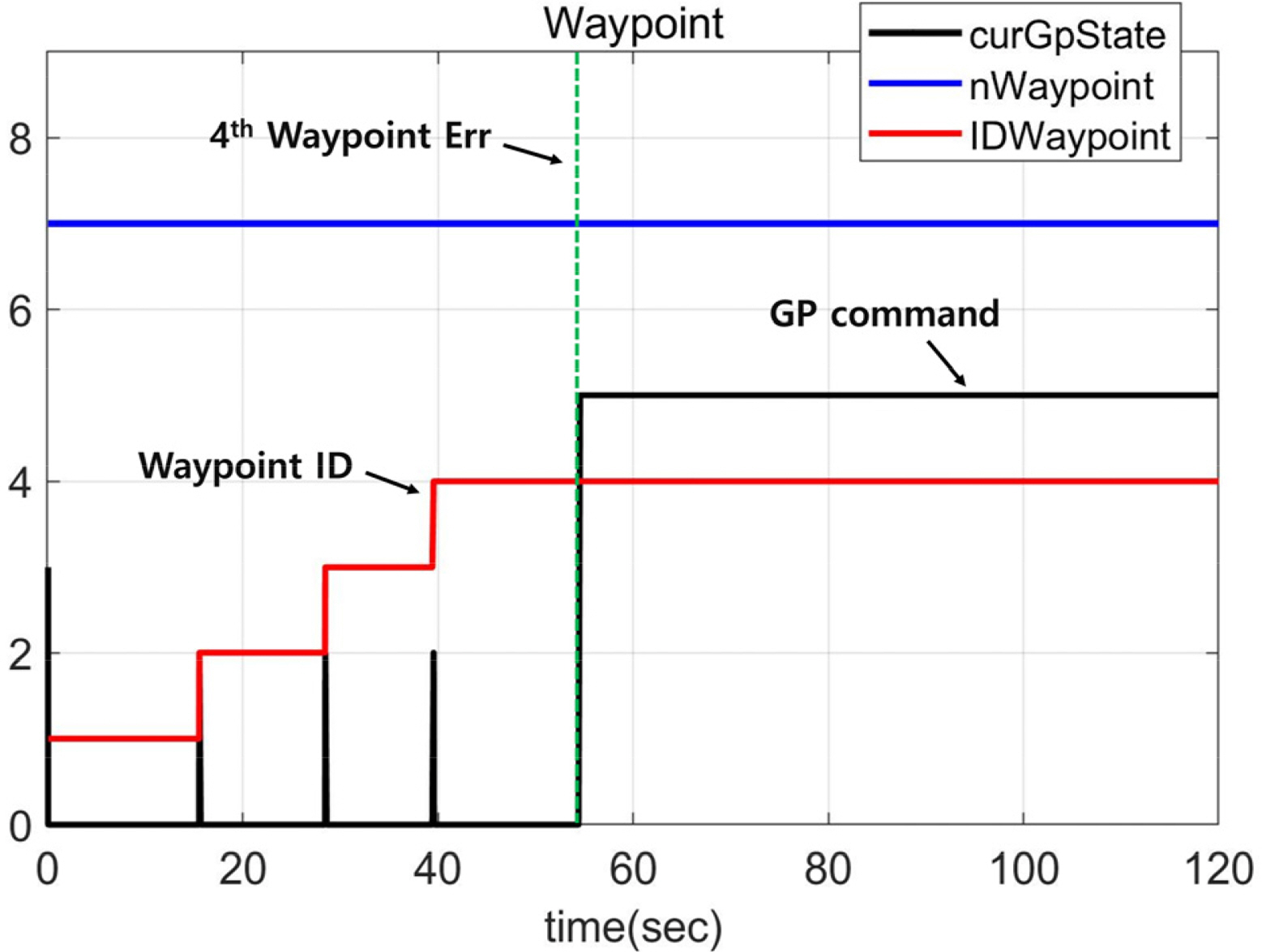
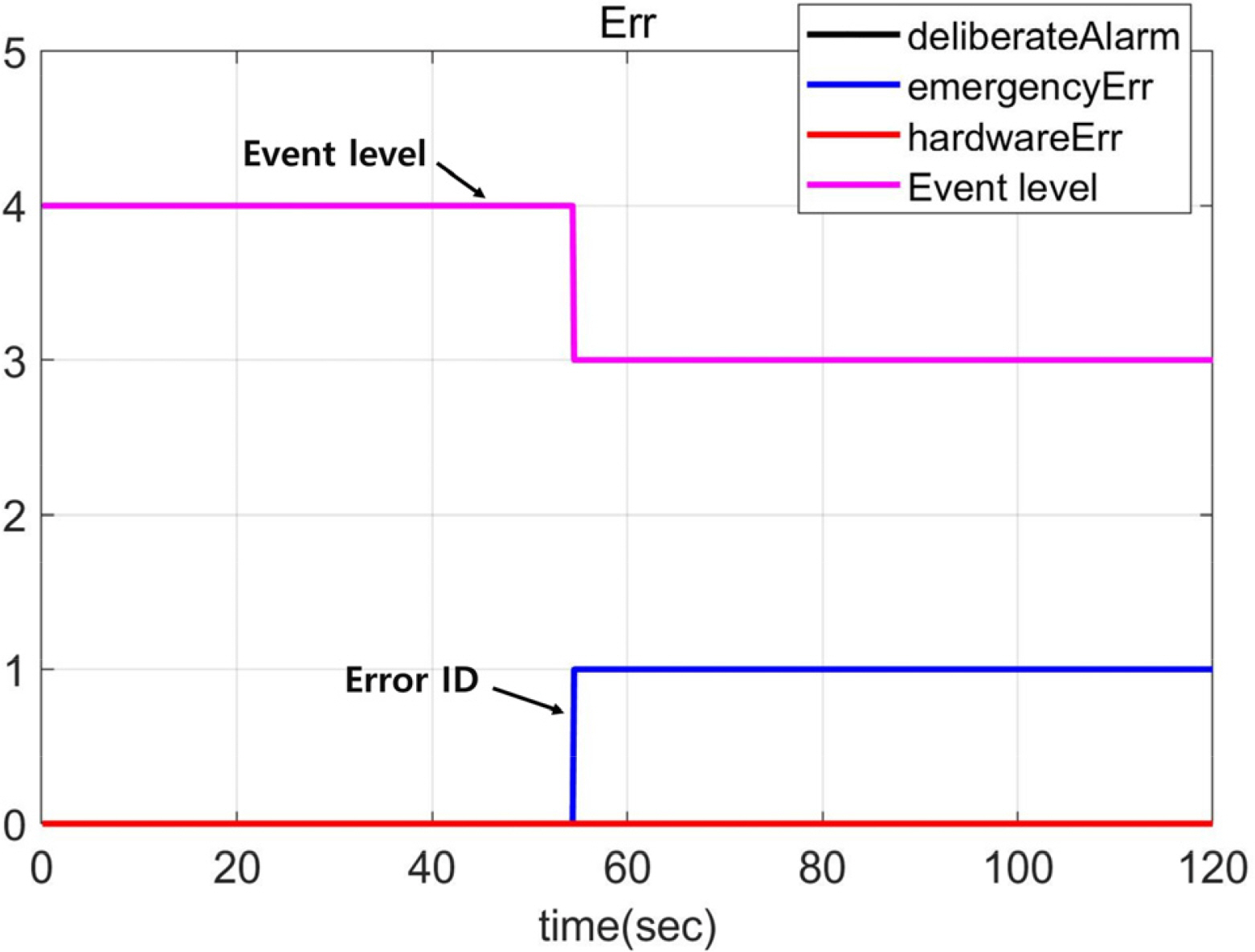
Fig. 11 shows the result of simulating the abnormal state in which the AUV does not pass a set waypoint. As shown in Fig. 12, because waypoint #4 is not reached, the waypoint ID is maintained at 4. The algorithm determines that the AUV has missed waypoint #4 and calls GP 5. As shown in Fig. 13, the errorID for an unreached waypoint (emergencyErr) is triggered, and Event 3 is called. The algorithm was partially modified later to allow the AUV to float to the surface if a waypoint was not reached to prevent the loss of the AUV in the subsequent underwater experiment.
As a result of testing the mission management algorithm on land, the adequate interconnection of the algorithm with the other algorithms was confirmed, with the FIA level, event level, and GP command accurately determined based on the situation.
4.2 Sea Test
After verifying the performance of interconnection with the internal software of the AUV and the basic operational performance on land, an experiment was conducted in the actual sea environment, as shown in Fig. 14, to verify the docking performance of the AUV. To prevent the loss of the AUV, the AUV was attached to fishing lines, followed by the experiment support ship.
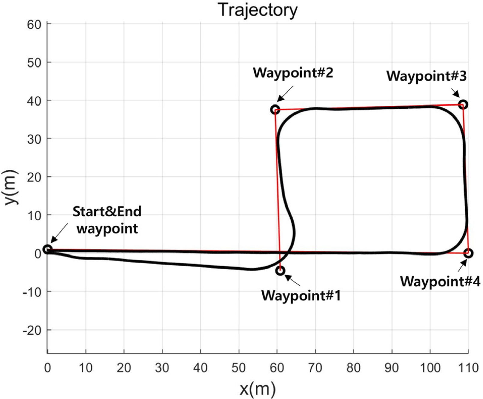
As shown in Fig. 15, five waypoints in the shape of a square, excluding the start point, were considered as the waypoints for the AUV. The AUV arrived at the final location without deviating or missing a waypoint. Eq. (1) was used to determine the arrival at each waypoint, and, which refers to the arrival radius at each waypoint, cir cleSize was separately defined. Waypoint#1 to waypoint#4 were set to 10 m to consider the operating conditions, such as the AUVŌĆÖs rotation radius and movement stability, and end waypoint was set to 0.2 m to consider the size of the docking cone as the final docking point.
Subsequent to the input of the preset initial value shown in Fig. 16 (a), the FIA level was observed to be properly managed according to the distance between the AUV and final waypoint (docking station), as shown in Fig. 16 (b). The AUV entered the 30 m radius in 185.6 s, with the FIA level was changed to FIA 2. When the AUV entered the 15 m radius at 195.6 s, the FIA level was changed to FIA 3. Fig. 17 shows the adequate management of the GP command as the AUV passed through the specified waypoints. The change of the waypoints and the normal operation were confirmed until 205.5 s, with the arrival at the last waypoint confirmed at 205.6 s. At 205.7 s, the mission complete GP command was called. Fig. 18 shows that the event level was properly managed during the docking mission. After setting the initial value, the normal state of the AUV was maintained.
As a result of testing the mission management algorithm in the actual sea environment, it was confirmed that the FIA level, event level, and GP command were accurately determined based on the situation. In the actual sea experiment, the abnormal state was not tested owing to safety issues of the AUV.
When the adequate operation of the mission management algorithm was confirmed, five differently shaped paths were each attempted twice with a total of 10 docking attempts (Fig. 19). As a result, docking was successful in all the attempts, achieving a success rate of 100%.
5. Conclusions
While AUVs must perform missions without external intervention given the constraints of the operating environment, USVs have been used in previous studies to allow operators to intervene under limited conditions. In addition, considering the nature of docking missions that require precise location estimation and maneuver, AUVs are equipped with multiple guidance and navigation sensors and state detection sensors, making the hardware and software structures of the AUVs complex, in contrast to those of conventional AUVs. The AI planner was not used in the mission management technique in this study because it would involve several constraints for the application in the AUV used in the experiment. In this study, a mission management technique was introduced to efficiently utilize and manage various sensors to perform docking missions without external intervention. The proposed technique defined the FIA level, event level, and GP command by reflecting the operating environment and docking scenarios of the AUV. The different sensors were effectively utilized, and the docking success rate was increased by defining the FIA level based on the characteristics of the AUV and mounted sensors. In addition, the event level was specified based on the hardware and mission status of the AUV to ensure stability in the mission performance of the AUV. Finally, it was possible to autonomously respond to various situations that could occur during docking by defining the behavior of the AUV with the GP command based on the situation. The adequate operation of the proposed algorithm was verified on land and in a real sea environment. In addition, by achieving a docking success rate of 100% (10 out of 10 attempts) in the sea environment, the problem of low docking success rates observed in previous studies was addressed, while the operability in an actual sea environment was demonstrated. However, given the safety issues of the AUV, certain situations were excluded and not verified experimentally. We plan to supplement the algorithm and verify the stability of the mission management algorithm under various conditions through additional experimental scenarios by February 2022.