1. Introduction
Recently, there has been increasing interest in unmanned underwater vehicles (UUVs) that can be used in marine accidents and extreme environments. This is because of the challenges involving the reliance on divers, including the risk of secondary accidents and short exploration times. However, UUVs can perform explorations for long periods of time without secondary accidents, such as human causalities. However, to enable the frequent use of UUVs, it is necessary to overcome the challenges associated with strong currents.
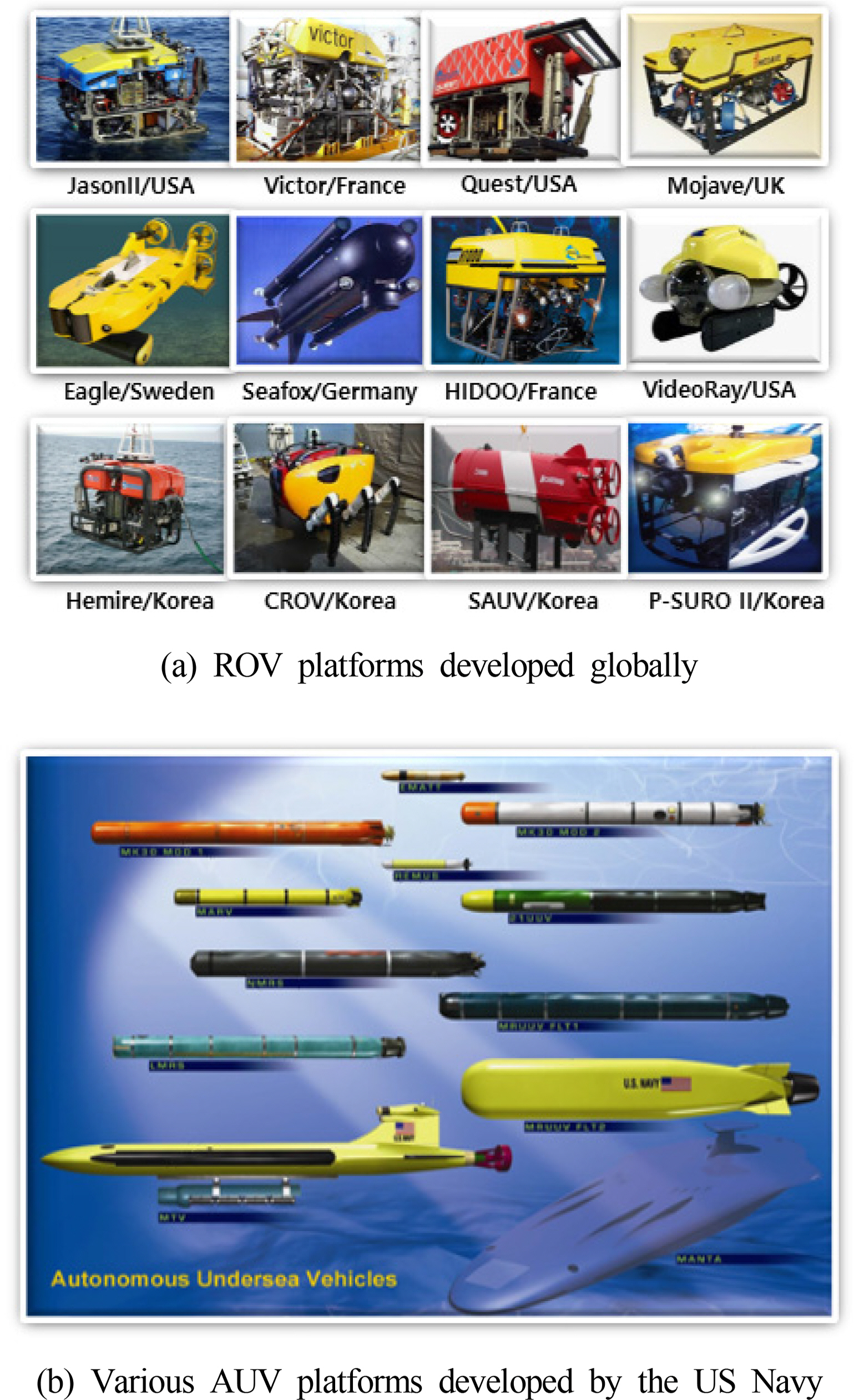
Existing UUVs can be broadly divided into two categories: remotely operated vehicles (ROVs) and autonomous unmanned vehicles (AUVs). Most ROVs have a box-shaped exterior, as shown in Fig. 1(a), which enables the exploration of specific areas in detail as well as the performance of underwater tasks using manipulators. Such forms are excellent in terms of control stability, but they have the disadvantage of being vulnerable to current owing to their high drag coefficient underwater. AUVs are mostly used for the rapid exploration of large areas. Therefore, they have the structural characteristic of a torpedo-shaped exterior, as shown in Fig. 1(b), and their three-dimensional (3D) movement in water is controlled using thrusters and rudders attached at the rear. Owing to the structural properties of such propulsion systems, they are quickly able to provide speed and stability in the forward direction, but their maneuverability is markedly poor, and they have difficulty operating normally in environments with irregular currents.
Early research was performed by the Korea Research Institute of Ships & Ocean Engineering on multi-legged biomimetic submarine robots called CR200 and CR6000 (Jun et al., 2013; Yoo et al., 2014). These research efforts involved the use of a new concept to overcome currents by landing on the sea floor and walking in current environments, which was based on structures that use six legs to perform swimming rather than the conventional propellor method. However, it was found that there remained a challenge of moving on the sea floor in environments with currents of 1.03 m/s or more owing to the large external structure of the robot itself. Pyo and Yu (2016) performed a study on a two-body AUV called MI (Mission: Impossible). In strong current environments, the AUV attaches to the sea floor, where the bottom part acts as an anchor and the top part uses a detachable structure to explore the current environment. For detailed explorations, there is still a difficulty with respect to having the top part overcome the current and approach the target object, but it is still considered to be an effective attempt. Unfortunately, only a conceptual design was produced, and there has been no further design, manufacturing, or research.
This paper discusses research on effective methods that are employed to overcome strong current through an optimized design of a UUV’s streamlined external structure and propulsion system. Technical research on these research items was performed with the support of the Ministry of Maritime Affairs and Fisheries’ Future Marine Industrial Technology Development Program, Korea (Li et al., 2019a).
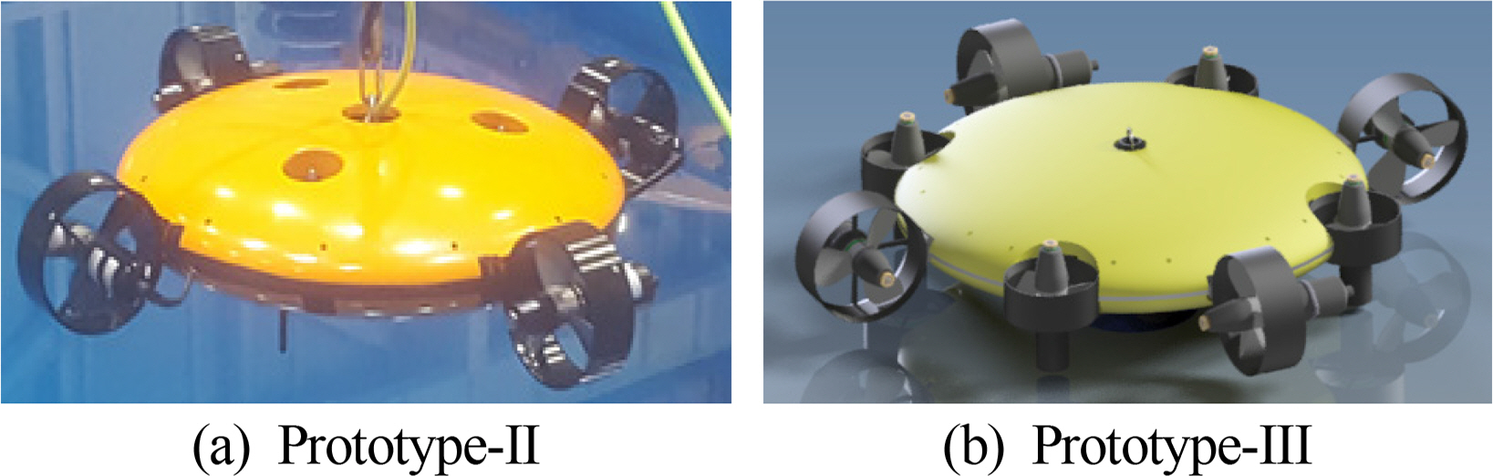
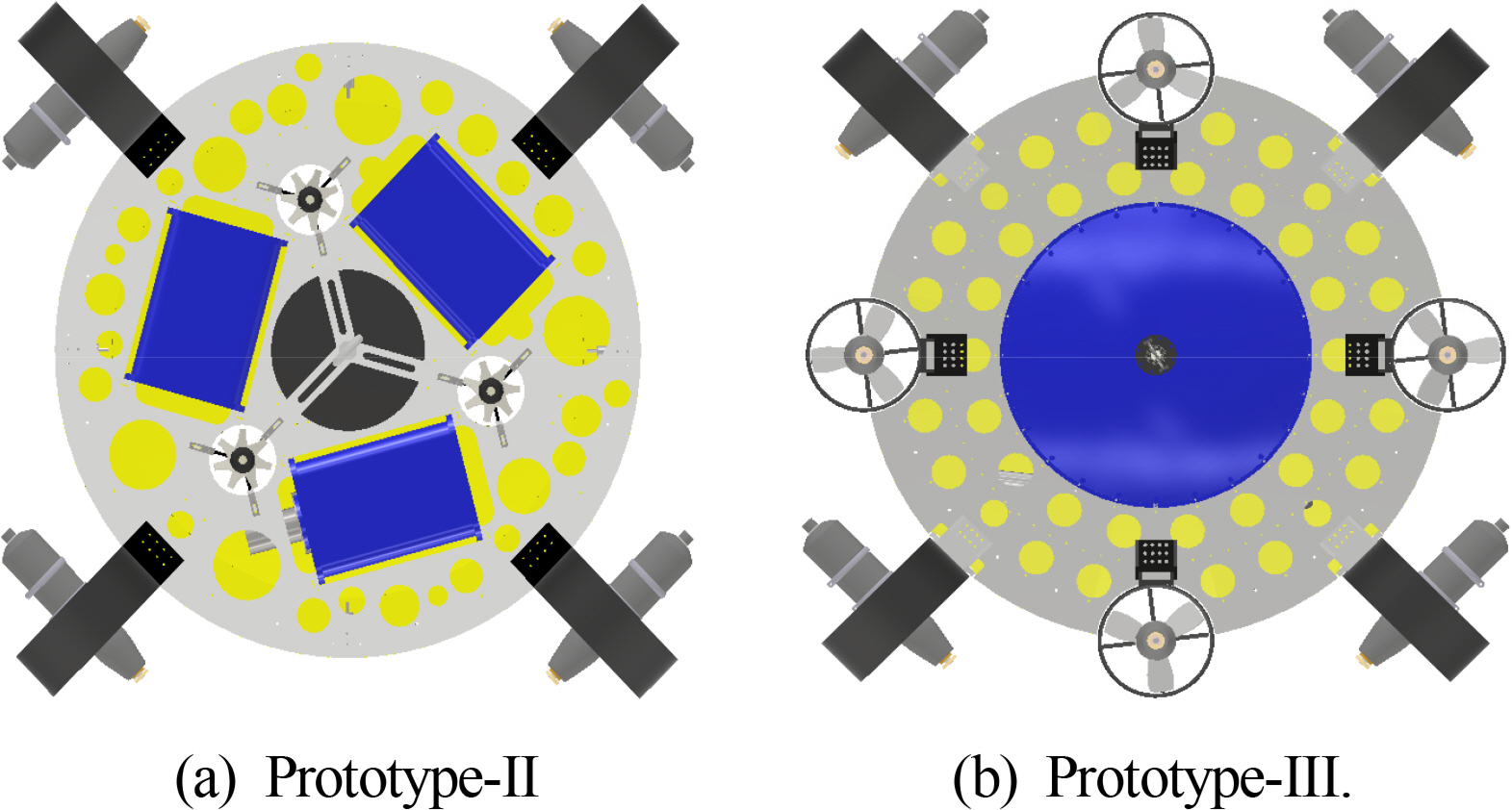
The UUV platform that was developed in the second year of this study is shown in Fig. 2(a). It was confirmed to have a maximum forward speed of 2.16 m/s underwater, and it can move forward even in a circulating water channel of 1.29 m/s (Li et al., 2019a). However, the three vertical propellers are attached close to the platform’s center point, and it was difficult to ensure control stability on the platform’s horizontal plane in strong current environments. This problem makes it difficult to operate in an environment with irregular currents, which is the main purpose of the platform. To overcome this problem in the UUV Prototype-III, the capacity of the vertical propellers was expanded, and the number of propellers was increased from three to four, and they were installed on the outer parts of the platform, as shown in Fig. 2(b). Because of these structural features, the platform’s drag coefficient underwater increased, and the maximum forward speed reached 1.85 m/s; however, experiments in a circulating water channel confirmed that it was possible for the platform to move while maintaining its depth and attitude in an environment with a maximum current of 0.77 m/s because stability in the horizontal plane was assured.. This paper mainly discusses research on Prototype-III of the UUV for overcoming strong current, which was researched and developed in the third year of this study.
2. System Overview
2.1 General Specifications
As shown in Fig. 2(b), the robot platform has a structure in which the pressure vessel, buoyant material, and propellors are attached to a single circular frame. The sensors for the navigation system include an acoustic Doppler current profiler (ADCP) in the lower part of the platform and an attitude heading reference system (AHRS) inside the pressure vessel. The propulsion system for swimming includes four vertical thrusters and four horizontal thrusters arranged symmetrically on the circular frame. A streamlined shape was chosen for the platform’s exterior to ensure forward speed through low drag, and it was designed as a circular shape in order to increase the platform’s capacity to respond to changing current. The integrated platform’s general specifications are shown in Table 1.
2.2 Mechanical System
The platform was designed for a working depth of 100 m. Considering the platform’s specific gravity and corrosion resistance, the frame and pressure vessel were designed with AL6061-T6; further, the design was optimized by performing thickness calculations (Moon et al., 2009) and structural analysis based on target values that consider the usage environment. Urethane foam was used as the buoyant material, and its mechanical stiffness was improved by coating the exterior thinly with glass fiber reinforced plastic (GFRP).
2.3 Surface Control Unit
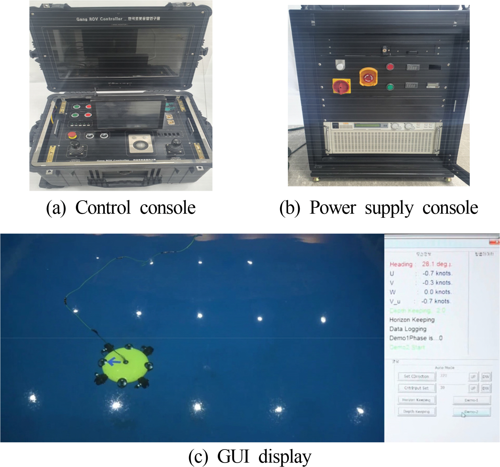
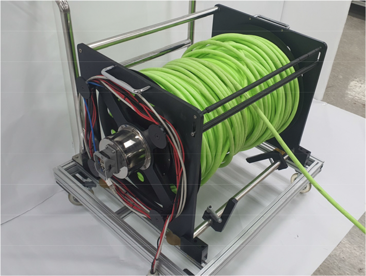
The robot’s operating system consists of a shipboard control system (Fig. 3) and a cable winch system (Fig. 4). The shipboard control system consists of a 330 VDC power supply unit, which is required for the thrusters, and a remote control system that is installed on a mobile console. All of the algorithms required for control of the robot are run from the remote control system, and the calculated control commands are sent to the platform in real time via the tether cable’s optical communications channel. Monitoring, control, and management of the platform are performed using the graphical user interface (GUI) screen of the shipboard control system.
The tether cable consists of an eight-line power wire and four communications channels. In addition to the slip rings, the wench system includes a communications converter for converting from optical communications to ethernet communications, as well as a video signal converter for converting from optical communications to video signals.
3. Vehicle Design and Its Hydrodynamic Modeling
3.1 Devices Arrangement and Mechanical Design
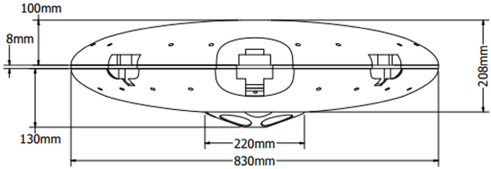
In the design of a platform for overcoming strong current, the aspect that is considered first is the minimization of the drag experienced by the robot underwater. To achieve this, it is necessary to consider the overall form and optimize the arrangement of equipment such as the thrusters and the ADCPs. Then, a miniaturized light-weight design should be developed for the frame and pressure vessel in the robot design stage.
First, in order to minimize the drag on the exterior, the Mring equation was used to calculate the basic exterior dimensions. After the initial values were calculated with this formula, essential equipment such as the thrusters and pressure vessel were arranged, and optimization was performed with a design-analysis-redesign approach. Considering the reduction in the platform’s overall size, the increase in usability, and the convenience of making modifications, the thrusters were externalized. To minimize its impact, an optimal design was created by performing the structural analysis of the ducts and the duct-frame connectors, and the additional drag was minimized through fluid analysis.
To resolve the problem of the unstable attitude control on the horizontal plane that occurred in Prototype-II, the number of vertical thrusters was increased from three to four, and their distance from the centrifuge was increased. Taking this into account, the three separate pressure vessels in Prototype-II were integrated into a single pressure vessel and located at the center of the platform in Prototype-III (Fig. 5).
Generally, when ultrasonic sensors such as Doppler velocity logs (DVLs) and ADCPs are used in UUVs, they are located on the bottom-most part of the platform to minimize the effect of sonic interference. Further, it is advantageous to locate them at the center bottom of the ADCP in order to improve static stability through a low center of gravity. However, in this case, owing to the properties of the disc-shaped platform, they overlap with the location of the pressure vessel and unavoidably increase the height of the platform, which can lead to an increase in the platform’s fluid resistance.
This problem was resolved by inserting the ADCP inside the pressure vessel, locating the ADCP sensor on the bottom of the pressure vessel, and placing the ADCP electronics in the center of the pressure vessel interior.
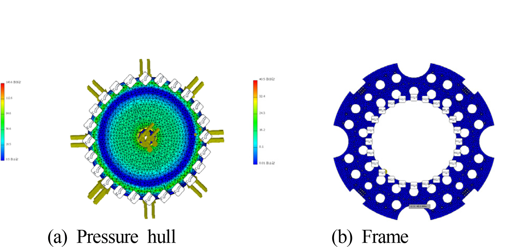
The thickness of the pressure vessel was calculated based on a thickness formula (Moon et al., 2009). However, to ensure reliability, additional verification was performed on the top cover by performing a structural analysis because the top cover is a part that directly receives a load. As shown in Fig. 6(a), the structural analysis results confirm that the top has a safety factor of around 1.67 compared to the yield strength of the material, as listed in Table 2. This is a higher figure than the factor of 1.2 to 1.5 that is generally stipulated in ship classification regulations, indicating that it has excellent stability. The pressure vessel that was manufactured according to this design was pressure-tested at the Korea Research Institute of Ships & Ocean Engineering by applying a pressure of 1 MPa for 30 min in a pressure chamber. As a result, it received accreditation from the Korea Laboratory Accreditation Scheme (KOLAS), confirming that there was no deformation or leakage.
The four vertical thrusters were arranged symmetrically in relation to the designed pressure vessel. To reduce the drag that occurs owing to the vertical thrusters, the neutral duct exterior was miniaturized in keeping with 100-m specifications, and the thrusters were located at the ends of the platform interior, considering interference with the pressure vessel. By doing so, control stability on the horizontal plane was increased.
For the horizontal thrusters, this study selected a model in which the forward thrust matches the reverse thrust, and the thrusters were arranged symmetrically on the circular frame. This ensures that if the maximum thrust of one thruster is Fmax, the maximum thrust on the horizontal plane is
2 2 F max
In addition, the buoyant material was placed on the top of the frame, and the exterior systems and pressure sensors were attached to the bottom. This was done to improve the platform’s attitude recovery capacity by increasing the relative height of the center of buoyancy and the center of gravity.
In order to confirm the structural stability of the frame at the points at which equipment such as the pressure vessel and thrusters was attached, a similar structural analysis was performed. The analysis targeted the launch and recovery environment, which applies the greatest dynamic load among the various environments in which the UUV is used. The boundary conditions for the frame parts that are connected to the lifting eye during the analysis were set, and the analysis was performed. As shown in Table 2, the results confirmed that the design has a safety factor of 5.8, which is somewhat higher than the safety factor of four, and takes into account the dynamic load generally caused by waves or wind during launch and recovery.
3.2 Vehicle Modeling
As mentioned previously, this study designed the system using four vertical thrusters to maintain stability in the platform’s horizontal plane, i.e., to keep the platform’s roll and pitch angles at 0 degrees at all times. In other words, the four vertical thrusters were designed as dedicated controllers in order to maintain the robot’s horizontal plane. Based on this premise, this study estimated the hydrodynamic coefficients of the robot platform by limiting them to the horizontal plane, and they were then used in the simulations.
3.2.1 Vehicle’s horizontal kinematics and dynamics
In general, the kinematics and dynamics of a UUV can be expressed as follows (Fossen, 2002; Li et al., 2019b).
Here, η =[x,y,ψ]T is the vector of the robot’s horizontal plane position and attitude in the navigation coordinate system, ν =[u,v,r]T is the vector of linear and rotational speed in the horizontal plane in the robot body coordinate system, and
C b n
In this study, the robot platform has a top/bottom, left/right symmetrical structure. Adjustments were made to place the platform’s center of gravity at (x0,y0 )=(0,0) by performing repeated ballast operations on the assembled platform underwater. Based on the results, the platform’s rigid body inertial matrix MRB and Coriolis and centrifugal force matrix CRB in Eq. (1) can be expressed as below.
Here, m is the rigid body mass, and IZZ is the rotation moment about the center axis on the horizontal plane, as shown in Table 3.
Fig. A1 and Table A1 in the appendix show the dimensions of the UUV frame used to calculate IZZ which is the rotational moment in the horizontal plane.
Hence, ΣFext in Eq. (1) can be expressed as follows.
Here, Fdrag is the hydrodynamic damping; Fadded mass is the added mass; and Fcontrol is the control input.
3.2.2 Hydrodynamic damping Fdrag
The robot platform discussed in this study has a structure that is symmetrical in the X, Y, and Z axes in three-dimensions. Therefore, the moment component caused by linear motion and the force component caused by rotational motion are both ignored in this study. In addition, the UUV platform model was simplified, as was done in Prestero (2001), and the following two additional assumptions were made to avoid overly complicated mathematical calculations.
As a result, the Fdrag component can be simplified as follows.
The corresponding hydrodynamic coefficients were calculated using the following empirical formulas (Newman, 1977; Prestero, 2001).
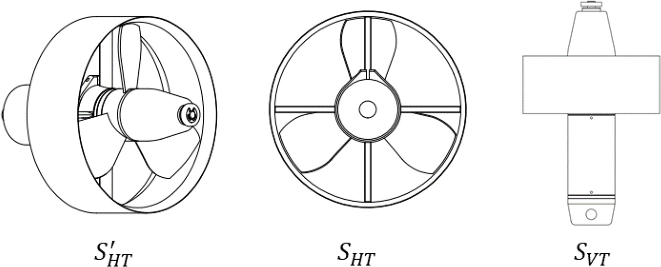
Here, ρ is the liquid density, and cd, cdHT, and cdVT are drag coefficients that correspond to the platform’s ellipsoid, horizontal thrusters, and vertical thrusters. and are the major axis and minor axis in the ellipsoid’s horizontal plane. sHT, sVT, and s′HT are the cross section areas that correspond to each thruster (Figs. A1,–A3). Table A2 in the appendix shows the cross sections for each thruster.
The calculated damping coefficients are shown in Table 4.
3.2.3. Added mass Fadded mass
To calculate the additional mass coefficient, this study only considered the diagonal components in the additional mass matrix via the platform’s symmetrical structure. The corresponding coefficients were estimated as follows using an empirical graph presented in the literature (Newman, 1977).
The added mass coefficients are shown in Table 5.
Based on the results, the model of motion and dynamics on the robot’s horizontal plane can be set up as follows.
Here, Fcontrol = [Fu, Fv, Fr]T are the control inputs.
4. TVC Algorithm
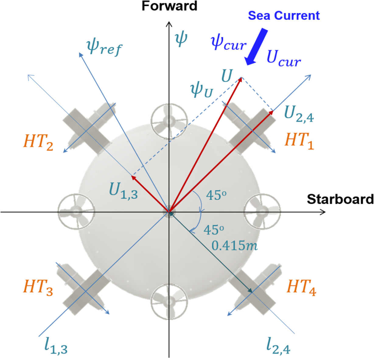
When the robot performs a given task underwater, the ADCP attached to the bottom of the robot platform can measure the flow speed Ucur and direction ψcur of the current in real time as it flows in any direction. The main objective of the control algorithm in this study is to use the four horizontal thrusters to overcome this current while maintaining the robot’s given horizontal plane motion (xref (t), yref (t), ψref (t)) (Fig. 7).
4.1 Model-based Controller Design
Assuming that the robot’s model, i.e., the hydrodynamic coefficients, is accurately known, it is possible to design the controller using a general backstepping technique (Krstic et al., 1995; Li, 2016), as shown below.
Step 1. As mentioned before, the control objective here is to maintain the given motion (xref (t), yref (t), ψref (t)). In addition, in this stage, the following Lyapunov function candidate is considered.
Here, xe = xref − x, ye = yref − y, 및 ψe = ψref − ψ; γψ >0 is a design variable.
If (Ux, Uy, r) in Eq. (12) are seen as virtual control inputs, and (αUx,αUy,αr ) is the corresponding stabilizing function (Kristic et al., 1995), Eq. (12) can be expanded as follows.
Here, eUx = αUx −Ux, eUy = αUy − Uy, and er = αr − r
The following control rules were selected in Step 1 based on Eq. (14).
Here, kx, ky, kψ >0 is a design variable.
Step 2. In this step, a Lyapunov function candidate is selected, as shown below.
Here, eu = αu − u, ev = αv − v, and
[ α u α v ] = P b n ′ [ α U x α U y ] [ e u e v ] = P b n ′ [ e U x e U y ]
As a result, the final control input [Fu,Fv,Fr ]T can be designed as follows.
Lemma 1. If the control rules are designed as in Eqs. (15) and (19) based on the model of the UUV’s motion and dynamics given in Eqs. (9) and (10), it can be guaranteed that the robot maintains a given motion (xref (t), yref (t), ψref (t)) in a stable manner.
Here,
λ = min { k x , k y , γ ψ - 1 k ψ , k u , k v , γ r - 1 k r }
Hence,V2 can be known to converge at 0 exponentially.
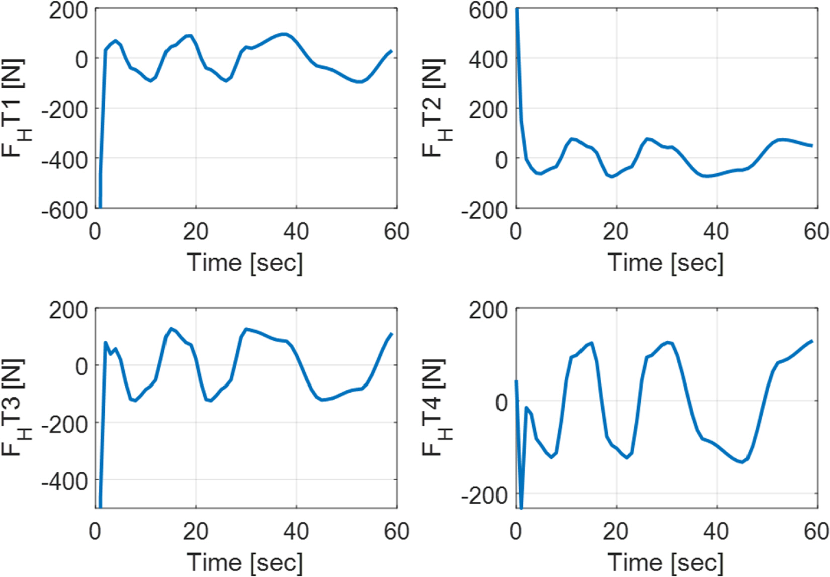
Remark 1. For the control input calculated in Eq. (19), the thrust corresponding to each thruster is calculated as follows based on the thruster arrangement shown in Fig. 7.
Here,
B = [ 2 2 2 2 2 2 2 2 - 2 2 2 2 - 2 2 2 2 - 0.415 0.415 0.415 - 0.415 ]
Finally, the control input for each thruster is calculated using the chart of thruster control input1) vs. thrust provided by the thruster manufacturer based on the thrust of each thruster calculated in Eq. (21).
Remark 2. The controller design presented in this section is based on the premise that the model of the UUV’s motion and dynamics is accurate. However, in the case of an actual system that has strong nonlinear dynamic properties, such as a UUV, it is quite difficult to accurately derive hydrodynamic coefficients in advance. To handle the uncertainty in systems that include such a modeling error, a robust and adaptive controller design is needed (Li, 2016 and references therein).
4.2 Experimental Study-Based TVC Method
Generally, UUVs have strong nonlinear dynamic properties owing to the environments in which they operate and their own kinematic properties. Furthermore, it is difficult to accurately simulate robot models in actual applications. Therefore, when applying the control techniques that were proposed in the previous section, precise motion control cannot be guaranteed.
To overcome these problems, this study performed field experiments to derive the formula for the relationship between the thruster control input and the robot’s forward speed. Based on this formula, this study attempted to find a simple control method for handling current flowing in any direction.
In this study, the forward and backward thrust models for each horizontal thruster are the same, and the four thrusters are all arranged with left/right and front/back symmetry, as shown in Fig. 7. Furthermore, this study adopted an approach that groups HT1 and HT3 into one set and HT2 and HT4 into a separate set, and it applies the same control input to the two thrusters of each set. In this case, the thrust vector of the thruster set located in the l1,3 line is always placed at l2,4; conversely, the thrust vector of the thruster set in the line is always located at l1,3.
Based on this concept, the formula for the relationship between the speed and control input Cinput = vel2vol(U)2) was found by applying different control inputs to the HT1, HT3 set (it is possible to apply the same relational formula to the HT2, HT4 set) in a water tank environment and measuring the robot’s corresponding speed (Li et al. 2019a). Based on this empirical relational formula, the following control rule is proposed.
Lemma 2. For a given arbitrary current (Ucur, ψcur ), the current can be overcome if the following control rules are designed.
Proof. Below is the speed vector U, which is composed of U1,3 and U2,4, which were calculated by Eq. (22) based on Fig. 7.
As a result, when the control input for a given current is designed, as shown in Eq. (22), the UUV is able to maintain the existing attitude.
In order to control the attitude on the robot’s horizontal plane while overcoming a given current, the following simple proportional derivative (PD) technique was used.
Here, δC =KP (ψref − ψ)+KD (ψ̇ref − r), and KP and KD are design variables.
Remark 3. The core of the TVC algorithm proposed in this section involves finding the formula for the relationship between the control input and the speed Cinput = vel2vol(U). In this study, the robot platform has both front/back and left/right symmetry, and it is possible to use the simple algorithm above when employing a method that divides the four horizontal thrusters into two sets, and applies the same control input to the two thrusters of each set. However, in the case of normal UUVs, it is very difficult to find formulas for the relationships between the control inputs for various situations and the corresponding speeds, and the use of the above control method will certainly be limited.
4.3 Simulation Study
A simulation was performed in Matlab using the robot’s dynamic properties, which are expressed in Eq. (10), as well as the coefficients in Tables 3,–5.
4.3.1 Maximum forward speed test
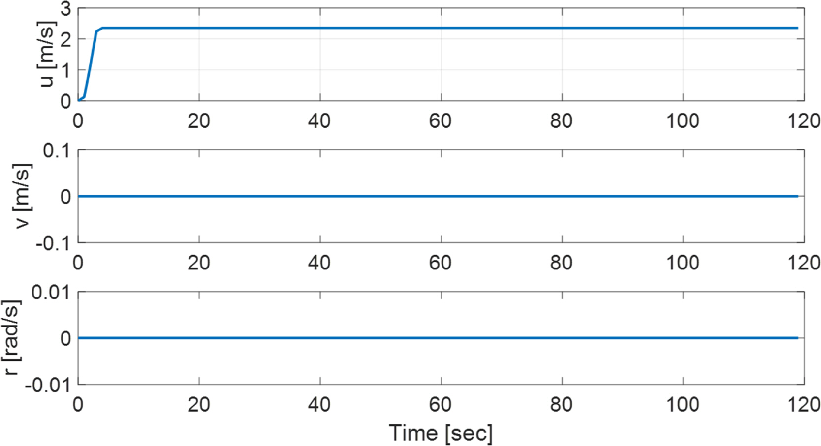
First, a 4.5-V control input (in the water tank experiments, a maximum control input of ±4.5 V was proposed to protect the thrusters) was applied to all four thrusters to estimate the maximum forward speed.
As seen in Fig. 8, the maximum forward speed is around 2.36 m/s. This is the result of using the simplified model, and it ignores the effects of using the tether cable, etc. as in the water tank experiments. In the actual water tank experiments, a maximum forward speed of 1.85 m/s was obtained.
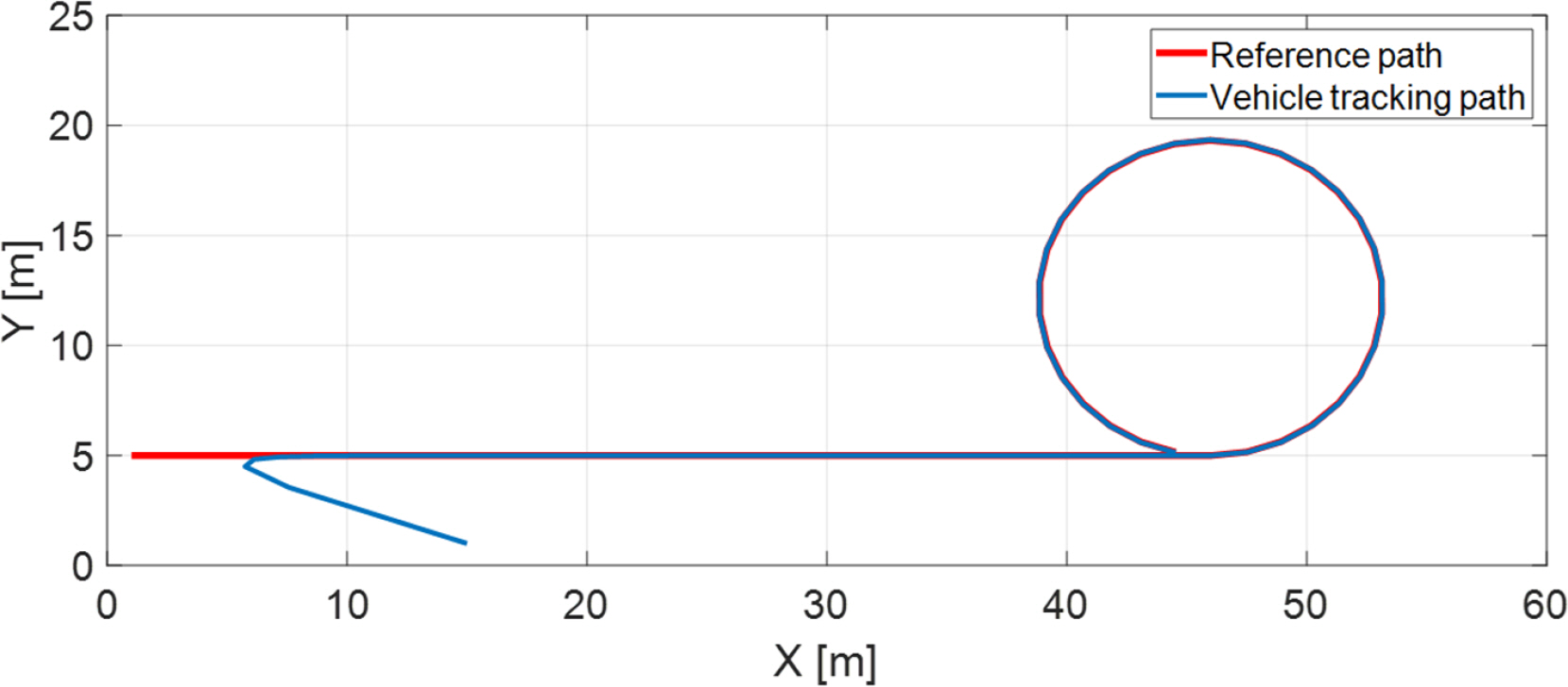
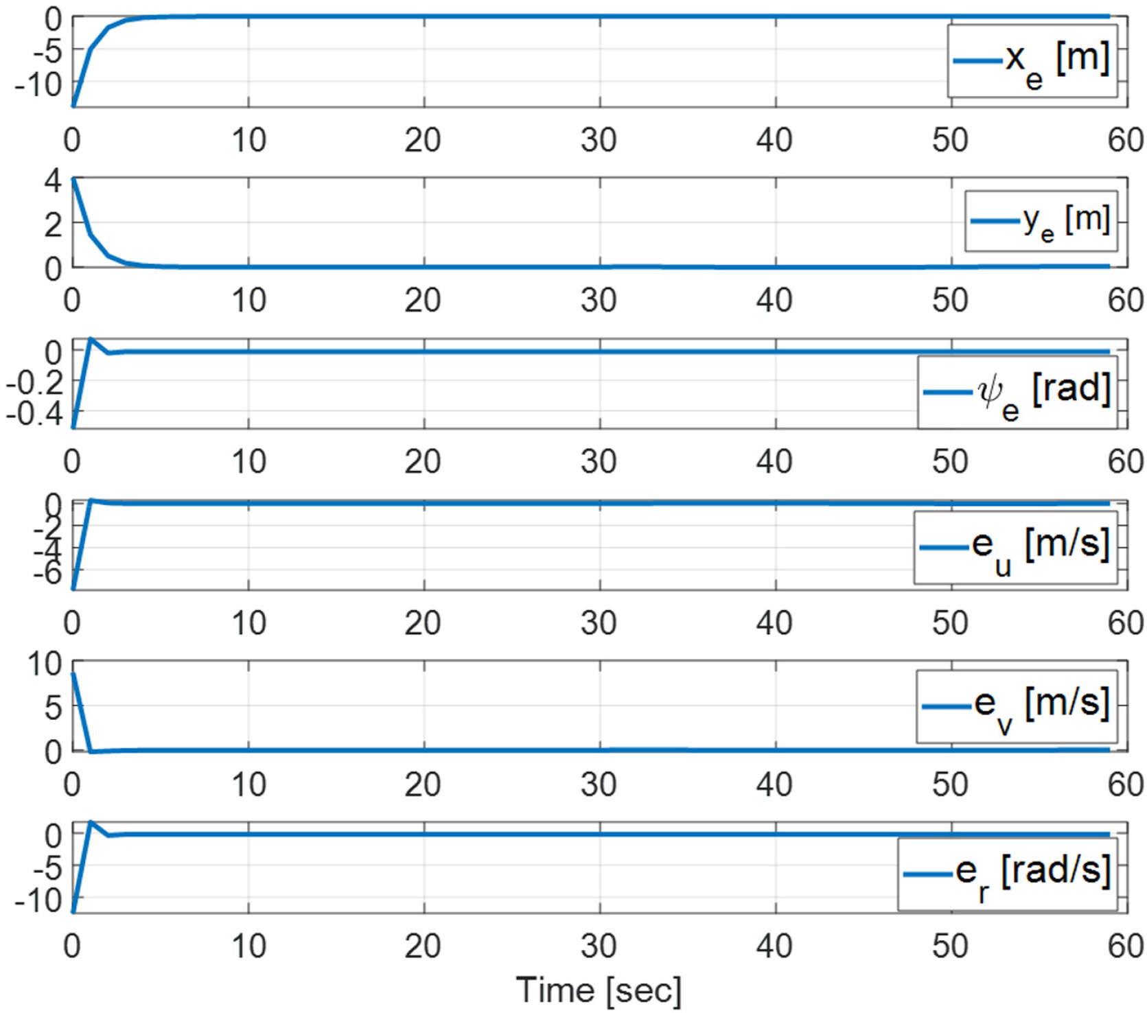
4.3.2 Path tracking with rotating motion
Owing to the structural properties of the robot platform, it is of interest to examine whether the platform can rotate at the same time that the robot’s center point traces a given path. To this end, the following simulation was performed. [ẋref, ẏref, ψ̇ref ]=[1.5cosθ(t), 1.5sinθ(t),2π/15], and here xref (0)= 1 m, yref (0)= 5 m, ψref (0)= 0, if t <0, θ(t)= 0; else θ(t)= 12°/s. The robot’s initial conditions are x(0)= 15 m, y(0)= 1 m, ψ(0)= 30°, u(0)= v(0)= r(0)= 0. For the control algorithm in the simulation, the technique introduced in section 4.1 was used, and the specific design variables are as follows.
5. Water Tank Experimental Studies
To verify the performance of the developed robot platform, i.e., its stability in the horizontal plane and its forward speed and performance in the horizontal plane, and to verify the ultimate performance of the proposed control algorithm, various experiments were performed at the Korea Institute of Ocean Science and Technology’s Underwater Robot Test Center (Kim et al., 2017). The water tank tests verified the robot’s performance at overcoming current using the TVC algorithm, which was mainly introduced in section 4.2. The water tank tests were broadly divided between an engineering basin and a circulating water channel, as shown in Fig. 12.
5.1 Basin Tests
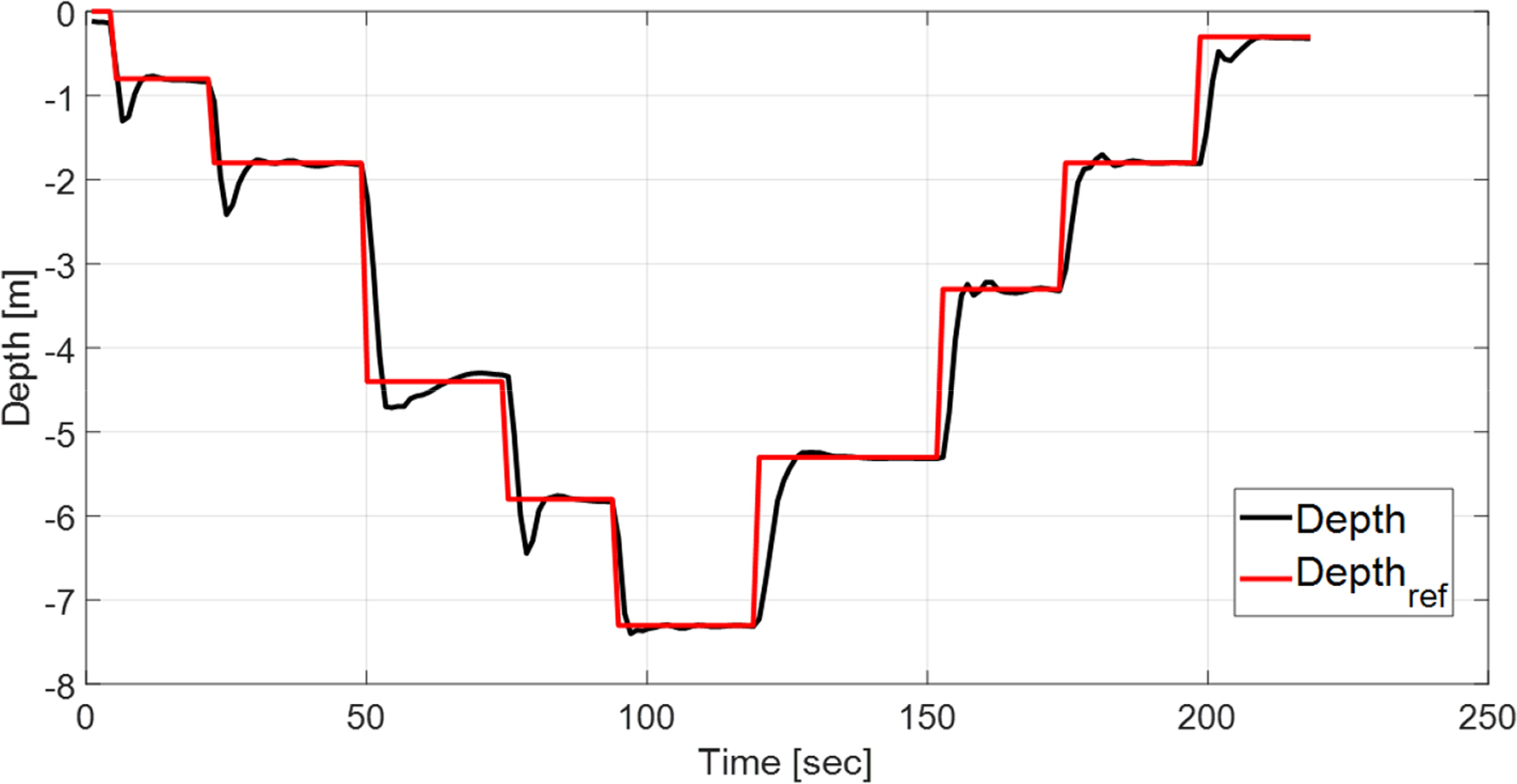
5.1.1 Depth and roll, pitch motion control
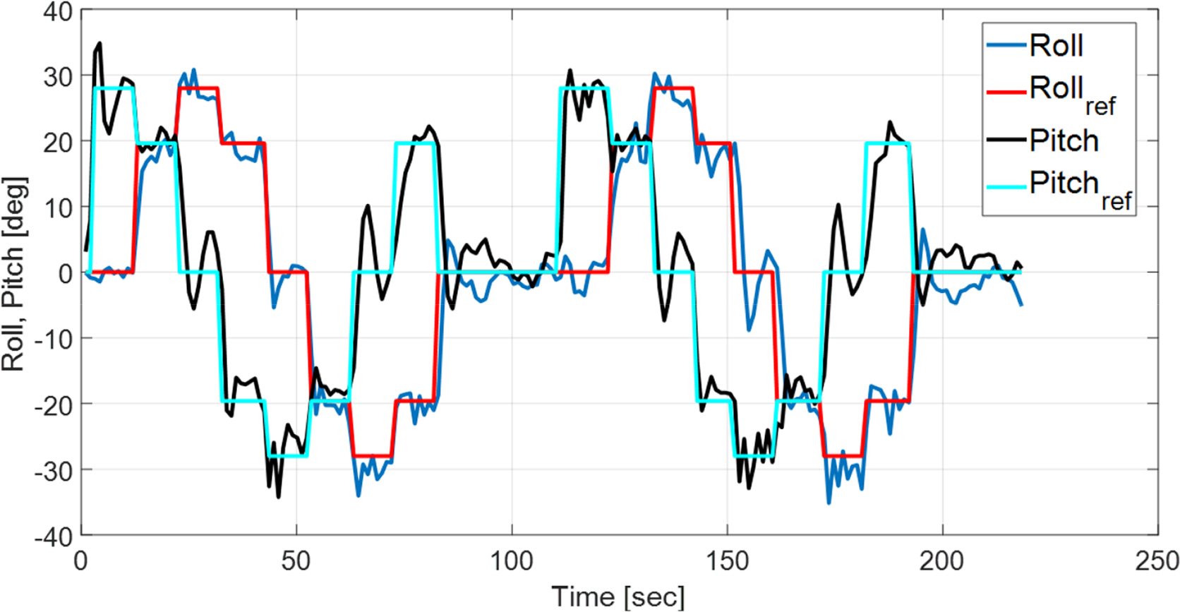
First, in order to verify the platform’s stability and general control performance, its depth, roll, and pitch control performance were examined.
As seen in Figs. 13–14, it was found that the platform is capable of rapid stable control according to the given depth, roll, and pitch control commands. Fig. 14 focuses on the control response speed to step-shaped reference values for the roll and pitch angles, and it appears that the platform’s tracking performance is somewhat poor because it does not have an adequate response time. However, in separate independent roll and pitch angle control experiments, it was found that the values converged in a stable manner within approximately 3° after around 10 s had elapsed.
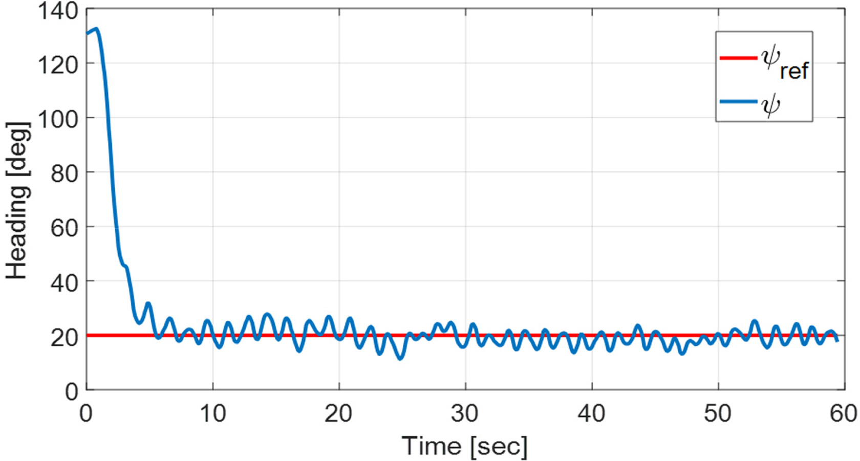
5.1.2 Heading keeping while encountering variant current
The following experiment was performed to examine the UUV’s attitude angle keeping (heading-keeping) in scenarios where the current direction changed over time. The given attitude angle was ψref = 20°, and a time-varying current was simulated as follows: Ucur = 0.5 m/s, if 0≤t <15 or t≥45, ψ̇cur (t)= 12°/s; else ψ̇cur (t)= −12°/s; else, ψcur (0)= 120°.
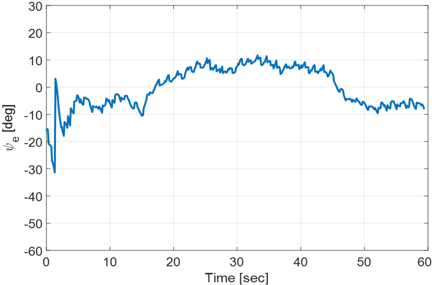
The experiment results are shown in Figs. 15–16. Fig. 15 shows the heading keeping error, and Fig. 16 shows the current direction tracking error ψe =− ψcur −[ψ + atan2(v,u)]. Here, ψU = ψ + atan2(v,u)is the robot’s forward direction (Fig. 7). In Fig. 16, it can be seen that ψe has an error of around 10°. This is believed to be due to the accuracy of the vel2vol(⋅)function mentioned in section 4.2, as well as the attitude angle error of the MEMS-based AHRS and the effect of drift.
5.2 Circulating Water Channel Tests
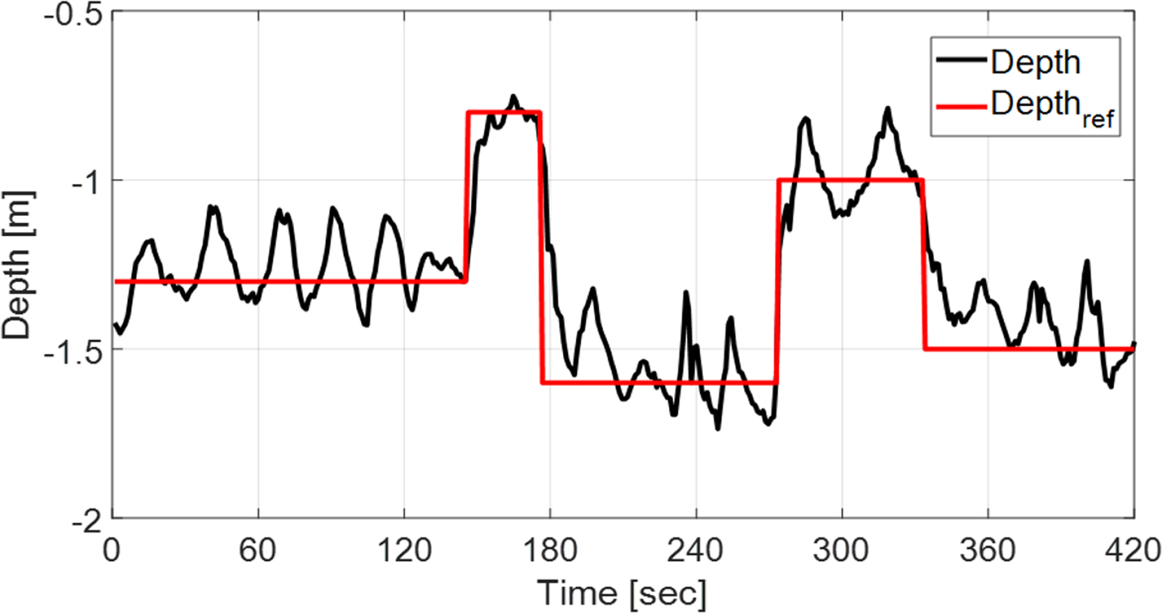
To verify the stability and control performance of the platform in an actual current environment, various control experiments were performed on the robot in a circulating water channel with a flow speed of around 0.62 m/s (refer to Fig. 12(b)).
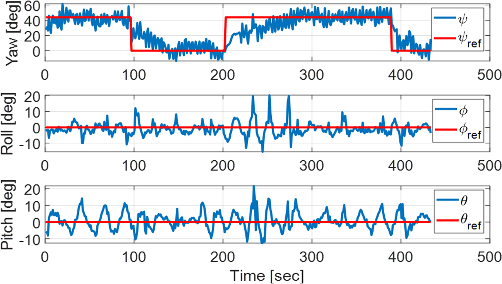
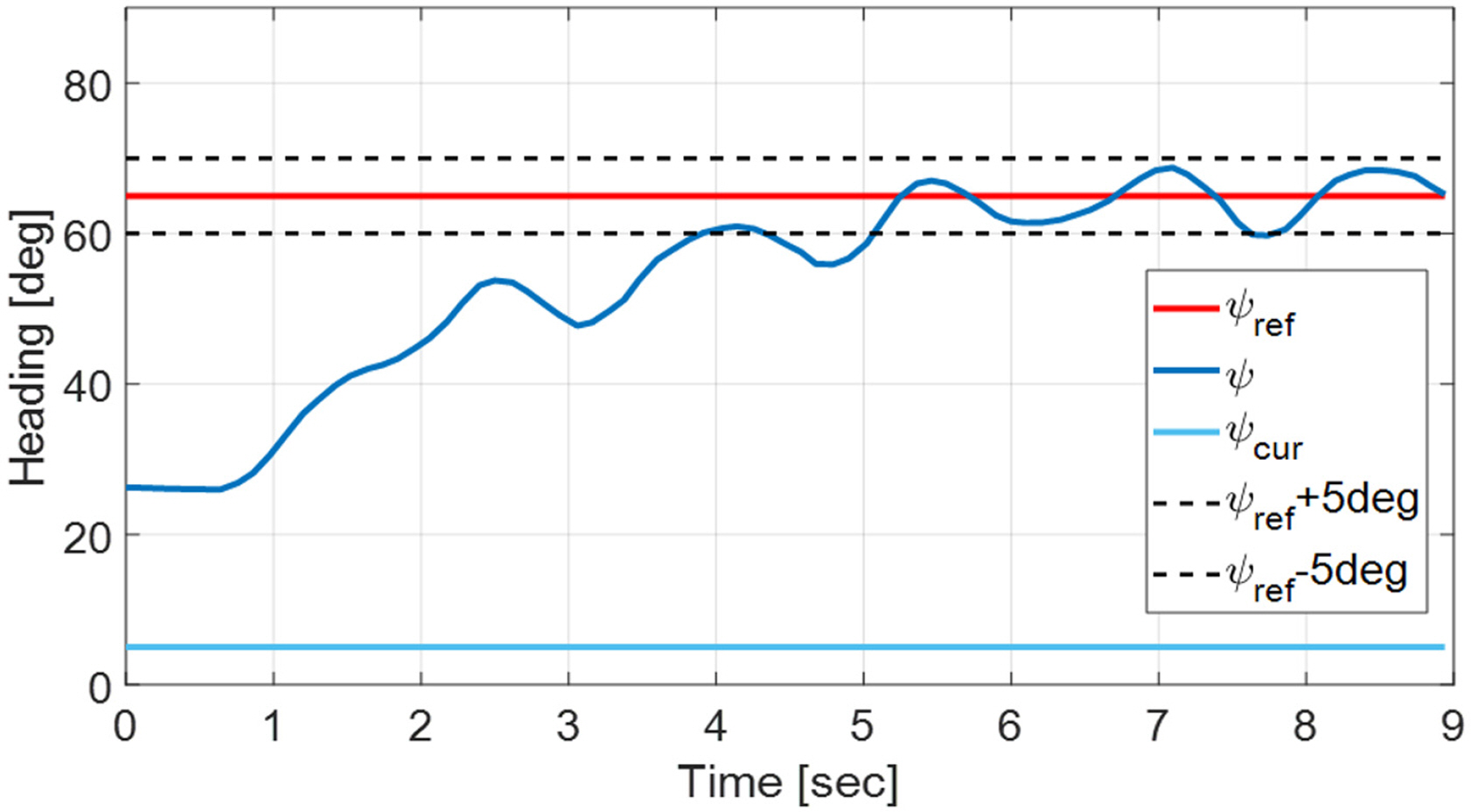
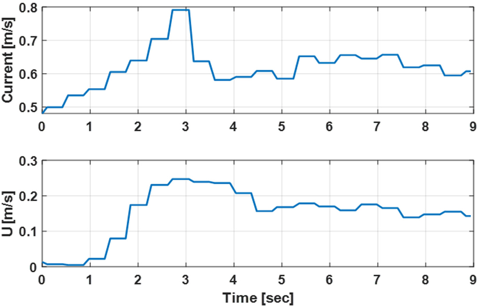
First, as in the basin tests, the platform’s depth and attitude control performance were examined. As seen in Figs. 17–18, the depth and attitude angles were tracked well overall, but the results had more fluctuations than those of the basin tests. Next, tests were performed on attitude control for a ψref that deviated from the current direction in the current environment, as well as the forward motion in the corresponding direction. As shown in Fig. 19, the robot converged to within ±5° of the given value of ψref . The current speed and the robot’s forward speed relative to the water tank floor that was measured at this time are shown in Fig. 20. It can be seen that the robot made forward progress as it overcame the current, and this was also confirmed visually.
6. Conclusion
This paper discussed the design of an unmanned underwater vehicle (UUV) platform that overcomes strong currents, as well as a corresponding effective control method. To minimize drag underwater, the UUV’s exterior was designed with a streamlined circular shape, and the size of the UUV was minimized through the optimal arrangement of the equipment and by designing and analyzing the mechanical systems in advance. A platform profile and empirical equations for the designed platform were used to create a simplified dynamics model and corresponding hydrodynamic coefficients, and these were used in a simulation study. This paper proposed an efficient and simple TVC algorithm by performing field experiments; after finding the formulas for the relationship between the platform’s control input and forward speed based on a structure in which the four horizontal thrusters on the disc-shaped robot platform all had front/back and left/right symmetry, the same forward/backward propulsion model was used. The ultimate performance of the developed platform and control algorithm was verified in a water tank and circulating water channel environments.
Because stable control is needed to operate in irregular current environments, the control difficulties that were found in Prototype-II were resolved by varying the performance, number, and location of the vertical thrusters. In doing so, the overall drag was increased and the maximum forward speed was reduced from 2.16 m/s to 1.85 m/s, but control stability in the horizontal plane was significantly improved. Hence, more stable attitude control was possible in the water tank experiments, especially in the circulating water channel experiments.
One limitation of this study was that the thrusters used were all off-the-shelf products, which had limitations concerning their weight and exterior shapes and hence could not maximize the vehicle’s speedIt is believed that if a propulsion system that is specialized for disc-shaped platforms is used, it will be possible to create a more effective technology for overcoming strong current.